Difference between revisions of "910.4 ITS Architecture"
m |
m (Per TS, replaced archaic “Motorist Assist” with "Emergency Response") |
||
| Line 130: | Line 130: | ||
Roadside Subsystems. Intelligent infrastructure distributed along the transportation network which perform surveillance, information provision and plan execution control functions and whose operation is governed by center subsystems. Direct interface to vehicle subsystems exist.<sup>2</sup> An example of a roadside subsystem could be a variable message sign on the interstate. | Roadside Subsystems. Intelligent infrastructure distributed along the transportation network which perform surveillance, information provision and plan execution control functions and whose operation is governed by center subsystems. Direct interface to vehicle subsystems exist.<sup>2</sup> An example of a roadside subsystem could be a variable message sign on the interstate. | ||
| − | Vehicle Subsystems cover ITS related elements on vehicle platforms. Vehicle subsystems include general driver information and safety systems applicable to all vehicle types. Four fleet vehicle subsystems (Transit, Emergency, Commercial Vehicles and the newly added Maintenance and Construction) add ITS capabilities unique to these special vehicle types.<sup>3</sup> Examples of vehicle subsystems include automatic vehicle location systems on transit vehicles or the | + | Vehicle Subsystems cover ITS related elements on vehicle platforms. Vehicle subsystems include general driver information and safety systems applicable to all vehicle types. Four fleet vehicle subsystems (Transit, Emergency, Commercial Vehicles and the newly added Maintenance and Construction) add ITS capabilities unique to these special vehicle types.<sup>3</sup> Examples of vehicle subsystems include automatic vehicle location systems on transit vehicles or the Emergency Response vehicles. |
Traveler Subsystems are equipment used by travelers to access ITS services pre-trip and en route. This includes elements that are owned and operated by the traveler as well as elements that are owned by transportation and information providers.<sup>4</sup> An example of a traveler subsystem could be an information kiosk at an [[:Category:122 Aviation|airport]]. | Traveler Subsystems are equipment used by travelers to access ITS services pre-trip and en route. This includes elements that are owned and operated by the traveler as well as elements that are owned by transportation and information providers.<sup>4</sup> An example of a traveler subsystem could be an information kiosk at an [[:Category:122 Aviation|airport]]. | ||
| Line 173: | Line 173: | ||
=====910.4.1.4.1.7 Market Packages ===== | =====910.4.1.4.1.7 Market Packages ===== | ||
| − | A market package provides an accessible, service-oriented perspective to the National ITS Architecture. They are tailored to fit, separately or in combination, real world transportation problems and needs. Examples of market packages include: network surveillance, emergency response, and maintenance and construction vehicle tracking. Market packages are a collection of one or more groupings of implementable processes. These processes must work together to deliver a given transportation service and the architecture flows that connect them and other important external systems. In other words, they identify the pieces of the physical architecture that are required to implement a particular transportation service. There are currently 75 Market Packages included in the most recent version of the National ITS Architecture (Version 4.0) that was planned for mass public release in April 2002. The most significant impact to Missouri is the additional 10 market packages oriented to support Rural ITS services. Since Kansas City and St. Louis have existing | + | A market package provides an accessible, service-oriented perspective to the National ITS Architecture. They are tailored to fit, separately or in combination, real world transportation problems and needs. Examples of market packages include: network surveillance, emergency response, and maintenance and construction vehicle tracking. Market packages are a collection of one or more groupings of implementable processes. These processes must work together to deliver a given transportation service and the architecture flows that connect them and other important external systems. In other words, they identify the pieces of the physical architecture that are required to implement a particular transportation service. There are currently 75 Market Packages included in the most recent version of the National ITS Architecture (Version 4.0) that was planned for mass public release in April 2002. The most significant impact to Missouri is the additional 10 market packages oriented to support Rural ITS services. Since Kansas City and St. Louis have existing Emergency Response Programs, the addition of the Roadway Service Patrol Market Package will have an impact on existing regional architectures. Additional discussion on Market Packages and their use in prioritizing core ITS Program Areas in Missouri is provided in [[910.4 ITS Achitecture#910.4.3 Missouri ITS Program Areas|EPG 910.4.3 Missouri ITS Program Areas]]. |
====910.4.1.4.2 Overview of Logical Architecture ==== | ====910.4.1.4.2 Overview of Logical Architecture ==== | ||
| Line 257: | Line 257: | ||
: '''Improved Rural User Needs Coverage.''' Changes and additions have been made to the architecture to satisfy the "Rural User Needs" requirements in the industry. Areas of the architecture affected include the creation of a new terminator called the "Care Facility" and enhancing remote area surveillance to include rest areas, park and ride lots, emergency pull-off areas, etc. | : '''Improved Rural User Needs Coverage.''' Changes and additions have been made to the architecture to satisfy the "Rural User Needs" requirements in the industry. Areas of the architecture affected include the creation of a new terminator called the "Care Facility" and enhancing remote area surveillance to include rest areas, park and ride lots, emergency pull-off areas, etc. | ||
| − | : '''Roadway Service Patrols Coverage.''' Additions have been made to the architecture to accommodate an increased use of roadway service patrols throughout the country. The new market package accurately encompasses the existing functions of the | + | : '''Roadway Service Patrols Coverage.''' Additions have been made to the architecture to accommodate an increased use of roadway service patrols throughout the country. The new market package accurately encompasses the existing functions of the Emergency Response Patrol in Kansas City and St. Louis. |
==910.4.2 Missouri High Level Physical Architecture == | ==910.4.2 Missouri High Level Physical Architecture == | ||
| Line 281: | Line 281: | ||
|Branson TMC and TRIP||KDOT Metro Operations Area | |Branson TMC and TRIP||KDOT Metro Operations Area | ||
|- | |- | ||
| − | |IDOT St. Louis Area Traveler Information Center||MoDOT | + | |IDOT St. Louis Area Traveler Information Center||MoDOT Emergency Response |
|- | |- | ||
|Missouri State Highway Patrol||Metro Traffic Networks | |Missouri State Highway Patrol||Metro Traffic Networks | ||
| Line 370: | Line 370: | ||
::* Roadway Service Patrols, Urban | ::* Roadway Service Patrols, Urban | ||
| − | The Roadway Service Patrol Market Package was not part of the initial Market Package Assessment since it has only recently been released as part of Version 4.0 of the National ITS Architecture. However, since existing, and very successful, | + | The Roadway Service Patrol Market Package was not part of the initial Market Package Assessment since it has only recently been released as part of Version 4.0 of the National ITS Architecture. However, since existing, and very successful, Emergency Response Patrols operate in the Kansas City and St. Louis areas, the new market package has been added to the Incident Management Program Area. During the next iteration of using the Prioritization Tool, it is extremely likely the Roadway Service Patrol market package will score very high. |
For reference purposes, definitions of each market package are provided below: | For reference purposes, definitions of each market package are provided below: | ||
Revision as of 11:39, 29 April 2019
MoDOT is developing a statewide approach to Intelligent Transportation Systems (ITS) implementation. This article, an ITS Architecture Package, documents a framework that will assist in coordinating future ITS planning, deployment and operations activities for Missouri. Currently, freeway management, arterial management, commercial vehicle, and other systems are being deployed in the state. As part of the statewide plan, market packages were prioritized and presented in the Market Package Report. The ITS Architecture Package captures the status of ITS development in Missouri at a given time (2002) and should be viewed as a dynamic tool. It is recommended that MoDOT revisit the architecture on an annual basis updating and tracking the development of ITS in Missouri through an active architecture revision process.
| Additional Information |
| Kansas City Regional ITS Architecture |
| Springfield/Branson Regional ITS Architecture |
| Bi-State St. Louis Regional ITS Architecture |
| Systems Engineering Analysis standard format |
| System Interface Diagrams |
| Regional ITS Architecture Report |
| What is a Market Package? |
| A Market Package represents slices of the Physical Architecture addressing specific services such as surface street control. Market packages collect several different subsystems, equipment packages, terminators and architecture flows providing the desired service. |
The term ITS Architecture has different meanings to a wide array of stakeholders, especially when discussed within a statewide context. USDOT has significant guidance on what is required to adequately document regional and project level architectures but little on a statewide or multi-state basis. Therefore, by way of clarification, this article serves as a:
- Guide for planning and deployment of ITS on statewide basis. The previously developed ITS Market Package Report has prioritized program areas and will serve to guide MoDOT’s statewide ITS Program as it continues to evolve and mature.
- Recommendation of essential, or core, High Priority ITS Program Areas. Core ITS program areas have been developed through a series of prioritization exercises that incorporate the needs of numerous Missouri stakeholders. The core ITS program areas also assist in cutting through a wide array of terminology related to ITS architecture and provides clear, strategic direction to support future technology related investment. The six core ITS Program areas described in this architecture package are based on prioritization tools developed as part of the statewide plan. The prioritized areas are:
- commercial vehicle operations
- incident management
- traffic control and monitoring
- traveler and weather information
- transit management
- maintenance and construction operations
- Framework for fostering Interagency Relationships for core ITS Program Areas. A baseline of roles and responsibilities for the core ITS Program areas have been developed to support future inter- and intra-agency coordination and are presented in EPG 910.4.4 Operational Concept.
- Initial Screening of Critical ITS Standards to support core ITS Program Areas. For each core ITS Program Area, Applicable Standards and a current status of NTCIP standards development is provided.
- Recommended timeframe for deploying core ITS Program Areas.
This article is not intended to serve as a:
- Regional or Project Level ITS Architecture. Regional and Project Architectures have or are in the process of being developed for the Kansas City, St. Louis and Springfield metropolitan areas.
- Preliminary or Final Design Document. This article does not evaluate potential technology alternatives are determine appropriate levels of deployment to support the recommended core ITS Program Areas
- Capital Investment, Staffing or Operations Resource Plan. This article does not examine the capital, staffing, or maintenance costs associated with the core ITS Program Areas.
- Electronic Integration of previously developed Regional and Project Architectures. Comprehensive Regional Architecture electronic databases have been developed, or are currently under development, in the Kansas City, St. Louis and Springfield metropolitan areas. Project resources do not allow for the development an electronic database at the state level since it would include sorting of thousands of architecture data flows. Alternatively, each Regional ITS Architecture has been reviewed and several common trends that support the core ITS Program areas have been integrated into the report.
Contents
- 1 910.4.1 ITS Architecture Overview
- 1.1 910.4.1.1 General Description
- 1.2 910.4.1.2 Federal Rules
- 1.3 910.4.1.3 Impact of Rules on Missouri
- 1.4 910.4.1.4 Common ITS Architecture Terminology and Descriptions
- 1.4.1 910.4.1.4.1 Overview of Physical Architecture
- 1.4.1.1 910.4.1.4.1.1 Subsystems
- 1.4.1.2 910.4.1.4.1.2 Terminators
- 1.4.1.3 910.4.1.4.1.3 Architecture Flows
- 1.4.1.4 910.4.1.4.1.4 High Level Physical Architecture / Sausage Diagram
- 1.4.1.5 910.4.1.4.1.5 Interconnect Diagram
- 1.4.1.6 910.4.1.4.1.6 Architecture Flow Diagram
- 1.4.1.7 910.4.1.4.1.7 Market Packages
- 1.4.2 910.4.1.4.2 Overview of Logical Architecture
- 1.4.1 910.4.1.4.1 Overview of Physical Architecture
- 1.5 910.4.1.5 Status of ITS Architecture Initiatives
- 1.6 910.4.1.6 Emerging National ITS Architecture Developments
- 2 910.4.2 Missouri High Level Physical Architecture
- 3 910.4.3 Missouri ITS Program Areas
- 4 910.4.4 Operational Concept
- 4.1 910.4.4.1 Program Area Roles and Responsibilities
- 4.1.1 910.4.4.1.1 Commercial Vehicle Operations (CVO) Roles and Responsibilities
- 4.1.2 910.4.4.1.2 Incident Management Roles and Responsibilities
- 4.1.3 910.4.4.1.3 Traffic Control and Monitoring Roles and Responsibilities
- 4.1.4 910.4.4.1.4 Traveler and Weather Information Roles and Responsibilities
- 4.1.5 910.4.4.1.5 Transit Management Roles and Responsibilities
- 4.2 910.4.4.2 Physical Architecture Subsystem Interconnect Diagrams
- 4.1 910.4.4.1 Program Area Roles and Responsibilities
- 5 910.4.5 ITS Standards
- 6 910.4.6 Sequence of Statewide ITS Program Areas
- 7 910.4.7 Acronym List and Websites
910.4.1 ITS Architecture Overview
910.4.1.1 General Description
The National ITS Architecture provides a common framework for planning, defining and integrating intelligent transportation systems. A system or regional architecture serves the same function as the National ITS Architecture. Using the National Architecture as a model, the regional architecture can be described as a tool that “…provides a common structure for the design of intelligent transportation systems. It is not a system design nor is it a design concept. What it does is define the framework around which multiple design approaches can be developed, each one specifically tailored to meet the individual needs of the user, while maintaining the benefits of a common architecture…”
Using the National ITS Architecture to generate a regional model requires an understanding of the national architecture’s basic elements. General awareness of these elements further assists in the presentation of the information and a greater chance that information is applied.
The National ITS Architecture is comprised of two architectures referred to as the physical and logical. The physical architecture piece of the National Architecture deals with the interaction of real-world elements such as an agency center, a traveler, roadside equipment or a vehicle. Conversely, the logical architecture defines the processes that carry out different ITS functions by establishing the data being exchanged and the form that data will take. Both the logical and physical architectures serve as mechanisms to describe the interaction of various elements in the architecture and are beneficial in different ways. A physical architecture is easier to comprehend since it deals with tangible and more widely understood transportation elements such as a vehicle, equipment, a roadway or dispatch center and establishes how those elements can be connected to form a system. The logical architecture deals with processes and functions typically hidden from view, but required to perform some action such as a database query.
The Missouri Statewide ITS Architecture is essentially a high-level physical architecture. The statewide architecture shown will illustrate the interconnection between different regional centers, vehicles, and roadside equipment. Although a logical architecture is not presented as part of the statewide architecture, elements of the logical architecture are present in the physical architecture’s “architecture flows” that have been developed (or are in the process of being developed) for the St. Louis, Kansas City and Springfield Regional Architectures.
910.4.1.2 Federal Rules
On January 8, 2001 a Notice of Final Rule Making was issued implementing the requirements of section 5206(e) of the Transportation Equity Act for the 21st Century (TEA-21). The section required federally funded ITS projects to conform to the National ITS Architecture. However, it recognized that not all elements of the National Architecture may be applicable for every state, region or major metropolitan area, thus “Conformance with the National ITS Architecture is interpreted to mean the use of the National Architecture to develop a regional architecture, and the subsequent adherence of all ITS projects to that regional ITS architecture. This rule requires that the National ITS Architecture be used as a reference in developing a regional ITS architecture.” Thus development of multiple “regional architectures” shows compliance with section 5206(e) and allows federal funding for future ITS projects in Missouri. The USDOT has published additional clarification indicating regional and project level architecture requirements. The requirements are described as follows:
Regional ITS Architecture Documentation Requirements
Components of the Regional ITS Architecture shall include:
- A description of the region
- Identification of participating agencies and other stakeholders
- An operational concept that identifies the roles and responsibilities of participating agencies and stakeholders in the operations an implementation of the system included in the regional ITS architecture
- Any agreements (existing or new) required for operations, including at a minimum those affecting ITS project interoperability, utilization of ITS related standards and the operation of the projects identified in the regional ITS architecture
- System functional requirements
- Interface requirements and information exchanges with planned and existing systems and subsystems (i.e., architecture flow diagrams)
- Identification of ITS standards supporting regional and national interoperability
- The sequence of project required for implementation
The Regional ITS architecture requires 4 years to develop, starting on the date of the region’s first ITS project or from the date of the final rule where there are existing systems. The Regional ITS architecture develops and implements procedures and responsibilities for maintaining architecture databases, as needs evolve within the region.
Project ITS Architecture Documentations Requirements
If an ITS project uses federal funds or “highway trust funds” then a systems engineering analysis (SEA) must be completed. The SEA must include the following information:
- Identify portions of the regional ITS architecture being implemented
- Identify participating agencies’ roles and responsibilities
- Analyze alternative system configuration and technology options to meet requirements of the project and the system
- Procurement Options
- Identify applicable ITS standards and test procedures (Table 910.4.5.3 for applicable standards)
- Procedures and resources necessary for Operations and Maintenance of the system.
A standard format has been provided for use when creating a SEA. The SEA should be stored in the project files and kept according to MoDOT document retention policy.
The project shall also work with the regional ITS architecture. Specifically, it shall “accommodate the interface requirements and information exchanges” that are within the regional architecture. If the regional ITS architecture is not completed and an ITS project enters final design then it will have project level architecture. The project level architecture is based off the SEA and will include the following information:
- Description of project scope
- Roles and responsibilities of participating agencies/stakeholders in operation/implementation of the project
- Functional requirements of the project
- Interface/information exchange requirements between other planned/existing systems/subsystems
- Applicable ITS standards.
910.4.1.3 Impact of Rules on Missouri
Apart from being required for federal funding, a regional ITS architecture provides a useful planning reference as it gives insight into stakeholders needs during development and design phases of ITS projects. The USDOT recommends and lends guidance for projects using federal funds to have appropriate references to previously developed regional and/or project level architectures. Therefore, it is always in good practice for a project implementation plan to have proper architecture documentation to avoid deployment delays due to architecture compliance.
910.4.1.4 Common ITS Architecture Terminology and Descriptions
ITS architecture terms can be difficult to understand without formal training or routine exposure. The following sections describe common terminology often referenced with respect to the development of regional or project level architectures.
910.4.1.4.1 Overview of Physical Architecture
The Physical Architecture, as mentioned, is part of the National ITS Architecture and is used to portray real-world transportation facilities and infrastructure elements. The Physical Architecture uses a set of 21 subsystems representing and describing different transportation elements. The physical architecture also details the interaction between those elements.
The Physical Architecture is referenced as a “high-level view” of the National Architecture, since it deals with “physical” elements and not the function or data exchanges behind the operation of those elements, which is performed under the Logical Architecture. The Physical Architecture serves as a way to define how agencies, roadside equipment, travelers and vehicles are connected and how basic information is shared between them. There are three components that make up the Physical Architecture: subsystems, terminators and architecture flows.
There are also three diagrams typically used to illustrate how information is shared between components in the physical architecture: sausage, interconnect and architecture flow.

Each physical architecture element and diagram is further explained below to generate an understanding of how they portray actual transportation infrastructure elements and the interaction between those elements.
910.4.1.4.1.1 Subsystems
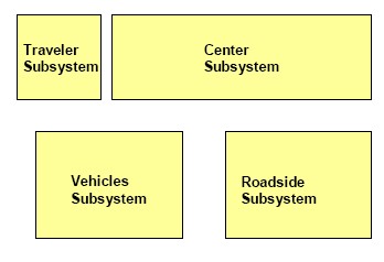
Under the National ITS Architecture the physical architecture contains facilities and infrastructure elements that are grouped into four classes of “subsystems”. The four classes of subsystems are identified as center, roadside, vehicle and traveler. Each class is described below using the definition adopted from the National ITS Architecture.
Center Subsystems provide management, administrative and support functions for the transportation system. The center subsystems each communicate with other centers to enable coordination between modes and across jurisdictions. The ten center subsystems are Traffic Management, Transit Management, Commercial Vehicle Administration, Archived Data Management, Emissions Management, Toll Administration, Emergency Management, Information Service Provider, Fleet and Freight Management and recently added Maintenance and Construction Management1. An example of a center subsystem could be the KC Scout Traffic Operations Center or the Gateway Guide Transportation Information Center.
Roadside Subsystems. Intelligent infrastructure distributed along the transportation network which perform surveillance, information provision and plan execution control functions and whose operation is governed by center subsystems. Direct interface to vehicle subsystems exist.2 An example of a roadside subsystem could be a variable message sign on the interstate.
Vehicle Subsystems cover ITS related elements on vehicle platforms. Vehicle subsystems include general driver information and safety systems applicable to all vehicle types. Four fleet vehicle subsystems (Transit, Emergency, Commercial Vehicles and the newly added Maintenance and Construction) add ITS capabilities unique to these special vehicle types.3 Examples of vehicle subsystems include automatic vehicle location systems on transit vehicles or the Emergency Response vehicles.
Traveler Subsystems are equipment used by travelers to access ITS services pre-trip and en route. This includes elements that are owned and operated by the traveler as well as elements that are owned by transportation and information providers.4 An example of a traveler subsystem could be an information kiosk at an airport.
Twenty-one different subsystems are organized under each of the four classes and defined under the National ITS Architecture. Each of the 21 subsystems corresponds to real-world elements such as a transit management facility, traffic controller, vehicle, or motorist.
- 1 USDOT, National ITS Architecture, Version 4.0, Physical Architecture, Center Subsystem
- 2 USDOT, National ITS Architecture, Version 4.0, Physical Architecture, Roadside Subsystem
- 3 USDOT, National ITS Architecture, Version 4.0, Physical Architecture, Vehicle Subsystem
- 4 USDOT, National ITS Architecture, Version 4.0, Physical Architecture, Traveler Subsystem
910.4.1.4.1.2 Terminators
Terminators represent the outer limits of the National ITS Architecture. In the physical architecture terminators function as boundaries for information exchanged. Typically terminators only interact with a single subsystem and to not link together multiple system elements similar to subsystems. There are four categories of terminators. These categories are environment, human, other system and system. An example of a terminator in the human category would be a traveler, or individual who uses transportation services. Or an example of a system terminator would be a specific state agency responsible for registering vehicles such a Department of Motor Vehicles (DMV).
910.4.1.4.1.3 Architecture Flows
Architecture Flows are the information exchanged between subsystems and terminators in the physical architecture. Architecture flows are the primary tool that is used to define regional architecture interfaces. These architecture flows and their communication requirements define the interfaces that form the basis for much of the ongoing standards work. An example of an information flow would be a statewide traffic information center requesting traffic information from a regional center such as KC Scout or Gateway Guide.
910.4.1.4.1.4 High Level Physical Architecture / Sausage Diagram
The “sausage diagram” is considered the high level interconnect diagram for the National ITS Architecture. It illustrates how different subsystems connect and the communication methods that facilitate the data exchanges between them. As a high level diagram it only shows the interconnection between different subsystems and does not provide specific details on the exact information and data exchanged.
910.4.1.4.1.5 Interconnect Diagram
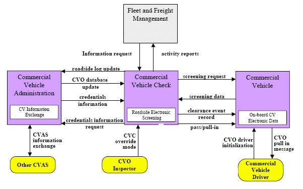
The interconnect diagram highlights the communication interaction between multiple subsystems or between a subsystem and terminators. The diagram details communication paths between the architecture elements showing how information is routed. The type of communications system reflected by the interconnect flow can be one of four types that include wireline, wide area wireless, dedicated short range or vehicle-to-vehicle. Additional communications types such as human and physical/environmental interfaces can also be represented by interconnect flows.
910.4.1.4.1.6 Architecture Flow Diagram
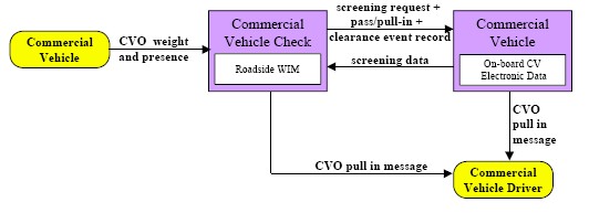
The architecture flow diagram further elaborates on the information provided by the interconnect flow diagram. Whereas, the interconnect diagram indicates the communication path between elements the architecture flow diagram details the information exchanged on that path. Typically a single interconnect flow represent one or more architecture flows which detail the type and direction information exchanges on the interconnect take between subsystems or terminators in the system.
910.4.1.4.1.7 Market Packages
A market package provides an accessible, service-oriented perspective to the National ITS Architecture. They are tailored to fit, separately or in combination, real world transportation problems and needs. Examples of market packages include: network surveillance, emergency response, and maintenance and construction vehicle tracking. Market packages are a collection of one or more groupings of implementable processes. These processes must work together to deliver a given transportation service and the architecture flows that connect them and other important external systems. In other words, they identify the pieces of the physical architecture that are required to implement a particular transportation service. There are currently 75 Market Packages included in the most recent version of the National ITS Architecture (Version 4.0) that was planned for mass public release in April 2002. The most significant impact to Missouri is the additional 10 market packages oriented to support Rural ITS services. Since Kansas City and St. Louis have existing Emergency Response Programs, the addition of the Roadway Service Patrol Market Package will have an impact on existing regional architectures. Additional discussion on Market Packages and their use in prioritizing core ITS Program Areas in Missouri is provided in EPG 910.4.3 Missouri ITS Program Areas.
910.4.1.4.2 Overview of Logical Architecture
Another architecture contained within the National ITS Architecture is referred to as the logical architecture. The logical architecture describes the functionality of an ITS system and details how user services are supported. It establishes the processes that execute the functionality and the information distributed between those processes. The logical architecture, like the physical architecture, does not mandate a particular technology for implementation, rather it allows for flexibility in system deployment.
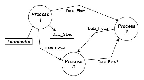
The Logical Architecture uses the following elements to define and illustrate system functionality: processes, process specifications, data flows, data dictionary entries and data flow diagrams.
The Missouri Statewide ITS Architecture drills down to the physical, interconnect level. However, the previously mentioned physical architecture elements can be further decomposed to develop a logical architecture. Thus, brief overviews of the elements comprising a logical architecture are presented for reference.
910.4.1.4.2.1 Processes
A process is a function or activity that is needed to support an ITS User Service. It is utilized in the logical architecture to represent high-level general actions and also more detailed functions. An example of how processes are used to represent general and specific functions can be demonstrated by looking at the general process “Manage Traffic” in the National ITS Architecture. The “Manage Traffic” process identified can be further broken down into the following more detailed processes specifying components of traffic to be managed:
- “Provide Traffic Surveillance”
- "Manage Incidents”
- “Provide Device Control”
- “Manage Emissions”
- “Manage Travel Demand”
- “Manage Highway Rail Intersections”
Each additional process can be further broken down until you reach “primitive processes” representing not only the lowest level process but also the most specific or detail function.
910.4.1.4.2.2 Process Specification
Process specifications are the most detailed processes defined by the logical architecture. Process specifications contain a description, list of functional requirements and a set of inputs and outputs, generally referenced as Pspec.
910.4.1.4.2.3 Data Flow
Data flows represent information exchanged between processes in the logical architecture. Data flows indicate the type and direction information travels between processes. Combinations of data flows are also used to define architecture flows deployed in the physical architecture. Individual data flows are generally defined in a data dictionary entry.
910.4.1.4.2.4 Data Dictionary Entries
A data dictionary is used in the logical architecture to describe a data flow’s characteristics. A data dictionary entry (DDE) contains a description of the data flow and highlights additional lower level data elements that are part of that flow. Lower level data elements are also define by separate DDEs.
910.4.1.4.2.5 Data Flow Diagram
The data flow diagram illustrates the processes and data exchanges in a logical architecture. The diagram consists of four elements each with a unique symbol. The functions or processes in the diagram are represented by circles and perform different architecture tasks. Lines with arrows indicate the movement of information or data between diagram elements and represent data flows. “Data at rest” in the system is represented by parallel lines and are referred to as data stores. The last diagram element is a terminator, which is represented by a rectangle and depicts an endpoint or boundary for the architecture.
910.4.1.5 Status of ITS Architecture Initiatives
Several ITS Architecture initiatives are being developed or have been completed in Missouri. Below is a brief description of various ITS Architecture related projects.
910.4.1.5.1 Kansas City Area
The Kansas City Metropolitan Region is developing a regional ITS architecture through the use of a Tier 2 Workshop lead by the National ITS Architecture Team in Kansas City. The Mid America Regional Council (MARC), the regional metropolitan planning organization, maintains the current database.
910.4.1.5.2 St. Louis Area
The St. Louis Metropolitan Region is developing a regional ITS architecture through the use of a Tier 2 Workshop lead by the National ITS Architecture Team in St. Louis. MoDOT District 6 personnel maintain the current database.
A project architecture to support the I-270/255 Corridor Project was also developed. The scope of the deployment project includes installation of five systems: Traffic Management System, Local Traffic Operations System, Local Emergency Response System, Transit Management System and Information Service Providers. The five systems are interrelated and contain subsystems that can also be interconnected within each system.
910.4.1.5.3 Springfield Area
The City of Springfield, in close cooperation with MoDOT, leads the development of the Regional ITS Architecture.
910.4.1.5.4 State Business Plan for CVISN
The State Business Plan for Commercial Vehicle Information Systems and Networks (CVISN) was completed in late 2000. The report includes the definition of several projects associated with Level 1 CVISN deployment in Missouri including a high level physical architecture. However, the physical architecture does not directly map to the National ITS Architecture and did not use the USDOT endorsed database-mapping tool (i.e., TurboArchitecture). CVISN activities are lead by Traffic.
910.4.1.6 Emerging National ITS Architecture Developments
A new version (Version 4.0) of the National ITS Architecture was ready for mass distribution in April 2002. While most regional and project ITS architecture have been developed using Version 3.0 as a base, the statewide architecture has captured some of the key enhancements provided in Version 4.0. Some of the major enhancements to Version 4.0 that impact the statewide architecture include:
- Addition of the Maintenance and Construction Service Area. New market packages directly related to providing maintenance and construction services have been added. The 10 new Market Packages include:
- maintenance and construction vehicle tracking
- maintenance and construction vehicle maintenance
- road weather data collection
- weather information processing and distribution
- roadway automated treatment
- winter maintenance
- roadway maintenance and construction
- work zone management
- work zone safety monitoring
- maintenance and construction activity coordination
- Enhanced Weather Coverage. An overarching view of weather information in the National ITS Architecture was created through defining two market packages (Road Weather Data Collection and Weather Information Processing and Dissemination) that encompass all aspects of weather information in the architecture. In addition, the architecture flows relating to weather were expanded to provide a more complete view of this important area.
- Improved Rural User Needs Coverage. Changes and additions have been made to the architecture to satisfy the "Rural User Needs" requirements in the industry. Areas of the architecture affected include the creation of a new terminator called the "Care Facility" and enhancing remote area surveillance to include rest areas, park and ride lots, emergency pull-off areas, etc.
- Roadway Service Patrols Coverage. Additions have been made to the architecture to accommodate an increased use of roadway service patrols throughout the country. The new market package accurately encompasses the existing functions of the Emergency Response Patrol in Kansas City and St. Louis.
910.4.2 Missouri High Level Physical Architecture
910.4.2.1 Geographical Limits of ITS Architecture
The geographical limits of the Missouri Statewide ITS Architecture include the entire state and the metropolitan areas of Kansas City and St. Louis extending into Kansas and Illinois, respectively. Missouri’s highway system is more than 32,000 miles long, the nation’s seventh-largest state highway system.5 Missouri is also coordinates with eight neighboring states.
- 5 Missouri Department of Transportation 2000 Annual Report, pg. 14.
910.4.2.2 Participating Agencies and Other Stakeholders
The regional architectures developed for Kansas City and St. Louis metropolitan areas generated databases with hundreds of participating agencies and stakeholders. The purpose of the Statewide ITS Architecture is to document relationship between agencies that provide services that are statewide in nature or have regional significance. Therefore, instead of recreating every municipality in the regional architectures, the statewide architecture has generalized the county and municipal services. The stakeholders reflected in the Statewide ITS Architecture are:
| MoDOT Central Office | MoDOT district offices |
| Kansas City Scout | St. Louis Gateway Guide |
| Statewide Traffic Operations Center | Springfield Traffic Management System |
| Branson TMC and TRIP | KDOT Metro Operations Area |
| IDOT St. Louis Area Traveler Information Center | MoDOT Emergency Response |
| Missouri State Highway Patrol | Metro Traffic Networks |
| County Public Works | Municipal Public Works |
| County Public Safety | Municipal Public Safety |
| Bi-State Development Agency (St. Louis) | Kansas City Area Transit Authority |
| OATS, Inc. | Federal Motor Carrier Safety Administration |
| Southern Missouri Trans. Systems (STMS), Inc. | Missouri Dept. of Revenue – Highway Reciprocity Commission |
| MoDOT Motor Carrier Services Unit | Missouri State Highway Patrol Commercial Vehicle Inspection Unit |
| Commercial Trucking Companies | Missouri Dept. of Economic Development Division of Motor Carrier and Rail Safety |
| International Registration Plan, Inc. | International Fuel Tax Association |
| Missouri Dept. of Natural Resources | Mid-America Regional Council (Kansas City) |
| Kansas City Police Dept. | St. Louis Police Dept. |
910.4.2.3 High Level Physical Architecture Diagram (i.e., Sausage Diagram)
Systems have been categorized into four deployment status categories: existing, proposed/in progress, short-term and medium/long term. The short and medium/long term subsystem were developed to support the core ITS Program Areas further discussed in Section 4 of the report.
910.4.3 Missouri ITS Program Areas
910.4.3.1 Background and Development of CORE ITS Program Areas
To clarify on which ITS-related businesses MoDOT should focus, several core ITS Programs have been developed. The core ITS Program areas were developed based on results from the Market Package Prioritization Tool. Each Market Package was prioritized based on five different deployment settings: urban, semi-urban, rural, corridor and statewide. The core ITS Program development process, which is an extension of the physical ITS architecture development process shown previously in Figure 910.4.1.4.1, is further illustrated in Figure 910.4.3.1.
Results of the prioritization were screened and market packages scoring in the top 30% of the assessment were grouped in the following logical program areas:
- Commercial Vehicle Operations
- Incident Management
- Traffic Control and Monitoring
- Traveler and Weather Information
- Transit Management
- Emergency Management and MCO
For additional information in the results if the market package prioritization, see the Market Package Report. The market prioritization presented here in the development of this statewide architecture is for a time captured in August 2001. The statewide plan and architecture are dynamic documents as advancements in deployment occur in Missouri. The architecture presented here will require routine maintenance by MoDOT as revisions occur using the prioritization tool and deployments advance.
910.4.3.2 Description and Market Package Composition of Each Program Area
The following sections provide a summary of the proposed market packages for deployment consideration throughout Missouri (i.e., deployment setting) and definitions of each market package composing the core ITS Program Areas.
910.4.3.2.1 Commercial Vehicle Operations (CVO)
The Commercial Vehicle Operations ITS Program is composed of the following three market packages and associated deployment areas/settings:
- Electronic Clearance, Statewide
- Weigh In Motion, Statewide
- Commercial Vehicle Administrative Process, Statewide
For reference purposes, definitions of each market package are provided below: Electronic Clearance Market Package Definition. This market package provides for automated clearance at roadside check facilities. The roadside check facility communicates with the Commercial Vehicle Administration subsystem over wireline to retrieve infrastructure snapshots of critical carrier, vehicle, and driver data to be used to sort passing vehicles. This package allows a good driver/vehicle/carrier to pass roadside facilities at highway speeds using transponders and dedicated short-range communications to the roadside. The roadside check facility may be equipped with AVI, weighing sensors, transponder read/write devices, computer workstation processing hardware, software and databases.
Weigh In Motion Market Package Definition. This market package provides for high speed weigh-in-motion with or without AVI attachment. Primarily this market package provides the roadside with additional equipment, either fixed or removable. If the equipment is fixed, then it is thought to be an addition to the electronic clearance and would work in conjunction with the AVI and AVC equipment in place.
Commercial Vehicle Administrative Process Definition. This market package provides for electronic application, processing, fee collection, issuance, and distribution of CVO credential and tax filing. Through this process, carriers, drivers, and vehicles may be enrolled in the electronic clearance program provided by a separate market package which allows commercial vehicles to be screened at mainline speeds at commercial vehicle check points. Through this enrollment process, current profile databases are maintained in the Commercial Vehicle Administration Subsystem and snapshots of this database are made available to the commercial vehicle check facilities at the roadside to support the electronic clearance process.
910.4.3.2.2 Incident Management
| I-64 Project |
| Evaluation of Arterial Service Patrol Programs |
| See also: Innovation Library |
The Incident Management ITS Program is composed of the following four market packages and associated deployment areas/settings:
- Incident Management, Urban, Semi-Urban, Corridor, Statewide
- Emergency Response, Urban
- Emergency Routing, Urban
- Roadway Service Patrols, Urban
The Roadway Service Patrol Market Package was not part of the initial Market Package Assessment since it has only recently been released as part of Version 4.0 of the National ITS Architecture. However, since existing, and very successful, Emergency Response Patrols operate in the Kansas City and St. Louis areas, the new market package has been added to the Incident Management Program Area. During the next iteration of using the Prioritization Tool, it is extremely likely the Roadway Service Patrol market package will score very high. For reference purposes, definitions of each market package are provided below:
Incident Management Market Package Definition. This market package manages both predicted and unexpected incidents so that the impact to the transportation network and traveler safety is minimized. Requisite incident detection capabilities are included in the freeway control market package and through the regional coordination with other traffic management and emergency management centers, weather service entities, and event promoters supported by this market package. Information from these diverse sources are collected and correlated by this market package to detect and verify incidents and implement an appropriate response. This market package provides Traffic Management Subsystem equipment that supports traffic operations personnel in developing an appropriate response in coordination with emergency management and other incident response personnel to confirmed incidents. The response may include traffic control strategy modifications and presentation of information to affected travelers using the Traffic Information Dissemination market package. The same equipment assists the operator by monitoring incident status as the response unfolds. The coordination with emergency management might be through a CAD system or through other communication with emergency field personnel. The coordination can also extend to tow trucks and other field service personnel.
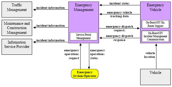
Emergency Response Market Package Definition. This market package provides the computer-aided dispatch systems, emergency vehicle equipment, and wireless communications that enable safe and rapid deployment of appropriate resources to an emergency. Coordination between Emergency Management Subsystems supports emergency notification and coordinated response between agencies. Existing wide area wireless communications would be utilized between the Emergency Management Subsystem and an Emergency Vehicle to enable an incident command system to be established and supported at the emergency location. The Emergency Management Subsystem would include hardware and software for tracking the emergency vehicles. Public safety, traffic management and many other allied agencies may each participate in the coordinated response managed by this package.
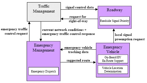
Emergency Routing Market Package Definition. This market package supports dynamic routing of emergency vehicles and coordination with the Traffic Management Subsystem for special priority on the selected route(s). The Information Service Provider Subsystem supports routing for the emergency fleet based on real-time traffic conditions and the emergency routes assigned to other responding vehicles. In this market package, the Information Service Provider Subsystem would typically be integrated with the Emergency Management Subsystem in a public safety communications center. The Emergency Vehicle would also optionally be equipped with dedicated short-range communications for local signal preemption.
Roadway Service Patrol Market Package Definition. This market package supports roadway service patrol vehicles that monitor roads that typically have incidents, offering rapid response to minor incidents (flat tire, accidents, out of gas) and support for major incidents to minimize disruption to the traffic stream. If problems are detected, the roadway service patrol vehicles will provide assistance to the motorist (e.g., push a vehicle to the shoulder or median).
910.4.3.2.3 Traffic Control and Monitoring
The Traffic Control and Monitoring ITS Program is composed of the following three market packages and associated deployment areas/settings:
- Freeway Control, Urban
- Surface Street Control, Urban, Semi-Urban
- Network Surveillance, Urban, Semi-Urban
For reference purposes, definitions of each market package are provided below:
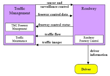
Freeway Control Market Package Definition. This market package provides the communications and roadside equipment to support ramp control, lane controls, and interchange control for freeways. Coordination and integration of ramp meters are included as part of this market package. This package is consistent with typical urban traffic freeway control systems. This package incorporates the instrumentation included in the Network Surveillance Market Package to support freeway monitoring and adaptive strategies as an option. This market package also includes the capability to utilize surveillance information for detection of incidents. Typically, the processing would be performed at a traffic management center; however, developments might allow for point detection with roadway equipment. For example, a CCTV might include the capability to detect an incident based upon image changes. Additionally, this market package allows general advisory and traffic control information to be provided to the driver while en route.
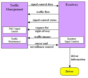
Surface Street Control Market Package Definition. This market package provides the central control and monitoring equipment, communication links, and the signal control equipment that support local surface street control and/or arterial traffic management. A range of traffic signal control systems are represented by this market package ranging from static pre-timed control systems to fully traffic responsive systems that dynamically adjust control plans and strategies based on current traffic conditions and priority requests. Additionally, general advisory and traffic control information can be provided to the driver while en route. This market package is generally an intrajurisdictional package that typically does not rely on real-time communications between separate control systems to achieve area-wide traffic signal coordination. Systems that achieve coordination across jurisdictions by using a common time base or other strategies that do not require real time coordination would be represented by this package. This market package is consistent with typical urban traffic signal control systems.
Network Surveillance Market Package Definition. This Market Package includes traffic detectors, environmental sensors, other surveillance equipment, the supporting field equipment, and wireline communications to transmit the collected data back to the Traffic Management Subsystem. The derived data can be used locally such as when traffic detectors are connected directly to a signal control system or remotely (e.g., when a CCTV system sends data back to the Traffic Management Subsystem). The data generated by this Market Package enables traffic managers to monitor traffic and road conditions, identify and verify incidents, detect faults in indicator operations, and collect census data for traffic strategy development and long range planning. The collected data can also be analyzed and made available to users and the Information Service Provider Subsystem.
910.4.3.2.4 Traveler and Weather Information
The Traffic Control and Monitoring ITS Program is composed of the following three market packages and associated deployment areas/settings:
- Broadcast Traveler Information, Urban, Semi-Urban
- Traffic Information Dissemination, Semi-Urban
- Road Weather Information Systems, Urban, Semi-Urban, Corridor, Statewide
For reference purposes, definitions of each market package are provided below:
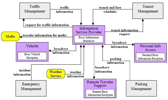
Broadcast Traveler Information Market Package Definition. This market package provides the user with a basic set of ATIS services; its objective is early acceptance. It involves the collection of traffic conditions, advisories, general public transportation, toll and parking information, incident information, air quality and weather information, and the near real time dissemination of this information over a wide area through existing infrastructures and low cost user equipment (e.g., FM subcarrier, cellular data broadcast). Different from the market package ATMS6, Traffic Information Dissemination, that provides the more basic HAR and DMS information capabilities, ATIS1 provides the more sophisticated digital broadcast service. Successful deployment of this market package relies on availability of real-time traveler information from roadway instrumentation, probe vehicles or other sources.
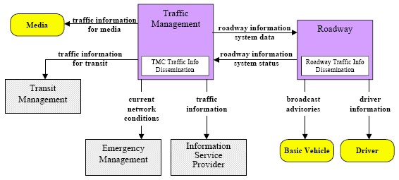
Traffic Information Dissemination Market Package Definition. This market package allows traffic information to be disseminated to drivers and vehicles using roadway equipment such as dynamic message signs or highway advisory radio. This package provides a tool that can be used to notify drivers of incidents; careful placement of the roadway equipment provides the information at points in the network where the drivers have recourse and can tailor their routes to account for the new information. This package also covers the equipment and interfaces that provide traffic information from a traffic management center to the media (for instance via a direct tie-in between a traffic management center and radio or television station computer systems), 511 systems, transit management center, emergency management center and information service provider.
Road Weather Information System, Market Package Definition. This market package monitors current and forecast road and weather conditions using a combination of weather service information and data collected from environmental sensors deployed on and about the roadway. The collected road weather information is monitored and analyzed to detect and forecast environmental hazards such as icy road conditions, dense fog, and approaching severe weather fronts. This information can be used to more effectively deploy road maintenance resources, issue general traveler advisories, and support location specific warnings to drivers using the Traffic Information Dissemination Market Package.
910.4.3.2.5 Transit Management
The Traffic Control and Monitoring ITS Program is composed of the following two market packages and associated deployment areas/settings:
- Transit Vehicle Tracking, Urban, Semi-Urban and Rural
- Transit Fixed Route Operations, Urban
For reference purposes, definitions of each market package are provided below:
Transit Vehicle Tracking Market Package Definition. This market package provides for an Automated Vehicle Location System to track the transit vehicle’s real time schedule adherence and updates the transit system’s schedule in real-time. Vehicle position may be determined either by the vehicle (e.g., through GPS) and relayed to the infrastructure or may be determined directly by the communications infrastructure. A two-way wireless communication link with the Transit Management Subsystem is used for relaying vehicle position and control measures. Fixed route transit systems may also employ beacons along the route to enable position determination and facilitate communications with each vehicle at fixed intervals. The Transit Management Subsystem processes this information, updates the transit schedule and makes real-time schedule information available to the Information Service Provider Subsystem via a wireline link.
Transit Fixed Route Operations Market Package Definition. This market package performs automatic driver assignment and monitoring, as well as vehicle routing and scheduling for fixed-route services. This service uses the existing AVL database as a source for current schedule performance data, and is implemented through data processing and information display at the transit management subsystem. This data is exchanged using the existing wireline link to the information service provider where it is integrated with that from other transportation modes (e.g. rail, ferry, air) to provide the public with integrated and personalized dynamic schedules.
910.4.4 Operational Concept
The Missouri Statewide ITS concept of operations provides a general outline of roles and responsibilities for agencies that will be significantly impacted by the core ITS Program Areas. The information provided in this section should be used to refine existing and future agreements between stakeholder agencies. For each core ITS Program area, a roles and responsibilities matrix and physical architecture interconnect diagrams have been developed.
910.4.4.1 Program Area Roles and Responsibilities
A clear understanding of roles and responsibilities is critical to any transportation related program or project particularly when technology is involved. The following matrices attempt to clarify agency roles and responsibilities associated with the core ITS Program Areas. Roles and responsibilities have generally been categorized into three areas: costs, operations and maintenance.
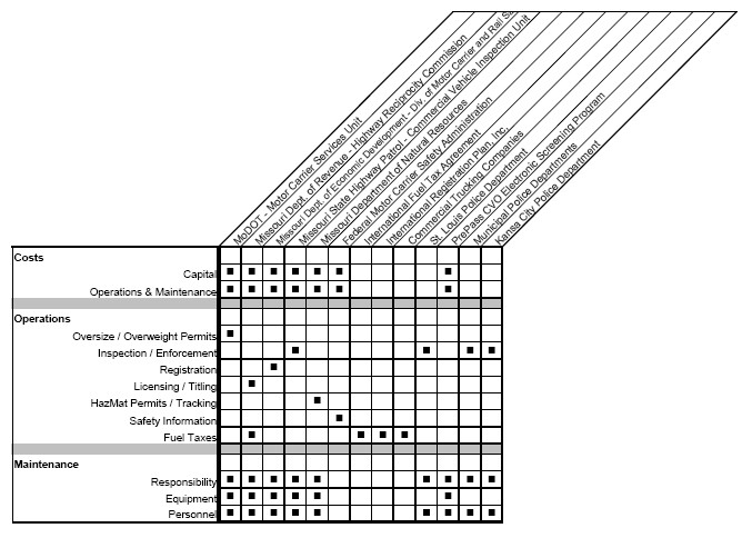
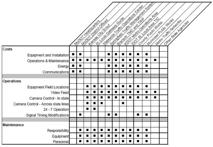
910.4.4.1.1 Commercial Vehicle Operations (CVO) Roles and Responsibilities
The chart below shows the recommended Commercial Vehicle Operations Roles and Responsibilities Matrix. The matrix was developed based on the Missouri CVISN Business and Program Plan.
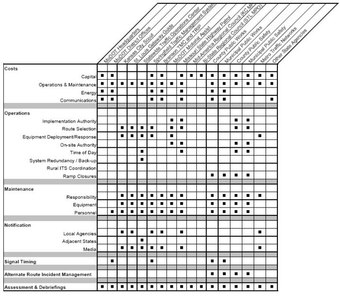
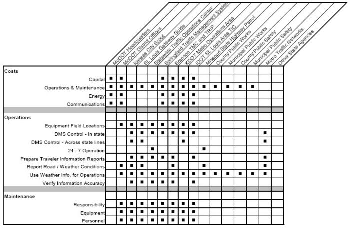
910.4.4.1.2 Incident Management Roles and Responsibilities
The chart below shows the recommended Incident Management Roles and Responsibilities Matrix. The matrix was developed based on the Baseline Assessment Report.
910.4.4.1.3 Traffic Control and Monitoring Roles and Responsibilities
The chart below shows the Traffic Control and Monitoring Roles and Responsibilities Matrix. The matrix was developed based on the Baseline Assessment Report.
910.4.4.1.4 Traveler and Weather Information Roles and Responsibilities
The chart below shows the recommended Traveler and Weather Information Roles and Responsibilities Matrix. The matrix was developed based on the Baseline Assessment Report and regional architectures for Kansas City and St. Louis.
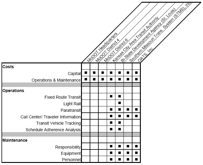
910.4.4.1.5 Transit Management Roles and Responsibilities
The chart below shows the recommended Transit Management Roles and Responsibilities Matrix. The matrix was developed based on the Baseline Assessment Report and regional architectures of Kansas City and St. Louis.
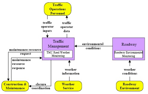
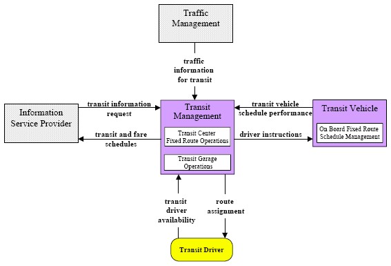
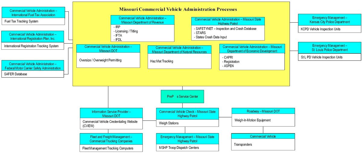
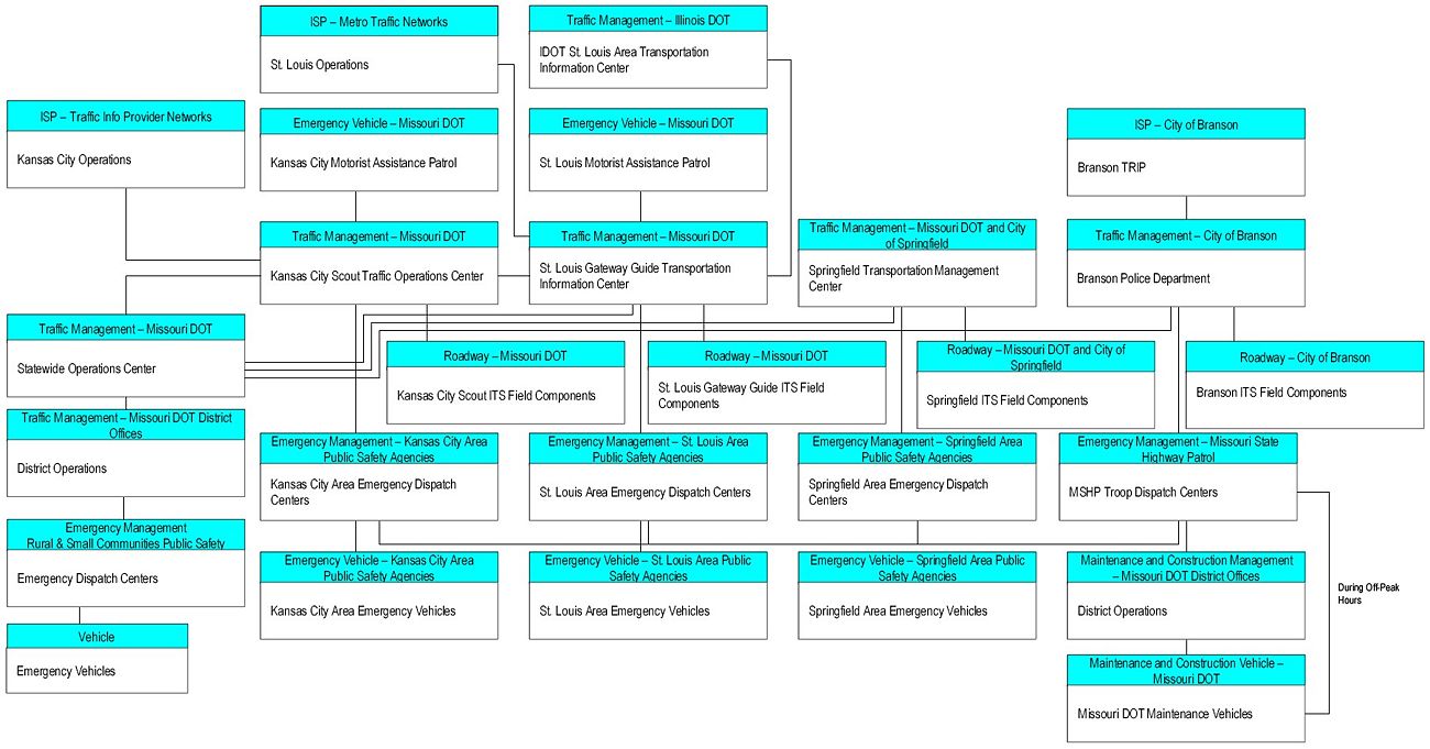
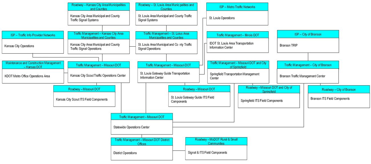
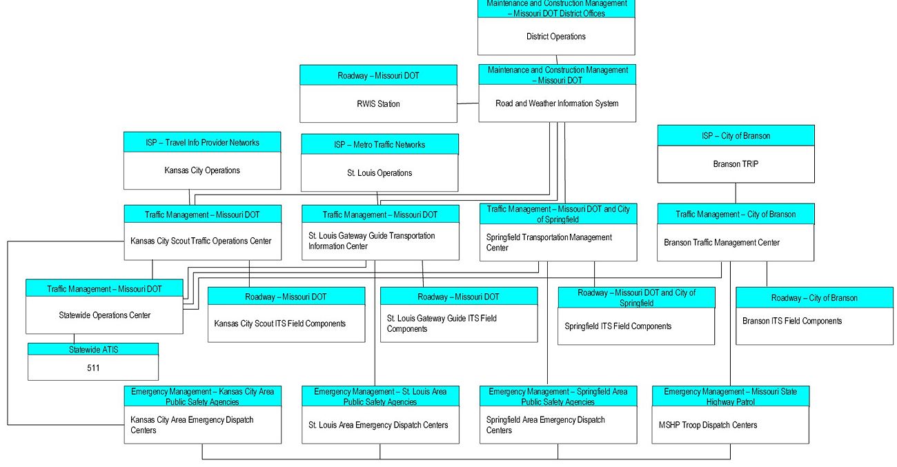
910.4.4.2 Physical Architecture Subsystem Interconnect Diagrams
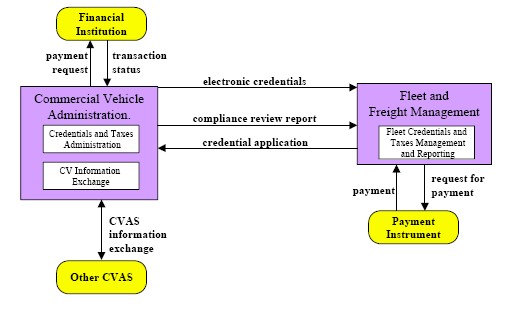
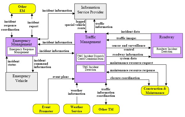
Understanding the “real world” relationship between agencies can be depicted using physical architecture interconnect diagrams. The interconnect diagram serves as a good screening tool by providing a block drawing with undefined connectors. Planners and engineers can easily determine what agencies are, or should be, connected to one another without drilling into too much architecture flow level detail. The following sections provide subsystem interconnect diagrams associated with each core ITS Program Areas.
910.4.5 ITS Standards
This article introduces the National Transportation Communications ITS Protocol (NTCIP) standards and addresses the benefits of implementing NTCIP and other standards. Each core ITS Program Area has been mapped to appropriate NTCIP standards to provide a guide to standards that must be considered when planning for and deploying future projects.
NTCIP is a family of standards that provides both the rules for communicating (called protocols) and the vocabulary (called objects) necessary to allow electronic traffic control equipment from different manufacturers to operate with each other as a system. NTCIP is the first set of standards for the transportation industry that allows traffic control systems to be built using a "mix and match" approach with equipment from different manufacturers. Therefore, NTCIP standards reduce the need for reliance on specific equipment vendors and customized one-of-a-kind software. To assure both manufacturer and user community support, NTCIP is jointly developed by NEMA, AASHTO and ITE.
An ITS standard undergoes several steps prior to formal adoption. The process typically can take one to five years. Figure 910.4.5 illustrates the Life Cycle of ITS Standards which are generally broken into four categories including Standard Development, Standard Testing, ITS Product Development and Standard Adoption.
| SDO develops, approves and publishes standard | Standard is tested | Standard matures and ITS products are developed | Adoption of standard through U.S. DOT rulemaking | |||
|---|---|---|---|---|---|---|
| Standards development organizations (SDOs) coordinate the development of standards. 1) During development, an SDO committee writes and documents the technical aspects of standards. 2) Standards then go through a balloting process where committee or working group members review the technical merits of the standards. A standard may or may not pass balloting. 3) Standards that have passed all necessary ballots are approved. At this stage, the standard can be used but is not yet published. 4) Approved standards are published by the SDO and are available for purchase. |
Testing measures the operation, correctness and completeness of a standard under realistic transportation operating conditions. It also measures the degree of interoperability (the capacity of a device to communicate with different types of ITS devices) among standards as well as provides information about the performance of a standard to the ITS community. | As standards mature, competition develops among vendors to provide a range of equipment with differing levels of functionality. This gives transportation managers greater flexibility in choosing products that best suit their particular project requirements. Standardized components lead to interoperability and interchangeability (the capacity to substitute one manufacturer's device for another). ITS devices, based on open standards, lead to cost savings, as well as to easier and more efficient systems maintenance and operations. |
Not all ITS standards reach this stage. The U.S. DOT will only consider adopting an ITS standard through rulemaking if the standard meets, at a minimum, certain established criteria. These criteria are defined in the Final Rule/Policy on the National ITS Architecture and ITS Standards and are intended to produce technically and commercially viable ITS standards and equipment. |
- 6 “Life Cycle of ITS Standards”, Publication No. FHWA-OP-01-047, May 2001
910.4.5.1 USDOT Position on Implementing ITS Standards
The Transportation Equity Act for the 21st Century (TEA-21) required the United States Department of Transportation (USDOT) to identify a set of “Critical ITS Standards” to focus USDOT’s ITS efforts. USDOT developed a list of thirteen critical standards, which includes NTCIP. The Federal Highway Administration (FHWA) Rule on ITS Architecture and Standards requires that agencies receiving federal funds for ITS use USDOT-adopted standards. As of 2002, USDOT had not adopted any standards and agencies were not explicitly required to use ITS standards. A formal rule-making process will be conducted when USDOT intends to implement ITS Standards. It is likely that USDOT will adopt ITS standards from time to time over the next decade.
910.4.5.2 Benefits of ITS Standards
The benefits of any ITS standards-based implementation are very difficult to quantify, particularly for a single ITS standard. However, the adoption of ITS standards is an essential part of implementing statewide and/or regional ITS architectures. Standards are the glue that bonds the various parts of the identified architecture together to enable automated data exchanges. Many of the benefits will be found in the long-term operational and maintenance aspects of system deployments. These benefits are still being quantified, as the standards are still very new or still being developed. ITS standards help to achieve the overall goals of an ITS program.
One of the greatest benefits of acquiring and installing NTCIP-based systems is that they enable systems to “talk” to each other. This possibility of communications is achieved on both levels: center-to-field as well as center-to-center links. Without common ITS standards, proprietary protocols need to be developed and used by vendors and system integrators. These proprietary protocols are mostly application-specific and are developed to be very efficient. However commonality and/or flexibility to address other vendor’s equipment needs were neither considered nor desired. NTCIP standards are an enabling building block for helping to solve the historical challenges involved with implementation, operations, and maintenance. The benefits of these standards include:
- Reduction or even elimination of dependency on single vendor’s system components – This does not mean that an agency cannot retain a preferred vendor, but opens the door to competition and reduces price.
- Simplified system integration – Common functionalities among device types allow one central software to control and monitor devices from different vendors, using the same communications and graphical user interface (GUI) software package.
- Capability to seamlessly transition multi-jurisdictional systems – Common functionalities allow neighboring agencies to monitor and even control (assuming appropriate authorization) each other’s field equipment.
- Reduction in infrastructure investments – The ITS standards were designed to allow compatibility of different device types. The commonality of the supporting communications protocol standards allows several end-applications, such as signal controllers, DMS, and Highway Advisory Radio (HAR), to use the same communications infrastructure. In the past, each proprietary protocol required a separate communications line.
- Support ease of expandability – The Standards were also designed to be flexible, allowing easy additions to the standards in terms of adding functionalities. Both the standards development organizations, and vendors can add these functionalities.
- Reduction in system engineering cost – Due to the ease of expandability and common interfaces to common functionalities, integration and system engineering costs will be reduced.
- Expansion of knowledge base – The promotion and growing number of ITS standards-based implementations increase the number of people in public agencies and private companies that have gained the knowledge to guide and support ITS standards-based systems.
- Reduced maintenance training costs – Staff does not need continual training in various communications standards that are supported by a variety of devices.
- Less obsolescence – Once an interface to a particular device type (e.g., DMS) has been developed which addresses all of the user’s functional requirements, this interface software can be used for any DMS from any vendor (assuming all DMSs implement the same functional requirements using the same data elements as defined by the procuring agency).
910.4.5.3 Program Area Standards
Looking at the ITS Standards as a foundation for building the systems identified in the Missouri Statewide Architecture, Table 910.4.5.3 highlights applicable standards associated with the core ITS Program Areas and indicates status as of 2002.
Status is defined in Table 910.4.5.3 as:
- Published (P) - Standards available for purchase
- Approved (A) - Standards passing all necessary ballots and approved by a standards development organization but not yet published.
- In Balloting (IB) - Standards being voted upon by a committee or working group or are undergoing other SDO procedures
- Under Development (UD) - Standards being written but not yet ready for a formal ballot
Table 910.4.5.3 Program Area Standards
| SDO | Standard Number | Standard Name | Core ITS Program Area | Status as of 2002 | ||||
|---|---|---|---|---|---|---|---|---|
| Commercial Vehicle Operations | Incident Management | Traffic Control and Monitoring | Traveler and Weather Information Standards | Transit Management | ||||
| ANSI | TS285 | Commercial Vehicle Safety and Credentials Information Exchange | Y | - | - | - | - | P |
| ANSI | TS286 | Commercial Vehicle Credential | Y | - | - | - | - | P |
| ASTM | - | DSRC at 5.9 GHz | Y | - | - | - | - | P |
| SAE | J1764 | ISP – Vehicle Location Referencing Standard | - | - | - | Y | - | P |
| SAE | J2353 | Advanced Traveler Information System (ATIS) Data Dictionary | Y | Y | Y | Y | Y | P |
| SAE | J2354 | Advanced Traveler Information System (ATIS) Message Set | Y | Y | Y | Y | Y | P |
| SAE | J2369 | Standards for ATIS Message Sets Delivered Over Bandwidth Restricted Media | - | - | - | Y | - | P |
| SAE | J2529 | Rules for Standardizing Street Names and Route IDs | Y | Y | Y | Y | Y | P |
| SAE | J2540 | Messages for Handling Strings and Look-up Tables in ATIS Standards | Y | Y | Y | Y | Y | P |
| ITE | ITE-9603-3 | Advanced Transportation Controller (ATC) | - | Y | Y | Y | - | UD |
| ITE | ITE-9603-2 | ATC Cabinet | - | Y | Y | Y | - | UD |
| ITE | ITE-9603-1 | ATC Application Program Interface (API) | - | Y | Y | Y | - | UD |
| EIA/CEA | EIA-795 | Subcarrier Traffic Information (STIC) System | - | - | - | Y | - | P |
| EIA/CEA | EIA-794 | Data Radio Channel (DARC) System | - | - | - | Y | - | P |
| ASTM | PS105-99 | Standard Specification for DSRC – Data Link Layer | Y | Y | - | - | - | P |
| ASTM | PS111-98 | Standard Specification for DSRC – Physical Layer 902-928 MHz | Y | Y | - | - | - | P |
| ITE | TM 1.03 | Standard for Functional Level Traffic Management Data Dictionary (TMDD) | Y | Y | Y | - | Y | IB |
| ITE | TM 2.01 | Message Set for External TMC Communication (MS/ETMCC) | Y | Y | Y | - | Y | IB |
| AASHTO | TS 3.HAR | NTCIP – Object Definitions for Highway Advisory Radio (HAR) | - | Y | - | Y | - | UD |
| AASHTO | 1101 | NTCIP – Simple Transportation Management Framework (STMF) | - | Y | Y | Y | - | P |
| AASHTO | 1102 | NTCIP – Octet Encoding Rules | Y | Y | - | Y | Y | IB |
| AASHTO | 1103 | NTCIP – Simple Transportation Management (STMP) | - | Y | Y | Y | - | UD |
| AASHTO | 1104 | NTCIP – CORBA Naming Convention | Y | Y | Y | Y | Y | P |
| AASHTO | 1105 | NTCIP – CORBA Security Service | Y | Y | Y | Y | Y | P |
| AASHTO | 1106 | NTCIP – Near-Real Time Data Service | Y | Y | Y | Y | Y | P |
| AASHTO | 1201 | NTCIP – Global Object Definitions | Y | Y | Y | Y | Y | P |
| AASHTO | 1202 | NTCIP – Object Definitions for Actuated Traffic Signal Controller Units | - | Y | - | - | - | P |
| AASHTO | 1203 | NTCIP – Object Definitions for Dynamic Message Signs | - | - | - | Y | - | P |
| AASHTO | 1204 | NTCIP – Object Definitions for Environmental Sensor Stations | - | - | - | Y | - | P |
| AASHTO | 1205 | NTCIP – Object Definitions for Closed Circuit Television Camera Control | - | Y | Y | - | - | IB |
| AASHTO | 1206 | NTCIP – Data Collection and Monitoring Devices | - | - | Y | - | - | UD |
| AASHTO | 1207 | NTCIP – Object Definitions for Ramp Meter Control | - | - | Y | - | - | A |
| AASHTO | 1208 | NTCIP – Object Definitions for Video Switches | - | Y | Y | - | - | UD |
| AASHTO | 1209 | NTCIP – Object Definitions for Transportation Sensor Systems | - | Y | Y | - | - | UD |
| AASHTO | 1210 | NTCIP – Objects for Signal System Master | - | Y | Y | - | - | IB |
| AASHTO | 1211 | NTCIP – Objects for Signal Control Priority | - | Y | - | - | - | UD |
| AASHTO | 1301 | NTCIP – Message Sets for Weather Reports | - | Y | - | - | Y | UD |
| ITE | 1401 | TCIP – Common Public Transportation (CPT) Objects | - | - | - | - | Y | P |
| ITE | 1402 | TCIP – Incident Management (IM) Objects | - | Y | - | - | Y | P |
| ITE | 1403 | TCIP – Passenger Information (PI) Objects | - | - | - | - | Y | P |
| ITE | 1404 | TCIP – Scheduling/Runcutting (SCH) Objects | - | - | - | - | Y | P |
| ITE | 1405 | TCIP – Spatial Representation (SP) Objects | - | - | - | - | Y | P |
| ITE | 1406 | TCIP – Onboard (OB) Objects | - | - | - | - | Y | A |
| ITE | 1407 | TCIP – Control Center (CC) Objects | - | - | - | - | Y | A |
| IEEE | 1455 | Message Sets for DSRC ETTM and CVO | Y | - | - | - | - | P |
| IEEE | 1521.1 | Standard for Traffic Incident Management Message Sets for use by EMCs | - | Y | - | - | - | UD |
| IEEE | 1521.2 | Standard for Public Safety IMMS for use by EMCs | - | Y | - | - | - | UD |
| IEEE | 1521.3 | Standard for Hazardous Material IMMS for use by EMCs | - | Y | - | - | - | UD |
| IEEE | 1512.a | Standard for Emergency Management Data Dictionary | - | Y | - | Y | - | UD |
| IEEE | 1512-2000 | Standard for Common Incident Management Message Sets (IMMS) for use by EMCs | - | Y | - | Y | - | P |
| IEEE | 1556 | Security/Privacy of Vehicle/RS Communications including Smart Card Communications | Y | Y | - | - | - | UD |
| AASHTO | 2001 | NTCIP – Class B Profile | - | - | Y | - | - | P |
| AASHTO | 2101 | NTCIP – Point-to-Multipoint Protocol/RS232 Subnetwork Profile | - | Y | Y | Y | - | A |
| AASHTO | 2102 | NTCIP – Subnet Profile for PMPP over FSK modems | - | - | Y | Y | Y | A |
| AASHTO | 2103 | NTCIP – Subnetwork Profile for Point-to-Point using RS232 | - | Y | Y | Y | - | UD |
| AASHTO | 2104 | NTCIP – Subnetwork Profile for Ethernet | Y | Y | Y | Y | Y | IB |
| AASHTO | 2201 | NTCIP – Transportation Transport Profile | - | Y | Y | Y | - | A |
| AASHTO | 2202 | NTCIP – Internet (TCP/IP and UDP/IP) Transport Profiles | Y | Y | Y | Y | Y | A |
| AASHTO | 2301 | NTCIP – STMF Application Profile | - | Y | Y | Y | - | A |
| AASHTO | 2302 | NTCIP – Trivial File Transfer Protocol - Application Profile | - | Y | Y | Y | - | A |
| AASHTO | 2303 | NTCIP – File Transfer Protocol - Application Profile | Y | Y | Y | Y | Y | A |
| AASHTO | 2304 | NTCIP – Application Profile – Data Exchange (DATEX) | Y | Y | Y | Y | Y | IB |
| AASHTO | 2305 | NTCIP – Application Profile - CORBA | Y | Y | Y | Y | Y | UD |
| AASHTO | 2501 | NTCIP – Information Profile for DATEX | Y | Y | Y | Y | Y | A |
| AASHTO | 2502 | NTCIP – Information Profile for DATEX | Y | Y | Y | Y | Y | A |
910.4.6 Sequence of Statewide ITS Program Areas
Figure 910.4.6 shows a proposed schedule of how the ITS Program Areas should be implemented over a 15-year horizon. The Incident Management Program and Traffic Control and Monitoring Areas have the longest implementation period to take into considerations anticipated advancements in communications and information technology, the complexity of inter-agency coordination, and the extensive size of the Missouri highway system.
910.4.7 Acronym List and Websites
| AASHTO | American Association of State Highway Transportation Agencies |
| ANSI | American National Standards Institute |
| ATC | Advanced Transportation Controller |
| ATIS | Advanced Traveler Information System |
| AVI | Automatic Vehicle Identification |
| C2C | Task C2C |
| CAD | Computer-Aided Dispatch |
| CEA | Consumer Electronics Association |
| CC | Control Center |
| CCTV | Closed Circuit Television Cameras |
| CDPD | Cellular Digital Packet Data |
| CORBA | Common Object Request Broker Architecture |
| CPT | Common Public Transportation |
| CVISN | Commercial Vehicle Information Systems and Networks |
| DATEX | Data Exchange |
| DATEX ASN | Data Exchange ASN 1 |
| DDE | Data Dictionary Entry |
| DMS | Dynamic Message Sign |
| DSRC | Dedicated Short Range Communications |
| DTI | Digital Teleport, Incorporated |
| ESS | Environmental Sensor Stations |
| EIA | Electronic Industries Alliance |
| FC | Fare Collection |
| FCC | Federal Communications Commission |
| FHWA | Federal Highway Administration |
| FSK | Frequency Shift Keying |
| FTP | File Transfer Protocol |
| HAR | Highway Advisory Radio |
| IEEE | Institute of Electrical and Electronics Engineers |
| IM | Incident Management |
| ISO | International Standards Organization |
| ITE | Institute of Transportation Engineers |
| ITS | Intelligent Transportation Systems |
| MOU | Memorandum of Understanding |
| MSHP | Missouri State Highway Patrol |
| NAN | Assigned Numbers |
| NEMA | National Electrical Manufacturers Association |
| NTCIP | National Transportation Communications for ITS Protocol |
| OB | On-Board |
| PI | Passenger Information |
| PMPP | Point-to-Multipoint Protocol |
| PPP | Point-to-Point Protocol |
| Pspec | Process Specification |
| RF | Radio Frequency |
| RS232 | Recommended Standard 232 |
| RWIS | Road Weather Information System |
| SAE | Society of Automotive Engineers |
| SCH | Scheduling / Runcutting |
| SDO | Standards Development Organization |
| SP | Spatial Representation |
| STMF | Simple Transportation Management Framework |
| TCIP | Transit Communication Interface Profiles |
| TFTP | Trivial File Transfer Protocol |
| TMC | Transportation Management Center |
| TMDD | Traffic Management Data Dictionary |
| TMS | Transportation Management Systems |
| VDOT | Virginia Department of Transportation |
| VMS | Variable Message Sign |
| WAN | Wide Area Network |
For more information about the National ITS Architecture please visit the following web sites:
www.itsarch.iteris.com/itsarch/
www.fta.dot.gov/research/implem/nti/nti.htm

