Difference between revisions of "Category:617 Traffic Barrier"
m (article construction) |
m (article construction) |
||
| Line 6: | Line 6: | ||
[[image:617 Concrete Traffic Barrier.jpg|right|300px]] | [[image:617 Concrete Traffic Barrier.jpg|right|300px]] | ||
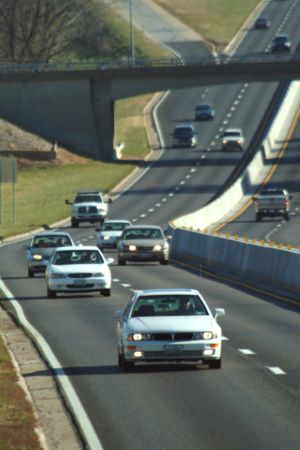
| − | The three types of median barrier used by MoDOT include concrete barrier, Type B [[606.1 Guardrail|guardrail]], and [[606.2 Guard Cable|guard cable]]. This article primarily deals with concrete barrier. There are many aspects to be considered when inspecting construction quality and this article also provides [[617.2 Construction Inspection Guidelines for Sec 617|construction inspection guidelines]]. | + | The three types of median barrier used by MoDOT include concrete barrier, Type B [[606.1 Guardrail|guardrail]], and [[606.2 Guard Cable|guard cable]]. This article primarily deals with concrete barrier. There are many aspects to be considered when inspecting construction quality and this article also provides [[617.2 Construction Inspection Guidelines for Sec 617|construction inspection guidelines]] as well as [[617.3 Material Inspection for Sec 617|material inspection guidelines]]. |
Concrete barrier and Type B guardrail are placed on a flush median. [[media:231_Warrant_for_Median_Barriers.pdf|Warrants for median barrier]] are used to determine the locations for which these two types of barrier are to be provided. Concrete barrier is generally limited to the high volume roadways with narrow width medians. When concrete barrier is used, Type C (and Type D, as required) is the preferred configuration for new construction. Type A (and Type B, as required) is only to be used for new construction projects in a retrofit condition or to “tie in” to existing Type A concrete barrier, which exists on adjoining sections of roadway. An approved crash cushion or sloped end crashworthy end terminal is the required end treatment for concrete barriers. A barrier height transition is not to be used in locations where the posted speed limit is greater than 35 mph. Where height transitions are used, they are to be located as far as practicable from the traffic lanes, and if possible, the lead end flared outside the clear zone. Concrete barrier details and barrier height transitions are shown in [http://www.modot.mo.gov/business/standards_and_specs/documents/61710.pdf Standard Plan 617.10]. The distance between the left hand edge of the lane next to the median and the face of the concrete median barrier is not to be more than 15 ft. (4.5 m). | Concrete barrier and Type B guardrail are placed on a flush median. [[media:231_Warrant_for_Median_Barriers.pdf|Warrants for median barrier]] are used to determine the locations for which these two types of barrier are to be provided. Concrete barrier is generally limited to the high volume roadways with narrow width medians. When concrete barrier is used, Type C (and Type D, as required) is the preferred configuration for new construction. Type A (and Type B, as required) is only to be used for new construction projects in a retrofit condition or to “tie in” to existing Type A concrete barrier, which exists on adjoining sections of roadway. An approved crash cushion or sloped end crashworthy end terminal is the required end treatment for concrete barriers. A barrier height transition is not to be used in locations where the posted speed limit is greater than 35 mph. Where height transitions are used, they are to be located as far as practicable from the traffic lanes, and if possible, the lead end flared outside the clear zone. Concrete barrier details and barrier height transitions are shown in [http://www.modot.mo.gov/business/standards_and_specs/documents/61710.pdf Standard Plan 617.10]. The distance between the left hand edge of the lane next to the median and the face of the concrete median barrier is not to be more than 15 ft. (4.5 m). | ||
Revision as of 11:14, 13 June 2007
| Key Points |
The three types of median barrier used by MoDOT include concrete barrier, Type B guardrail, and guard cable. This article primarily deals with concrete barrier. There are many aspects to be considered when inspecting construction quality and this article also provides construction inspection guidelines as well as material inspection guidelines.
Concrete barrier and Type B guardrail are placed on a flush median. Warrants for median barrier are used to determine the locations for which these two types of barrier are to be provided. Concrete barrier is generally limited to the high volume roadways with narrow width medians. When concrete barrier is used, Type C (and Type D, as required) is the preferred configuration for new construction. Type A (and Type B, as required) is only to be used for new construction projects in a retrofit condition or to “tie in” to existing Type A concrete barrier, which exists on adjoining sections of roadway. An approved crash cushion or sloped end crashworthy end terminal is the required end treatment for concrete barriers. A barrier height transition is not to be used in locations where the posted speed limit is greater than 35 mph. Where height transitions are used, they are to be located as far as practicable from the traffic lanes, and if possible, the lead end flared outside the clear zone. Concrete barrier details and barrier height transitions are shown in Standard Plan 617.10. The distance between the left hand edge of the lane next to the median and the face of the concrete median barrier is not to be more than 15 ft. (4.5 m).
| Figures |
| Warrant for Median Barriers |
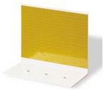
Permanent barrier wall and bridge barrier wall delineation shall be in accordance with Sec 617.30 of the Standard Specifications. The design of barrier wall delineators shall be in acordance with Standard Drawing 617.10 and Sec 1065.
Medians wider than 36 ft. (10.8 m) are sufficiently wide to satisfy clear zone requirements, thus making the provision of median barrier (refer to warrants for median barrier) optional. While the provision of a concrete barrier or Type B guardrail may not be required at these locations, a three-strand guard cable may be desirable.
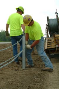
Although the cable system is relatively inexpensive to install, when compared with a concrete barrier or Type B guardrail system, and performs well when hit, it must be repaired after each hit to maintain its effectiveness. Especially for low-tension guard cable, this repair must be done as quickly as possible after a hit to ensure the effectiveness of the barrier. Consequently, its use in areas where it is likely to be frequently hit is not recommended. In these situations other types of median barrier are to be considered.
Guardrail or concrete barrier blunt ends located on either side of a two-way roadway or on the guardrail approach end of dual lane facilities must be replaced with an approved crashworthy end terminal even if the project covers only rehabilitation of the roadway in one direction.
617.1 Temporary Concrete Traffic Barrier
Temporary concrete traffic barrier prevents vehicles from entering the work area or to separate vehicles in temporary two-lane, two-way traffic on normally divided highways. The use of temporary concrete traffic barrier instead of standard temporary traffic control measures is based on engineering judgment. However, temporary concrete traffic barrier is required on bridge rehabilitation jobs with bridge rail replacement and/or full depth repair, and is to be considered for any other type of long-term bridge repair work. When specified, quantities are calculated and shown on the plans.
The preferred installation method for temporary concrete traffic barrier is freestanding and requires a minimum 2 ft. (0.6 m) buffer area behind the barrier to allow for lateral deflection in both work areas and lane separation situations. When freestanding installations are used on unprotected bridge decks, roadway excavation edge drop-offs and equipment and material storage locations, a 4 ft. (1.2 m) buffer area will be required. Concrete traffic barrier may be placed 6 in. (150 mm) from the edge of unprotected bridge decks if tie-down straps are used, however, a 3 ft. (0.9 m) buffer area must be maintained. On bridge decks where lateral deflection cannot be tolerated, the bolt through deck detail will be used. Standard Plan 617.20 illustrates the proper transition from freestanding barrier to barrier with anchor bolts on bridge decks. The method of installation on bridge decks will be determined by Bridge Division, and will be shown on the bridge plans. The above requirements shall be maintained when developing staging or phasing of work requiring temporary concrete traffic barrier. The lateral deflection limits are to be identified on the plans. No design exceptions will be allowed.
Pay items are available for Type F, Type F with Anchoring Systems and Type F with Tie-Down Strap, as well as pay items for relocating Type F, Type F with Anchoring Systems and Type F with Tie-Down Strap.
Appropriate channelizing devices and pavement marking are always used in front of barrier tapers for lane closures, shoulder closures or transition areas for temporary bypasses or connections as shown in the Engineering Policy Manual figures. Wherever practical, a lateral buffer space is to be provided between the edge of the driving lane and the barrier, and a longitudinal buffer space is to be provided between the channelizer taper and the barrier taper.
Contractors are not required to paint temporary concrete traffic barriers because delineators are used. Delineators for temporary concrete traffic barriers are provided at no direct pay as shown on Standard Plan 617.20 and stated in Standard Specification Sec 617. Delineator pay items are used only to retrofit existing permanent concrete traffic barrier.
617.1.1 Temporary Concrete Traffic Barrier End Treatments. Exposed temporary concrete traffic barrier ends are treated in one of the following methods (see Figure 616.1.2).
617.1.2 Barrier Flare. The barrier run is flared to the limits of the clear zone. The existing shoulder slope or median slope may be too steep for this type of installation. If this is the case, temporary grading is to be provided or other end treatments are to be used. The Roadside Design Guide contains recommended barrier placement in non-level medians. These guidelines also apply to outside shoulders.
617.1.3 Barrier Height Transition. A barrier height transition is designed to redirect traffic away from the blunt end of the barrier. A barrier height transition, as shown on Standard Plan 617.00, is installed on the exposed end of the barrier where the posted speed prior to construction on an existing facility or the anticipated posted speed of a temporary facility is 35 mph or less. When specified, quantities are calculated and shown on the plans.
617.1.4 Crash Cushion. Crash cushions are designed to absorb energy of an impacting vehicle and reduce the force on a passenger to an acceptable level. An approved crash cushion is installed on the exposed end of the barrier where the posted speed prior to construction on an existing facility or the anticipated posted speed of a temporary facility is greater than 35 mph. A crash cushion will be required on the upstream end for divided facilities, and on both ends for all two-way facilities. Crash cushions are discussed in 616.6, Lighting Devices. Applicable pay items are included in the plans. Special provisions are provided in the plans for non-standard devices. The types of crash cushions currently used are as follows:
- 617.1.4.1 Impact Attenuators (Sand Barrels). This system consists of a group of freestanding sand barrels and are discussed in 612 Impact Attenuators.
- 617.1.4.2 Proprietary Crash Cushions. These alternate crash cushions may be used when sufficient width is not available for sand barrels. These are typically used on the ends of temporary two-lane, two-way sections on divided highways. For temporary installations, typically acceptable Type C crash cushions are the Quadguard-CZ and the ADIEM II. For more information, refer to 606.1.3.2 Approved Crashworthy End Terminals.
617.1.5 Temporary Glare Screens. Temporary glare screens in work zones consist of modular units installed on top of temporary concrete traffic barrier. Temporary glare screens prevent headlight glare. Glare screens may also be used to block the driver’s view of construction activities. Glare screens are not used where they could restrict driver visibility and sight distance. Use of these units are limited due to installation and maintenance concerns to areas where work zone activities could impact the flow of traffic, or geometrics could create a blinding effect on drivers. When specified, quantities are calculated and shown on the plans.
Articles in "617 Traffic Barrier"
The following 5 pages are in this category, out of 5 total.
