Category:616 Temporary Traffic Control
Attention to the safety of travelers is especially important in work zones.
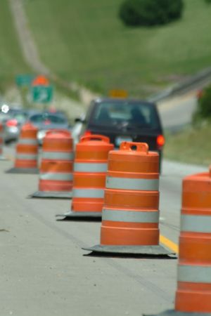
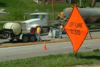
The work space is the area closed to traffic and set aside for workers, equipment and material. Work zone signing, items such as Type III Movable Barricades, channelizing devices, lighting devices and signals are specially designed to minimize risk to workers and travelers. Pavement edge treatment is frequently included in work zones as are practices such as bypasses, crossovers, temporary connections and detours.
To keep our work zones as safe as possible, Traffic Control for Field Operations contains information on temporary traffic control measures. Supervisors should use these guidelines with discretion since deviations may be necessary.
There are many aspects to be considered when inspecting construction quality and this article provides construction inspection guidelines.
Temporary traffic control devices warn motorists of hazards, advise the proper path through the work area,delineate areas where travelers may not operate and separate them from workers and opposing traffic. Whenever worn or damaged devices appear in a work zone, the general quality of the work zone deteriorates. To avoid this, MoDOT has provided quality standards for temporary traffic control devices.
To provide uniform flagging and to train employees how to protect themselves, co-workers and travelers, MoDOT requires flagger training.
Every day MoDOT has many work zones on Missouri's highways. MoDOT is committed to providing safe and efficient movement of both motorized and non-motorized traffic through or around temporary traffic control work zones and providing protection for workers and equipment located within these work zones. To better educate technicians and those designing and managing temporary traffic control work zones, Work Zone Technician Training and Advanced Work Zone Training is available.
This article also provides work zone signing applications, law enforcement services, temporary median crossovers for construction equipment, traffic control for non-motorized traffic and transit considerations.
Contents
616.1 Preparation of Traffic Control Plan (TCP)
This article outlines procedures for the preparation of traffic control plans, and supplements the MUTCD.
| Figures |
| Traffic Control Work Zone |
| Sign Spacing Device Spacing |
| Additional Information |
| MoDOT's Work Zone Web Map |
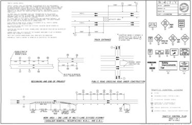
A Traffic Control Plan (TCP) is developed for every project. The TCP is an integral part of the planning and design of a project. The scope of the TCP is determined by the complexity of the project and is developed by the designer in the district in cooperation with district construction, maintenance and traffic personnel. Typical traffic control set-ups shall be shown for each work activity within the work zone. A preliminary field check with district construction and traffic is recommended to ensure the TCP will be compatible with field conditions.
In some cases, it may be necessary to obtain traffic count data from Transportation Planning to aid in the development of the TCP. This is especially the case where traffic capacity is a significant factor in the design of the TCP. Intersection traffic count data may also be requested from district traffic personnel. Hourly volumes can assist in determining the type of traffic control used, working hour restrictions and other aspects of the TCP. The use of Highway Capacity Software, VISSIM, CORSIM or other computer programs may aid in estimating queue lengths, delays, etc. resulting from the work zone.
When staged construction is used, the stages are to be clearly defined in the TCP. Each stage is to have a description of the type of work being done during that phase. Stationing is to be shown, if applicable.
Traffic control sheets must be provided in the traffic control plans showing the location of all traffic control devices.
On all interstate projects, or projects within interstate right of way (regardless of the funding type), the district shall submit a set of traffic control plans and associated JSPs to FHWA for review and approval. The district is to submit a complete set of traffic control plans and associated JSP’s to the Design Division, 14 weeks prior to the bid opening date (refer to 121, Project Prioritization and STIP Commitments). Upon approval, FHWA will send an approval letter to the district with a copy to the Design Division.
The designer is to become familiar with Standard Plans 612.20, 616.10, 617.10, 617.20 and 619.10 and Secs 612, 616, 617 and 619 of the Standard Specifications before preparing the traffic control plan.
Contractors are allowed to reuse traffic control devices from job to job, so designers are not to specify all devices on any particular job shall be new.
616.1.1 Typical Applications
The figures in this article include typical applications and examples of work zone traffic control. Since each project is unique, the figures cannot address every situation. The typical layouts are to be used as much as possible in developing the TCP, and may be adjusted to fit conditions using sound engineering judgment.
There are many items of work considered incidental. These incidental items are not to have a pay item included in the plans since their cost is included in the larger activity they are associated with.
616.1.2 Special Provisions
The “Work Zone Traffic Management Plan” special provision is required with all plans. This special provision can be modified to include job specific conditions. The purpose of this special provision is not to call the contractor's attention to the standard specifications or to reinforce the standard plans. Construction phases or stages are not to be included in this special provision. A job special provision is to be created by the district for any traffic control items not covered in the plans, standard plans or standard specifications, coordinated with the Design and Traffic Divisions.
616.1.3 Components of a Work Zone
The work zone is composed of four basic components: the advance warning area, transition area, activity area and buffer spaces.
616.1.3.1 Advance Warning Area. In the advance warning area, the drivers are informed of what to expect. The advance warning area contains warning signs with appropriate legends, regulatory signs, such as speed reduction signing, changeable message signs and other warning devices. The signs or other warning devices are positioned to give the driver sufficient time to react to the conditions. Warning devices are not to be placed too far in advance, as the warning message will lose effectiveness. Suggested advance sign spacing information is available.
In some cases on high volume routes, traffic backups due to the work activity may extend past the normal advance warning area. In this case, additional signing may be required to warn drivers before they reach the backup. For longer-term activities, alternate route signing and interactive devices or changeable message signs may be considered. Computer programs are available to aid in estimating back ups and delays due to work zones.
In some cases, particularly in urban areas, the advance warning area may extend through an intersection or interchange. Special considerations such as additional advance signs or adjustments to sign spacing may be needed to assure all approaching drivers are informed of the conditions.
616.1.3.2 Transition Area. When redirection of the driver's normal path is required, traffic must be channelized from the normal path to a new path. Transition areas usually involve strategic use of tapers, channelizing devices, signing, pavement marking and other traffic control devices.
There are three types of tapers: shoulder, lane and one-lane,two-way.
- The shoulder taper is used to close the shoulder where it is part of the activity area or when improved shoulders might be mistaken for a driving lane.
- The lane taper is used to close a driving lane by forcing traffic to merge.
Recommended taper length and channelizer spacing for shoulder and lane tapers in the transition area are shown in the following table.
Taper Spacing Chart
| Speed Limit, mph | Taper Length1, ft. | Channelizer Spacing4, ft. | |
|---|---|---|---|
| Shoulder2 (T1) | Lane3 (T2) | ||
| up to 35 | 70 | 245 | 355 |
| 40 to 45 | 150 | 540 | 405 |
| 50 to 55 | 185 | 660 | 506 |
| 60 to 70 | 235 | 840 | 606 |
| 1 Taper lengths may be adjusted to accommodate crossroads, curves, intersections, ramps or other geometric features. | |||
| 2 Based on 10 ft. shoulder width. | |||
| 3 Based on 12 ft. lane width | |||
| 4 Channelizer spacing may be reduced to discourage traffic encroachment. | |||
| 5 Spacing reduced to 1/2 at intersections. | |||
| 6 Spacing may be reduced to 1/2 at intersections. | |||
The one-lane, two-way taper is used to close one lane of a two-lane, undivided highway where the remaining lane is used alternately by traffic in each direction. The taper should have a length of 100 ft. (5 channelizers at 20 ft. spacing). In addition to the channelizers, a flagger, STOP or YIELD sign, pilot car or temporary traffic signal controls traffic through this section.
Taper lengths may be adjusted whenever they are located close to a crossroad, curve, intersection, ramp or other geometric feature.
Whenever tapers are used near interchange ramps, crossroads, curves or other influencing factors, it may be desirable to adjust the length of tapers. Longer tapers are not necessarily better than shorter tapers (particularly in urban areas characterized by short block lengths, driveways, etc.), because extended tapers may encourage motorists to delay lane changing. The real test of taper length involves observing motorists after the traffic control plan has been implemented.
616.1.3.3 Activity Area. The activity area is the area of the roadway where the work takes place. It is composed of the work space, traffic space and buffer space.
- The work space is the area closed to traffic and set aside for workers, equipment, materials and a protective vehicle, if one is used upstream. This area is usually delineated by channelizer or temporary barriers to exclude vehicles and pedestrians.
- The traffic space is the area in which traffic is routed through the activity area
The buffer space is discussed below, in 616.1.3.4.
When work occurs on a high-volume, highly congested facility in an urban area, incident management vehicle access to the work area shall be considered to allow quick response to traffic incidents with a minimum of interruption. This may involve providing storage space at the beginning or end of the activity area, or both. This storage space is not to extend into any portion of the buffer space.
616.1.3.4 Buffer Spaces. Buffer spaces provide a recovery space for an errant vehicle. Buffer spaces may be placed longitudinally or laterally with respect to the direction of traffic flow. Longitudinal buffer spaces are to be used whenever practicable. Lateral buffer spaces may be considered based on the type of work. Lateral buffer spaces are to be used when practicable between the traffic space and fixed objects or pavement drop-offs. Guidelines for the length of longitudinal buffer spaces are given below:
Recommended Length of Longitudinal Buffer Spaces
| POSTED SPEED PRIOR TO CONSTRUCTION, mph | LENGTH, ft. | LENGTH, m |
|---|---|---|
| up to 35 | 120 | 35 |
| 40 to 45 | 220 | 65 |
| 50 to 55 | 335 | 100 |
| 60 to 70 | 550 | 165 |
Articles in "616 Temporary Traffic Control"
The following 27 pages are in this category, out of 27 total.
6
- 616.1 General (MUTCD Chapter 6A)
- 616.2 Fundamental Principles (MUTCD Chapter 6B)
- 616.3 Temporary Traffic Control Elements (MUTCD Chapter 6C)
- 616.4 Pedestrian and Worker Safety (MUTCD Chapter 6D)
- 616.5 Flagger Control (MUTCD Chapter 6E)
- 616.6 Temporary Traffic Control Zone Devices (MUTCD 6F)
- 616.7 Type of Temporary Traffic Control Zone Activities (MUTCD 6G)
- 616.8 Typical Applications (MUTCD 6H)
- 616.9 Control of Traffic Through Traffic Incident Management Areas (MUTCD 6I)
- 616.10 Product Requirements for Temporary Traffic Control Devices, Pavement Marking and Delineation
- 616.11 Traffic Control for Waterways
- 616.12 Work Zone Speed Limits
- 616.13 Work Zone Capacity, Queue and Travel Delay
- 616.14 Work Zone Safety and Mobility Policy
- 616.15 Transit Considerations
- 616.16 Law Enforcement Services
- 616.17 Pavement Edge Treatment
- 616.18 Construction Inspection Guidelines for Sec 616
- 616.19 Quality Standards for Temporary Traffic Control Devices
- 616.20 Flagger Training
- 616.21 Work Zone Technician Training
- 616.22 Advanced Work Zone Training
- 616.23 Traffic Control for Field Operations
- 616.24 Traffic Control for Non-Motorized Traffic
- 616.25 MoDOT Work Zone Guidelines
- 616.26 Work Zone User Training
- 616.27 MoDOT Fleet Lighting


