Difference between revisions of "616.19 Quality Standards for Temporary Traffic Control Devices"
(updated per RR3853) |
|||
| (31 intermediate revisions by 4 users not shown) | |||
| Line 1: | Line 1: | ||
| − | + | <div style="float: right; margin-left: 30px; margin-bottom: 30px;">__TOC__</div> | |
| − | |||
| − | |||
| − | |||
| − | |||
| − | |||
| − | |||
| − | + | <div style="float: right; margin-left: 5px; width:300px; background-color: #f8f9fa; padding: 0.5em; border: 1px solid #a2a9b1; text-align:left;"> | |
| + | * [https://epg.modot.org/forms/general_files/TS/Work_Zone_Inspection_Checklist.pdf '''Temporary Traffic Control Inspection Worksheet'''] | ||
| + | ---- | ||
| + | *[https://epg.modot.org/forms/general_files/TS/Quality_Standards_for_Temporary_Traffic_Control_Devices_flyer.pdf '''Quality Standards for Temporary Traffic Control Devices'''] (This Work Zone flyer shows the top deficient Temporary Traffic Control Devices) | ||
| + | ---- | ||
| + | *[https://epg.modot.org/forms/general_files/TS/Quality_Standards_for_Temporary_Traffic_Control_Devices.pdf '''Easily Printable Version of Quality Standards for Temporary Traffic Control Devices'''] | ||
| + | </div> | ||
| − | + | Temporary traffic control devices (TTCDs) are an essential part of highway work zones. TTCDs warn motorists of hazards, advise them of the proper path through the work area, delineate areas where they may not operate and separate motorists from workers and opposing traffic. | |
| − | + | There are many factors that ensure the success of these functions; the placement and condition of each TTCD are two important factors. TTCDs that are worn, damaged or improperly installed will significantly lower the overall quality of a work zone. Clean, legible, properly installed TTCDs will command the respect of the traveling public. | |
| − | TTCDs | + | These quality standards are intended as a resource to determine if TTCDs are meeting current traffic needs in terms of legibility, visibility and other safety and mobility requirements for TTCDs (e.g., impact attenuators, truck-mounted attenuators, signs, channelizers, barricades, changeable message signs, flashing arrow panels, work zone traffic signals, temporary pavement marking, temporary traffic barrier, etc.) deployed on the state highway system. Effective application of these quality standards will benefit everyone that works in or navigates through work zones on the state highway system. |
| − | + | =616.19.1 Quality Requirements= | |
| + | TTCDs shall be installed and maintained in an acceptable condition. Unless specified otherwise, this requirement does not mandate the use of new devices, but it does necessitate the use of functional devices. Unacceptable devices shall be replaced or corrected in accordance with the contract documents or in the absence of a contract (e.g., permit projects) as directed by MoDOT’s representative. | ||
| − | + | When reviewing work zones, the MoDOT Work Zone Inspection Checklist is a valuable tool for determining the safety and mobility performance of all work zones including federal and state funded contracts, state maintenance, and permit projects. | |
| − | + | Document all deficiencies on the checklist along with any corrective action(s) taken and/or the time/date that appropriate personnel was contacted to initiate the corrective action(s). | |
| − | |||
| − | |||
| − | |||
| − | |||
| − | |||
| − | |||
| − | |||
| − | |||
| − | |||
| − | |||
| − | |||
| − | |||
| − | |||
| − | |||
| − | |||
| − | Document all deficiencies on the | ||
The work zone should be re-inspected to ensure that all deficiencies have been corrected. | The work zone should be re-inspected to ensure that all deficiencies have been corrected. | ||
| − | + | =616.19.2 Quality Standards= | |
| − | |||
| − | |||
| − | |||
| − | |||
| − | |||
| − | |||
| − | |||
| − | |||
| − | |||
| − | |||
| − | |||
| − | |||
| − | |||
| − | |||
| − | |||
| − | |||
| − | |||
| − | |||
| − | |||
| − | |||
| − | |||
| − | |||
| − | |||
| − | |||
| − | |||
| − | |||
| − | |||
| − | |||
| − | |||
| − | |||
| − | |||
| − | |||
| − | |||
| − | |||
| − | + | ==616.19.2.1 [[616.6_Temporary_Traffic_Control_Zone_Devices_%28MUTCD_6F%29#616.6.1_Types_of_Devices_.28MUTCD_6F.01.29|General]]== | |
| − | |||
| − | |||
| + | All TTCDs shall be: | ||
| + | :* In conformance with the requirements of the MUTCD and MoDOT Standards. | ||
| + | :* Installed and maintained at locations and in orientations that maximize safety and minimize disruption to traffic flow. Aligned with the road user’s line of sight. | ||
| + | :* Positioned in a manner not to obstruct other traffic control devices. | ||
| + | :* Free of dents, holes, deformations, abrasions, tears, marks, stains, residues, fading or other deficiencies that adversely affects the operational performance including the crashworthiness of a device. | ||
| + | :* Properly covered, turned, stowed, or removed when not in use. Visible during daytime and nighttime operations. | ||
| − | + | If TTCDs such as signs, channelizers, etc. have damage resulting in 25% or more deterioration of the lettering, border, or symbol, the device shall be replaced in an agreed upon time with the engineer. Furthermore, if the device is experiencing a reduction in retroreflectivity by 25% or more due to residue, fading, or damage, the device shall be replaced in an agreed upon time with the engineer. | |
| − | ====616.19.2.2. | + | ==616.19.2.2 Advance Warning Area== |
| + | ===616.19.2.2.1 [[616.6_Temporary_Traffic_Control_Zone_Devices_%28MUTCD_6F%29#616.6.3_Sign_Placement_.28MUTCD_6F.03.29|Sign Placement and Installation]]=== | ||
| − | + | <gallery widths=250px heights=250px position="right" style="text-align:center; font-weight:bold; margin-left:0em" caption="Acceptable Examples"> | |
| − | + | File:616.19.2.2.1_01.jpg|(1) | |
| − | + | File:616.19.2.2.1_02.jpg|(2) | |
| + | File:616.19.2.2.1_03.jpg|(3) | ||
| + | </gallery> | ||
| + | The post mounted sign shown in '''Picture 1''' is mounted 5-foot in height from the edge of the roadway to the bottom of the sign as required for a rural location. For urban locations, post mounted signs shall be 7-feet as shown in '''Picture 2'''. For short term projects temporary signs, as shown in '''Picture 3''', may have a minimum height of one foot. For additional information on sign installation and heights see [https://www.modot.org/standard-plans-section-600 Standard (Std.) Plan 616.10]]. | ||
| − | + | <gallery widths=250px heights=250px position="right" style="text-align:center; font-weight:bold; margin-left:0em" caption="Acceptable Examples"> | |
| − | + | File:616.19.2.2.1_04.jpg|(4) | |
| − | + | </gallery> | |
| − | + | When used, speed limit (regulatory) signs shall be installed at a 5-foot (rural area) or a 7-foot (urban area) mounting height as shown in '''Picture 4'''. Information on the mounting height of the signs is in [https://www.modot.org/standard-plans-section-600 Std. Plan 616.10]. The WORK ZONE PLAQUE (Go20-5Ap) shall be 2-foot height as shown in [[616.6_Temporary_Traffic_Control_Zone_Devices_(MUTCD_6F)#616.6.12_Work_Zone_and_Higher_Fines_Signs_and_Plaques_.28MUTCD_6F.12.29|EPG 616.6.12 Work Zone and Higher Fines Signs and Plaques (MUTCD 6F12)]]. | |
| − | |||
| − | |||
| − | |||
| − | |||
| − | === | + | <gallery widths=250px heights=250px position="right" style="text-align:center; font-weight:bold; margin-left:0em" caption="Unacceptable Examples"> |
| − | + | File:616.19.2.2.1_05.jpg|(5) | |
| − | + | </gallery> | |
| − | + | The mounting height and the WORK ZONE plaque (GO20-5aP) of the sign in '''Pictures 5''' is not compliant with MoDOT/MUTCD standards. | |
| − | |||
| − | |||
| − | |||
| − | |||
| − | |||
| − | + | '''Lateral Sign Location:''' Sign locations shall be located 6-12 feet from the edge of the paved travel lane or shoulder as shown in [https://www.modot.org/standard-plans-section-600 Std. Plan 616.10]. Before installing signs, the project site should be reviewed to agree on the best location for signs. When stubs are not driven deep enough into the ground a sign may lean or fall after a period of time. Due to terrain slopes, curves, shoulder widths, duration of projects, signs may deviate from recommended placement to achieve a plumb position, be sure to document. | |
| − | |||
| − | |||
| − | |||
| − | |||
| − | |||
| − | |||
| − | |||
| − | |||
| − | |||
| − | |||
| − | |||
| − | |||
| − | |||
| − | |||
| − | |||
| − | |||
| − | |||
| − | |||
| − | |||
| − | |||
| − | |||
| − | |||
| − | |||
| − | |||
| − | |||
| − | |||
| − | |||
| − | |||
| − | |||
| − | |||
| − | |||
| − | |||
| − | |||
| − | |||
| − | |||
| − | |||
| − | |||
| − | |||
| − | |||
| − | |||
| − | |||
| − | |||
| − | |||
| − | |||
| − | |||
| − | |||
| − | |||
'''Post Installations:''' | '''Post Installations:''' | ||
| − | + | <gallery widths=250px heights=250px position="right" style="text-align:center; font-weight:bold; margin-left:0em" caption="Acceptable Examples"> | |
| − | + | File:616.19.2.2.1_06.jpg|(6) | |
| − | + | </gallery> | |
| − | + | '''Picture 6''' illustrates the proper installation for posts. The complete U-channel Post details are located in [https://www.modot.org/standard-plans-section-600 Std. Plan 616.10]. | |
| − | |||
| − | |||
| − | |||
| − | |||
| − | |||
| − | |||
| − | |||
| − | |||
| − | |||
| − | |||
| − | |||
| − | |||
| − | |||
| − | |||
| − | |||
| − | |||
| − | |||
| − | |||
| − | |||
| − | |||
| − | |||
| − | |||
| − | |||
| − | |||
| − | |||
| − | |||
| − | |||
| − | |||
| − | |||
| − | |||
| − | |||
| − | |||
| − | |||
| − | |||
| − | |||
| − | |||
| − | |||
| − | |||
| − | |||
| − | |||
| − | |||
| − | |||
| − | |||
| − | |||
| − | |||
| − | |||
| − | |||
| − | |||
| − | |||
| − | |||
| − | |||
| − | |||
| − | |||
| − | |||
| − | |||
| − | |||
| − | |||
| − | |||
| − | |||
| − | |||
| − | |||
| − | |||
| − | |||
| − | |||
| − | |||
| − | |||
| − | + | <gallery widths=250px heights=250px position="right" style="text-align:center; font-weight:bold; margin-left:0em" caption="Acceptable Examples"> | |
| + | File:616.19.2.2.1_07.jpg|(7) | ||
| + | </gallery> | ||
| + | '''Picture 7''' is an example of a correct U-channel post splice, which shows the four bolts in the proper location, correct stub height and splice overlap.</br> | ||
| + | ::Note: The bolts can be installed in either direction.</br> | ||
| + | ::Note: Missouri One-Call shall always be notified prior to installing any signpost into the ground. | ||
| − | ===616.19.2. | + | <gallery widths=250px heights=250px position="right" style="text-align:center; font-weight:bold; margin-left:0em" caption="Unacceptable Examples"> |
| + | File:616.19.2.2.1_08.jpg|(8) | ||
| + | File:616.19.2.2.1_09.jpg|(9) | ||
| + | </gallery> | ||
| + | The stub height and splice overlap in '''Picture 8''' is correct, but the 4-bolts are not in the proper locations. '''Picture 9''' shows inadequate stub height and overlap and the signpost is not on the correct side of the stub. | ||
| − | + | <gallery widths=250px heights=250px position="right" style="text-align:center; font-weight:bold; margin-left:0em" caption="Unacceptable Examples"> | |
| − | + | File:616.19.2.2.1_10.jpg|(10) | |
| − | Picture | + | File:616.19.2.2.1_11.jpg|(11) |
| + | File:616.19.2.2.1_12.jpg|(12) | ||
| + | </gallery> | ||
| + | The installations in '''Pictures 10-12''' are unacceptable. '''Picture 10''' shows an installation of only 1 bolt per signpost leg. '''Picture 11''' shows an installation of one post mounted leg and one skid mounted leg. '''Picture 12''' shows two splices when only one splice is allowed. | ||
| − | + | <gallery widths=250px heights=250px position="right" style="text-align:center; font-weight:bold; margin-left:0em" caption="Acceptable Examples"> | |
| − | + | File:616.19.2.2.1_13.jpg|(13) | |
| − | + | </gallery> | |
| − | + | '''Picture 13''' is a Perforated Square Steel Tube Post (PSST) with more details located in [https://www.modot.org/standard-plans-section-600 Std. Plan 616.10]. | |
| − | |||
| − | + | <gallery widths=250px heights=250px position="right" style="text-align:center; font-weight:bold; margin-left:0em" caption="Acceptable Examples"> | |
| + | File:616.19.2.2.1_14.jpg|(14) | ||
| + | File:616.19.2.2.1_15.jpg|(15) | ||
| + | </gallery> | ||
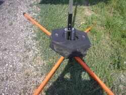
| + | '''Pictures 14 and 15''' show proper installation of a PSST post. The PSST post does not have to use the corner bolt but can be bolted either with one or two straight bolts. However, the corner bolt minimizes movement of the post within the tubes. | ||
| + | ::Note: Missouri One-Call shall always be notified prior to installing any signpost into the ground. | ||
| − | + | <gallery widths=250px heights=250px position="right" style="text-align:center; font-weight:bold; margin-left:0em" caption="Unacceptable Examples"> | |
| − | + | File:616.19.2.2.1_16.jpg|(16) | |
| − | + | </gallery> | |
| + | '''Picture 16''' shows a stub higher than the 2-inches maximum and the bolt should be bolted through the two posts. | ||
| − | + | ===616.19.2.2.2 [[616.6_Temporary_Traffic_Control_Zone_Devices_%28MUTCD_6F%29#616.6.17_Position_of_Advance_Warning_Signs_.28MUTCD_6F.17.29|Sign]], [[616.6_Temporary_Traffic_Control_Zone_Devices_%28MUTCD_6F%29#616.6.2.2_Flags_and_Advance_Warning_Rail_System_on_Signs|Flag and AWRS Quality]]=== | |
| − | + | <gallery widths=250px heights=250px position="right" style="text-align:center; font-weight:bold; margin-left:0em" caption="Acceptable Examples"> | |
| − | + | File:616.19.2.2.2_01.jpg|(1) | |
| − | + | File:616.19.2.2.2_02.jpg|(2) | |
| − | + | File:616.19.2.2.2_03.jpg|(3) | |
| − | + | </gallery> | |
| − | + | The signs in '''Pictures 1, 2 and 3''' are considered in good quality. Supplemental devices such as flags and/or a cone may be placed next to a sign. Picture 2 is an example of the proper placement of a FLAGGER (WO20-7) sign, with the optional flags, in advance of the hill versus after the hill. In urban areas with barrier walls and narrow shoulders, a truncated sign may be used as shown in Picture 3. | |
| − | |||
| − | + | ::Note: TTCDs may be highly visible during the day but may not be at night due to inadequate retroreflectivity. MoDOT and Contractor representatives should drive through the work zone at night to check nighttime visibility. | |
| − | |||
| − | |||
| − | + | <gallery widths=250px heights=250px position="right" style="text-align:center; font-weight:bold; margin-left:0em" caption="Unacceptable Examples"> | |
| − | + | File:616.19.2.2.2_04.jpg|(4) | |
| − | + | File:616.19.2.2.2_05.jpg|(5) | |
| + | File:616.19.2.2.2_06.jpg|(6) | ||
| + | File:616.19.2.2.2_07.jpg|(7) | ||
| + | File:616.19.2.2.2_08.jpg|(8) | ||
| + | File:616.19.2.2.2_09.jpg|(9) | ||
| + | </gallery> | ||
| + | '''Pictures 4-7''' are in unacceptable condition. Dirty or damaged signs should be cleaned, repaired, or replaced before being installed. When cleaning, follow manufacturer’s recommendations, so the daytime and nighttime visibility of the sign is not adversely impacted. The MEN WORKING sign ('''Picture 8''') should be replaced with worker symbol sign or WORKERS sign (WO-21-1 or 1a) to meet current standards. '''Picture 9''' shows unacceptable flags, if used, deteriorated flags should be replaced. | ||
| − | ===616.19.2. | + | <gallery widths=250px heights=250px position="right" style="text-align:center; font-weight:bold; margin-left:0em" caption="Unacceptable Examples"> |
| + | File:616.19.2.2.2_10.jpg|(10) | ||
| + | File:616.19.2.2.2_11.jpg|(11) | ||
| + | File:616.19.2.2.2_12.jpg|(12) | ||
| + | File:616.19.2.2.2_13.jpg|(13) | ||
| + | </gallery> | ||
| + | '''Pictures 10 - 13''' are examples of unacceptable nighttime visibility. Proper storing, transporting, and covering signs is crucial to minimizing deficiencies. | ||
| − | + | <gallery widths=250px heights=250px position="right" style="text-align:center; font-weight:bold; margin-left:0em" caption="Acceptable Examples"> | |
| − | + | File:616.19.2.2.2_14.jpg|(14) | |
| − | + | File:616.19.2.2.2_15.jpg|(15) | |
| + | File:616.19.2.2.2_16.jpg|(16) | ||
| + | </gallery> | ||
| + | Advance Warning Rail System (AWRS) shall be installed on the first advance warning sign (Road/Bridge Work Ahead) on long-term stationary projects. The barricade stripes shall slope downward toward the roadway as shown above. '''Picture 14''' is an example of acceptable AWRS installations. When a Type 3 Barricade is used with a sign as shown '''Picture 15''', the barricade shall be located between 7 to 10 feet from the sign (to be crashworthy). Either a 4-foot or 8-foot barricade may be used. A 4 foot AWRS on single post is acceptable as shown in '''Picture 16''' provided the signpost has been sized to accommodate the added weight and square footage of the AWRS. | ||
| − | + | ===616.19.2.2.3 [[616.6_Temporary_Traffic_Control_Zone_Devices_%28MUTCD_6F%29#616.6.16_Warning_Sign_Function.2C_Design_and_Application_.28MUTCD_6F.16.29|Proper Sign Color]]=== | |
| − | + | Sign colors are reserved for specific applications. Orange is reserved for temporary traffic control, pink for incident management, yellow for warning, and red/black/white for regulatory signs. | |
| + | <gallery widths=250px heights=250px position="right" style="text-align:center; font-weight:bold; margin-left:0em" caption="Acceptable Examples"> | ||
| + | File:616.19.2.2.3_01.jpg|(1) | ||
| + | </gallery> | ||
| + | Fluorescent orange signs as shown on the right in '''Picture 1''' are required for MoDOT contract and maintenance projects. Permit projects may use engineering grade sheeting as shown on the left side of '''Picture 1''' provided they meet MUTCD reflectivity requirements. | ||
| − | + | <gallery widths=250px heights=250px position="right" style="text-align:center; font-weight:bold; margin-left:0em" caption="Unacceptable Examples"> | |
| − | + | File:616.19.2.2.3_01.jpg|(2) | |
| − | + | File:616.19.2.2.3_02.jpg|(3) | |
| + | </gallery> | ||
| + | The UTILITY WORK AHEAD (WO21-7) and the LANE CLOSED AHEAD (WO20-5) signs in '''Pictures 2 and 3''' should be orange not pink or yellow. Note: Using tape on a sign can destroy the retroreflectivity of the sign as shown in '''Picture 3'''. | ||
| − | [[ | + | ===616.19.2.2.4 [[616.6_Temporary_Traffic_Control_Zone_Devices_%28MUTCD_6F%29#616.6.17_Position_of_Advance_Warning_Signs_.28MUTCD_6F.17.29|Information From the Signs]]=== |
| − | + | <gallery widths=250px heights=250px position="right" style="text-align:center; font-weight:bold; margin-left:0em" caption="Unacceptable Examples"> | |
| − | + | File:616.19.2.2.4_01.jpg|(1) | |
| + | File:616.19.2.2.4_02.jpg|(2) | ||
| + | File:616.19.2.2.4_03.jpg|(3) | ||
| + | </gallery> | ||
| + | '''Pictures 1 - 3''' are examples of signs that are visually obstructed or providing conflicting information. '''Picture 1''' should be moved upstream from the permanent curve warning sign with written documentation as to why the sign was moved. The advance warning sign in '''Picture 2''' should be relocated upstream of the tree or the tree should be trimmed (if within MoDOT ROW) to provide the required visibility. '''Picture 3''' shows detour signs that are providing two detour options for the same route. To reduce road user confusion, it is best to provide only one detour option. | ||
| − | + | <gallery widths=250px heights=250px position="right" style="text-align:center; font-weight:bold; margin-left:0em" caption="Acceptable Examples"> | |
| − | + | File:616.19.2.2.4_04.jpg|(4) | |
| − | + | </gallery> | |
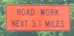
| − | + | '''Picture 4''' is an acceptable use of the ROAD WORK NEXT XX MILES (GO20-1), as it uses whole numbers only. Do not use decimals of a mile. | |
| − | |||
| − | |||
| − | |||
| − | |||
| − | |||
| − | |||
| − | |||
| − | |||
| − | |||
| − | ===616.19.2. | + | <gallery widths=250px heights=250px position="right" style="text-align:center; font-weight:bold; margin-left:0em" caption="Unacceptable Examples"> |
| + | File:616.19.2.2.4_05.jpg|(5) | ||
| + | File:616.19.2.2.4_06.jpg|(6) | ||
| + | </gallery> | ||
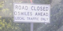
| + | '''Pictures 5 and 6''' are unacceptable signs because the specified miles are not listed as whole numbers. | ||
| − | + | ===616.19.2.2.5 Ballasting of Signs=== | |
| + | <gallery widths=250px heights=250px position="right" style="text-align:center; font-weight:bold; margin-left:0em" caption="Acceptable Examples"> | ||
| + | File:616.19.2.2.5_01.jpg|(1) | ||
| + | </gallery> | ||
| + | For portable signs, ballasting should be limited to one sandbag layer on the sign legs as shown in '''Picture 1'''. | ||
| − | + | <gallery widths=250px heights=250px position="right" style="text-align:center; font-weight:bold; margin-left:0em" caption="Unacceptable Examples"> | |
| + | File:616.19.2.2.5_02.jpg|(2) | ||
| + | File:616.19.2.2.5_03.jpg|(3) | ||
| + | </gallery> | ||
| + | The use of channelizer rings as shown in '''Pictures 2 and 3''' are unacceptable as the crashworthiness has not been verified. | ||
| − | + | <gallery widths=250px heights=250px position="right" style="text-align:center; font-weight:bold; margin-left:0em" caption="Acceptable Examples"> | |
| − | + | File:616.19.2.2.5_04.jpg|(4) | |
| + | File:616.19.2.2.5_05.jpg|(5) | ||
| + | </gallery> | ||
| + | For skid mounted signs, ballasting should be limited to one sandbag layer on the sign legs as shown in '''Pictures 4 and 5'''. '''Picture 5''' shows an acceptable use of ballasting for a skid mounted sign. The crossbar ('''Picture 5''') should be no higher than 12 inches (one sandbag over the crossbar is acceptable). | ||
| − | + | <gallery widths=250px heights=250px position="right" style="text-align:center; font-weight:bold; margin-left:0em" caption="Unacceptable Examples"> | |
| − | | | + | File:616.19.2.2.5_06.jpg|(6) |
| − | + | File:616.19.2.2.5_07.jpg|(7) | |
| − | + | File:616.19.2.2.5_08.jpg|(8) | |
| − | + | </gallery> | |
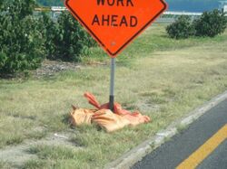
| − | + | '''Picture 6''' shows a large mound of sandbags, which if hit could present a ramping situation for vehicles. '''Picture 7''' has two sandbags on the crossbar which is unacceptable and utilizes two types of mounting styles. In '''Picture 8''', concrete is being used to ballast the sign, which is not crashworthy and is unacceptable. | |
| − | |||
| − | |||
| − | + | ===616.19.2.2.6 Additional Sign Examples=== | |
| − | | | + | <gallery widths=250px heights=250px position="right" style="text-align:center; font-weight:bold; margin-left:0em" caption="Unacceptable Examples"> |
| − | | | + | File:616.19.2.2.6_01.jpg|(1) |
| − | + | File:616.19.2.2.6_02.jpg|(2) | |
| − | + | File:616.19.2.2.6_03.jpg|(3) | |
| − | + | File:616.19.2.2.6_04.jpg|(4) | |
| − | + | </gallery> | |
| − | + | '''Picture 1''' shows a crossbar above the 18-inch maximum height without sandbag or 12-inch maximum height with sandbag. '''Picture 2''' shows a skid mounted sign stand laying on the ground attached to the sign post. The skid mount should be removed from the sign post and placed flat on the ground. As shown, this sign stand is not crashworthy. '''Picture 3''' shows a sign laying in the street. This sign should be placed in a better location. '''Picture 4''' shows two crashworthy signs that have been placed closer than the recommended 7-10 feet spacing making them not crashworthy. The 7-10 feet spacing allows the signs to act independently of each other to meet crashworthy criteria. | |
| − | + | <gallery widths=250px heights=250px position="right" style="text-align:center; font-weight:bold; margin-left:0em" caption="Unacceptable Examples"> | |
| − | + | File:616.19.2.2.6_05.jpg|(5) | |
| − | + | File:616.19.2.2.6_06.jpg|(6) | |
| + | File:616.19.2.2.6_07.jpg|(7) | ||
| + | </gallery> | ||
| + | '''Picture 5''' is an example of a STOP (R1-1) sign not having a full face visible to the road user. The sign in '''Picture 6''' is leaning and should be plumb. The sign in '''Picture 7''' could be moved upstream or downstream to achieve a plumb position. Be sure to document the location change, such as, “After reviewing the sign in the original position, the sign was moved 100-feet upstream to be achieve a plumb position”. | ||
| − | ===616.19.2. | + | <gallery widths=250px heights=250px position="right" style="text-align:center; font-weight:bold; margin-left:0em" caption="Unacceptable Examples"> |
| + | File:616.19.2.2.6_08.jpg|(8) | ||
| + | File:616.19.2.2.6_09.jpg|(9) | ||
| + | File:616.19.2.2.6_10.jpg|(10) | ||
| + | </gallery> | ||
| + | Sign placement in urban areas can impede non-motorized travel as shown in '''Picture 8'''. Accommodations should be made for all modes of travel including non-motorized traffic such as, pedestrians and bicyclists. The signpost in '''Picture 9''' should have only one sign. A permanently posted SPEED LIMIT (R2-1) sign, as shown in '''Picture 10''', should not be removed. If the posted speed limit is lowered, the proper procedure is to cover the sign as described in [[616.19_Quality_Standards_for_Temporary_Traffic_Control_Devices#616.19.2.2.7_Sign_Coverings|616.19.2.2.7 Sign Coverings]]. | ||
| − | + | <gallery widths=250px heights=250px position="right" style="text-align:center; font-weight:bold; margin-left:0em" caption="Unacceptable Examples"> | |
| + | File:616.19.2.2.6_11.jpg|(11) | ||
| + | File:616.19.2.2.6_12.jpg|(12) | ||
| + | </gallery> | ||
| + | '''Picture 11''' shows an example of two work zones placed inside each other. Proper coordination should be one of the highest considerations when work zones overlap each other. '''Picture 12''' shows the signal head upside down. | ||
| − | + | ===616.19.2.2.7 Sign Coverings=== | |
| − | + | <gallery widths=250px heights=250px position="right" style="text-align:center; font-weight:bold; margin-left:0em" caption="Acceptable Examples"> | |
| + | File:616.19.2.2.7_01.jpg|(1) | ||
| + | File:616.19.2.2.7_02.jpg|(2) | ||
| + | File:616.19.2.2.7_03.jpg|(3) | ||
| + | </gallery> | ||
| + | '''Pictures 1 - 3''' show examples of signs properly covered with plastic sign cover, plastic taped securely to the sign without direct contact with the sign face and a roll-up sign folded down. Materials used should not allow the sign face to “bleed through” during daytime or nighttime use. '''Pictures 1 and 2''' adequately cover the face of the sign. | ||
| − | + | <gallery widths=250px heights=250px position="right" style="text-align:center; font-weight:bold; margin-left:0em" caption="Acceptable Examples"> | |
| − | + | File:616.19.2.2.7_04.jpg|(4) | |
| − | + | File:616.19.2.2.7_05.jpg|(5) | |
| + | File:616.19.2.2.7_06.jpg|(6) | ||
| + | </gallery> | ||
| + | '''Pictures 4 - 6''' are examples of acceptable materials to cover signs. Materials range from rubber that is used for mud flaps or a matching sized sign cover. The sign covers should be adequately secured to the host sign assembly and sized to match the sign to completely cover the face. The cover should be constructed with non-metallic (such as wooden, plastic, etc.) handles and spacers to keep the sign covers from damaging the sign face. | ||
| − | : | + | <gallery widths=250px heights=250px position="right" style="text-align:center; font-weight:bold; margin-left:0em" caption="Unacceptable Examples"> |
| − | + | File:616.19.2.2.7_07.jpg|(7) | |
| + | File:616.19.2.2.7_08.jpg|(8) | ||
| + | File:616.19.2.2.7_09.jpg|(9) | ||
| + | File:616.19.2.2.7_10.jpg|(10) | ||
| + | </gallery> | ||
| + | The sign cover in '''Picture 7''' is not securely fastened and does not have a non-metallic handle. '''Picture 8''' shows the sign cover not matching the shape of the host sign, which could provide conflicting information to the road user. '''Picture 9''' shows duct tape covering part of the sign wording, which can damage the sign retroreflectivity. '''Picture 10''' shows an example of unacceptable use of plastic taped to the sign. The plastic is thin which illustrates the “bleed through” of the message and it is falling off and the sign. | ||
| − | [[ | + | ===616.19.2.2.8 [[616.6_Temporary_Traffic_Control_Zone_Devices_%28MUTCD_6F%29#616.6.68_Type_1_or_3_Barricades_.28MUTCD_6F.68.29|Barricades]]=== |
| − | + | <gallery widths=250px heights=250px position="right" style="text-align:center; font-weight:bold; margin-left:0em" caption="Acceptable Examples"> | |
| − | + | File:616.19.2.2.8_01.jpg|(1) | |
| + | File:616.19.2.2.8_02.jpg|(2) | ||
| + | </gallery> | ||
| + | '''Picture 1''' shows the proper placement of Type 3 barricades on a full roadway closure, including stripe direction. The barricade installation also provides an adequate buffer space to the work area. At some locations, barricades may have to be located at the bridge ends or work area due to side roads. '''Picture 2''' shows equipment behind the barricades. | ||
| − | + | <gallery widths=250px heights=250px position="right" style="text-align:center; font-weight:bold; margin-left:0em" caption="Unacceptable Examples"> | |
| + | File:616.19.2.2.8_03.jpg|(3) | ||
| + | File:616.19.2.2.8_04.jpg|(4) | ||
| + | </gallery> | ||
| + | '''Picture 3''' shows a barricade installation located after the private entrance and before the bridge end, not leaving enough buffer space. In '''Picture 4''', notice the left barricade stripes are angling to the left instead of to the right. | ||
| − | + | <gallery widths=250px heights=250px position="right" style="text-align:center; font-weight:bold; margin-left:0em" caption="Unacceptable Examples"> | |
| + | File:616.19.2.2.8_05.jpg|(5) | ||
| + | File:616.19.2.2.8_06.jpg|(6) | ||
| + | File:616.19.2.2.8_07.jpg|(7) | ||
| + | </gallery> | ||
| + | '''Picture 5''' shows Type 3 barricades that were moved to let vehicles into the work zone. '''Picture 6''' shows a haul truck entering a work zone and leaving the barricades open which could allow the road user to follow the haul truck. '''Picture 7''' shows the barricades staggered to allow haul trucks in and out of the work zone which is not permitted. | ||
| − | Pictures | + | <gallery widths=250px heights=250px position="right" style="text-align:center; font-weight:bold; margin-left:0em" caption="Unacceptable Examples"> |
| + | File:616.19.2.2.8_08.jpg|(8) | ||
| + | File:616.19.2.2.8_09.jpg|(9) | ||
| + | </gallery> | ||
| + | '''Pictures 8 and 9''' show trucks parked in front of barricades, obstructing them from oncoming traffic. Note: Equipment or vehicles should not be parked in front of barricades they should be moved to an appropriate location (i.e., behind the barricades). | ||
| − | + | <gallery widths=250px heights=250px position="right" style="text-align:center; font-weight:bold; margin-left:0em" caption="Acceptable Examples"> | |
| − | + | File:616.19.2.2.8_10.jpg|(10) | |
| − | + | File:616.19.2.2.8_11.jpg|(11) | |
| + | </gallery> | ||
| + | '''Picture 10''' shows a soft closure which is intended to allow local traffic only to get to the desired destination before the full closure. One barricade and ROAD CLOSED (R11-2) sign as shown in '''Picture 11''' can be used to inform the road user of closures, which when used should be located on the shoulder. | ||
| − | + | <gallery widths=250px heights=250px position="right" style="text-align:center; font-weight:bold; margin-left:0em" caption="Unacceptable Examples"> | |
| − | + | File:616.19.2.2.8_12.jpg|(12) | |
| − | Picture | + | </gallery> |
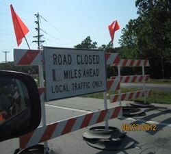
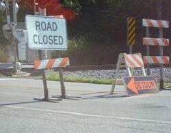
| + | The barricade in '''Picture 12''' is directing the road user into the opposite lane and not directing them back into the proper lane of travel with another barricade in the opposite lane. A single “ROAD CLOSED XX MILES AHEAD” (R11-3a) sign is allowed without barricades. Note: A full barricade closure is required at the work area. | ||
| − | + | <gallery widths=250px heights=250px position="right" style="text-align:center; font-weight:bold; margin-left:0em" caption="Unacceptable Examples"> | |
| − | + | File:616.19.2.2.8_13.jpg|(13) | |
| − | + | File:616.19.2.2.8_14.jpg|(14) | |
| − | + | File:616.19.2.2.8_15.jpg|(15) | |
| − | + | File:616.19.2.2.8_16.jpg|(16) | |
| + | </gallery> | ||
| + | The ballasting in '''Pictures 13 - 16''' show unacceptable applications. Tires should not be used as ballast. Sandbags are allowed if they are not stacked on each other (i.e.,a single layer to meet crashworthiness). As shown in Pictures '''13 - 15''', the signs may be placed behind the Type 3 barricades. To be crashworthy, the sign and barricade should be separated by 7 to 10 feet from each other so each device can act independently if struck by a vehicle. '''Picture 16''' shows old barrel rings around the legs of the barricades. If rings are used, only one is allowed per leg. | ||
| − | + | <gallery widths=250px heights=250px position="right" style="text-align:center; font-weight:bold; margin-left:0em" caption="Unacceptable Examples"> | |
| + | File:616.19.2.2.8_17.jpg|(17) | ||
| + | File:616.19.2.2.8_18.jpg|(18) | ||
| + | File:616.19.2.2.8_19.jpg|(19) | ||
| + | </gallery> | ||
| + | The road closures in '''Pictures 17 -19''' are unacceptable installations, the Type 3 barricades should cover the full roadway width to meet the requirements for a full road closure. The damaged rail sheeting on the barricades in '''Picture 19''' is unacceptable. | ||
| − | + | ===616.19.2.2.9 [[616.6_Temporary_Traffic_Control_Zone_Devices_%28MUTCD_6F%29#616.6.60_Portable_Changeable_Message_Signs_.28MUTCD_6F.60.29|Changeable Message Sign]] / [[616.6_Temporary_Traffic_Control_Zone_Devices_%28MUTCD_6F%29#616.6.61_Arrow_Boards_.28MUTCD_6F.61.29|Flashing Arrow Panels]] / [[616.6_Temporary_Traffic_Control_Zone_Devices_%28MUTCD_6F%29#616.6.84_Temporary_Traffic_Control_Signals_.28MUTCD_6F.84.29|Traffic Signals]]=== | |
| − | + | <gallery widths=250px heights=250px position="right" style="text-align:center; font-weight:bold; margin-left:0em" caption="Acceptable Examples"> | |
| − | + | File:616.19.2.2.9_01.jpg|(1) | |
| − | + | </gallery> | |
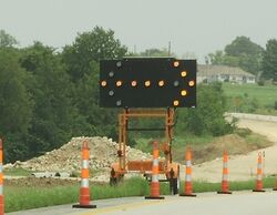
| − | + | '''Picture 1''' shows the correct flashing arrow panel (FAP) display, all lights are working and have the proper intensity.</br> | |
| − | + | :Listed below are items that would make the FAP installation unacceptable: | |
| − | + | ::* More than one lamp is out in stem. | |
| − | + | ::* One or more lamps out in the arrowhead(s) when in the arrow (single- or double-headed). | |
| + | ::* One or more lamps out when in the caution (four corners) modes. | ||
| + | ::* Not appropriate light intensity for work zone conditions, as described in 616.6.61 Arrow Boards. | ||
| − | ===616.19.2. | + | <gallery widths=250px heights=250px position="right" style="text-align:center; font-weight:bold; margin-left:0em" caption="Unacceptable Examples"> |
| + | File:616.19.2.2.9_02.jpg|(2) | ||
| + | File:616.19.2.2.9_03.jpg|(3) | ||
| + | </gallery> | ||
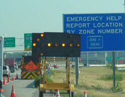
| + | '''Picture 2''' shows one lamp out in the arrowhead which is unacceptable. '''Picture 3''' shows a truck blocking a FAP which is unacceptable. | ||
| − | ====616.19.2. | + | <gallery widths=250px heights=250px position="right" style="text-align:center; font-weight:bold; margin-left:0em" caption="Acceptable Examples"> |
| − | + | File:616.19.2.2.9_04.jpg|(4) | |
| + | File:616.19.2.2.9_05.jpg|(5) | ||
| + | File:616.19.2.2.9_06.jpg|(6) | ||
| + | File:616.19.2.2.9_07.jpg|(7) | ||
| + | </gallery> | ||
| + | The Changeable Message Sign (CMS) messages in '''Pictures 4, 5 and 6''' are acceptable. The messages provide information that static signs cannot provide to the road user. The CMS are placed further upstream of the work zone or at strategic locations to provide information about the upcoming work zone to the road user. The channelizer placement in '''Picture 4, 5 and 6''' shows the correct number of channelizers (5) and the correct placement (100 foot taper). Channelizers are not required if the CMS is more than 15-feet from the edge of shoulder (edge of the roadway if there is no shoulder), beyond ditch line, or behind curb or temporary traffic barrier (TTB) (see [https://www.modot.org/standard-plans-section-600 Std. Plan 616.10 for further details]). '''Picture 7''' shows a Dynamic Message Sign (DMS) providing information of a work zone. Appropriate messages can be found in [[910.3_Dynamic_Message_Signs_(DMS)#910.3.2.10_Acceptable_Abbreviations|EPG 910.3.2.10 Acceptable Abbreviations]]. | ||
| − | : | + | <gallery widths=250px heights=250px position="right" style="text-align:center; font-weight:bold; margin-left:0em" caption="Unacceptable Examples"> |
| − | : | + | File:616.19.2.2.9_08.jpg|(8) |
| − | : | + | File:616.19.2.2.9_09.jpg|(9) |
| − | : | + | File:616.19.2.2.9_10.jpg|(10) |
| + | </gallery> | ||
| + | '''Pictures 8, 9 and 10''' are examples of CMS that are unacceptable due to the lights being either the incorrect intensity or out, as they are not providing a clear and concise message to the road user. | ||
| − | ''' | + | <gallery widths=250px heights=250px position="right" style="text-align:center; font-weight:bold; margin-left:0em" caption="Unacceptable Examples"> |
| + | File:616.19.2.2.9_11.jpg|(11) | ||
| + | File:616.19.2.2.9_12.jpg|(12) | ||
| + | </gallery> | ||
| + | '''Pictures 11 and 12''' show active CMS in nighttime operations. '''Picture 11''', the message is the incorrect intensity and not visible. '''Picture 12''', message is incorrect insensity that makes it too bright and creates a glare. | ||
| − | : | + | <gallery widths=250px heights=250px position="right" style="text-align:center; font-weight:bold; margin-left:0em" caption="Unacceptable Examples"> |
| − | : | + | File:616.19.2.2.9_13.jpg|(13) |
| − | : | + | File:616.19.2.2.9_14.jpg|(14) |
| + | </gallery> | ||
| + | '''Picture 13''' shows a CMS where the lights are out or turned off. If the lights are not working, the CMS is unacceptable. If the CMS is not being used it should be turned off and rotated away from traffic as shown in '''Picture 14''' or removed from the project. Note: The taper length should be 100 feet long with five channelizers. | ||
| − | + | <gallery widths=250px heights=250px position="right" style="text-align:center; font-weight:bold; margin-left:0em" caption="Unacceptable Examples"> | |
| − | + | File:616.19.2.2.9_15.jpg|(15) | |
| − | + | File:616.19.2.2.9_16.jpg|(16) | |
| + | </gallery> | ||
| + | '''Picture 15''' shows a permanent sign blocking the CMS. In '''Picture 16''', the truck should not be placed in front of the CMS board. For '''Picture 16''', the speed limit should not be on a CM. | ||
| − | + | ==616.19.2.3 Transition Area== | |
| + | ===616.19.2.3.1 [[616.6_Temporary_Traffic_Control_Zone_Devices_%28MUTCD_6F%29#616.6.63_Channelizing_Devices_.28MUTCD_6F.63.29|Channelizing Devices]]=== | ||
| + | <gallery widths=250px heights=250px position="right" style="text-align:center; font-weight:bold; margin-left:0em" caption="Acceptable Examples"> | ||
| + | File:616.19.2.3.1_01.jpg|(1) | ||
| + | File:616.19.2.3.1_02.jpg|(2) | ||
| + | File:616.19.2.3.1_03.jpg|(3) | ||
| + | File:616.19.2.3.1_04.jpg|(4) | ||
| + | </gallery> | ||
| + | Trim-line shown in '''Pictures 1 and 2''' are the most commonly used work zone channelizer. '''Picture 3''' shows trim-like channelizers with sequential lights on a nighttime interstate project. '''Picture 4''' shows a drum-like channelizer. Trim-line and drum-like channelizers are commonly ballasted with weights called “rings”, which prevent the channelizers from being blown over. | ||
| − | ====616.19.2. | + | <gallery widths=250px heights=250px position="right" style="text-align:center; font-weight:bold; margin-left:0em" caption="Acceptable Examples"> |
| − | + | File:616.19.2.3.1_05.jpg|(6) | |
| − | + | File:616.19.2.3.1_06.jpg|(6) | |
| − | + | File:616.19.2.3.1_07.jpg|(7) | |
| + | File:616.19.2.3.1_08.jpg|(8) | ||
| + | </gallery> | ||
| + | The direction indicator barricades (DIB) in '''Picture 5''' are commonly used in the merge tapers, but the DIBs in Picture 6 with the panels on the drum-like channelizer are also acceptable. '''Picture 7''' shows DIBs during a nighttime work zone. | ||
| − | + | <gallery widths=250px heights=250px position="right" style="text-align:center; font-weight:bold; margin-left:0em" caption="Acceptable Examples"> | |
| + | File:616.19.2.3.1_08.jpg|(8) | ||
| + | </gallery> | ||
| + | '''Picture 8''' shows tubular markers separating opposing traffic. | ||
| − | + | <gallery widths=250px heights=250px position="right" style="text-align:center; font-weight:bold; margin-left:0em" caption="Unacceptable Examples"> | |
| − | + | File:616.19.2.3.1_09.jpg|(9) | |
| + | File:616.19.2.3.1_10.jpg|(10) | ||
| + | File:616.19.2.3.1_11.jpg|(11) | ||
| + | </gallery> | ||
| + | '''Picture 9''' shows 12-inch cones being used for daytime projects on a minor roadway. '''Picture 10''' shows trim-line channelizers with poor reflectivity that may have limited nighttime visibility. '''Picture 11''' shows a damaged trim-line that is in unacceptable condition. | ||
| − | [[ | + | ==616.19.2.4 Activity Area== |
| − | + | ===616.19.2.4.1 [[616.6_Temporary_Traffic_Control_Zone_Devices_%28MUTCD_6F%29#616.6.70_Temporary_Traffic_Barriers_as_Channelizing_Devices_.28MUTCD_6F.70.29|Temporary Traffic Barriers]]=== | |
| − | + | <gallery widths=250px heights=250px position="right" style="text-align:center; font-weight:bold; margin-left:0em" caption="Acceptable Examples"> | |
| + | File:616.19.2.4.1_01.jpg|(1) | ||
| + | File:616.19.2.4.1_02.jpg|(2) | ||
| + | File:616.19.2.4.1_03.jpg|(3) | ||
| + | </gallery> | ||
| + | '''Pictures 1 - 3''' are acceptable installations of temporary traffic barriers (TTBs). '''Picture 1''' shows a TTB shielding motorists from an edge drop-off and the workers from the vehicles. The TTB in '''Picture 1''' was installed with tie-down straps which prevents tipping of the barrier at a drop-off edge. Stockpiled materials or equipment should not be placed within the 3-foot buffer area behind a tie-down TTB. In '''Picture 1''', the work side of the barrier is free of stockpile material or inactive equipment. The clearance (buffer) behind the TTB will change depending on the different types of TTBs and/or anchoring systems being used. The clearance area is needed to not impede the deflection of the TTB should it be struck by an errant vehicle. '''Picture 2''' shows diverting traffic around a bridge project. '''Picture 3''' shows a TTB separating head-to-head traffic in an urban setting. For selecting proper TTB types on projects, proper installation of TTB and location of TTB, review [[:Category:617_Traffic_Barrier|EPG 617 Traffic Barrier]], [https://www.modot.org/currently-effective-standard-plans Std. Plans. 617.20 and 619.10]. | ||
| − | + | <big>'''3-Loop Type F Connections:'''</big> | |
| − | |||
| − | |||
| − | + | Proper connections: For TTB types, proper connections are essential to prevent separations of the TTBs when hit by an errant vehicle. MoDOT uses the 3-loop Type F barriers on projects. The following examples will show proper connections of the barriers. | |
| + | <gallery widths=250px heights=250px position="right" style="text-align:center; font-weight:bold; margin-left:0em" caption="Acceptable Examples"> | ||
| + | File:616.19.2.4.1_04.jpg|(4) | ||
| + | File:616.19.2.4.1_05.jpg|(5) | ||
| + | </gallery> | ||
| + | '''Pictures 4 and 5''' are examples of proper connections of two 3-loop Type F barriers without bottom washer and retainer bolt and nut. | ||
| − | + | <gallery widths=250px heights=250px position="right" style="text-align:center; font-weight:bold; margin-left:0em" caption="Unacceptable Examples"> | |
| + | File:616.19.2.4.1_06.jpg|(6) | ||
| + | </gallery> | ||
| + | '''In Picture 6''', one 3-loop Type F barrier was turned 180 degrees and the two ends have four loops on top and two loops on the bottom. Care must be taken when installing barrier for proper orientation and loop connections. | ||
| − | [[ | + | ===616.19.2.4.2 [[:Category:612 Impact Attenuators|Impact Attenuators]] / [https://epg.modot.org/index.php?title=616.6_Temporary_Traffic_Control_Zone_Devices_%28MUTCD_6F%29#616.6.86_Crash_Cushions_.28MUTCD_6F.86.29 Crash Cushions] / [[617.1 Temporary Traffic Barriers|End Treatments]]=== |
| − | + | Exposed temporary concrete traffic barrier ends are treated by one of the following methods: Barrier Flare, Barrier Height Transitions, Crash Cushions (Sand Barrel Array and Proprietary Crash Cushion). Additional information is located in [[617.1_Temporary_Traffic_Barriers#617.1.3_Temporary_Concrete_Traffic_Barrier_End_Treatments|EPG 617.1.3 Temporary Concrete Traffic Barrier End Treatments]] and [[:Category:612_Impact_Attenuators|EPG 612 Impact Attenuators]]. | |
| − | |||
| − | ===616.19.2. | + | <big>'''Sand Barrel Array:'''</big> |
| + | <gallery widths=250px heights=250px position="right" style="text-align:center; font-weight:bold; margin-left:0em" caption="Acceptable Examples"> | ||
| + | File:616.19.2.4.2_01.jpg|(1) | ||
| + | File:616.19.2.4.2_02.jpg|(2) | ||
| + | </gallery> | ||
| + | '''Picture 1''' shows an acceptable installation of a sand filled impact attenuator (SFIA), which can be found in [https://www.modot.org/standard-plans-section-600 Std. Plan 612.20] and [[:Category:612_Impact_Attenuators|EPG 612 Impact Attenuators]]. While SFIA is the most common attenuator used, crashworthy end terminals are also available as described in EPG 606.1.3.2 Approved Crashworthy End Terminals . SFIA should be placed a minimum of 24 inches from the end of the blunt end of TTB, guard rail, etc as seen in '''Picture 2'''. | ||
| − | + | <gallery widths=250px heights=250px position="right" style="text-align:center; font-weight:bold; margin-left:0em" caption="Unacceptable Examples"> | |
| − | + | File:616.19.2.4.2_03.jpg|(3) | |
| − | + | File:616.19.2.4.2_04.jpg|(4) | |
| + | </gallery> | ||
| + | The Type 1 object marker in '''Picture 3''' is unacceptable due to the damaged sign sheeting. '''Picture 4''' shows SFIA barrels/modules in a line from the temporary TTB viewpoint. To be crashworthy, the SFIA barrels/modules must have the proper number and meet spacing requirements. The sand should always be kept dry. If water gets into the barrel it can adversely affect the crashworthiness of the device. | ||
| − | + | <gallery widths=250px heights=250px position="right" style="text-align:center; font-weight:bold; margin-left:0em" caption="Unacceptable Examples"> | |
| + | File:616.19.2.4.2_05.jpg|(5) | ||
| + | File:616.19.2.4.2_06.jpg|(6) | ||
| + | File:616.19.2.4.2_07.jpg|(7) | ||
| + | </gallery> | ||
| + | SFIA barrels/modules in '''Picture 5''' are unacceptable because they are located too close to the TTB. Parking vehicles or equipment as shown in '''Picture 6''' is also unacceptable since the vehicles are blocking a crashworthy device. '''Picture 7''' shows a cluttered SFIA installation with plastic material and barrel channelizers. Note the porta-potty and equipment is in close proximity of the SFIA. | ||
| + | ::Note: The porta-potty and equipment should be relocated outside of the clear zone area or behind the protective TTB. | ||
| − | + | <gallery widths=250px heights=250px position="right" style="text-align:center; font-weight:bold; margin-left:0em" caption="Acceptable Examples"> | |
| + | File:616.19.2.4.2_08.jpg|(8) | ||
| + | File:616.19.2.4.2_09.jpg|(9) | ||
| + | File:616.19.2.4.2_10.jpg|(10) | ||
| + | </gallery> | ||
| + | '''Picture 8''' shows an acceptable installation of a traffic barrier height transition for locations with a posted speed limit of 35 mph or less prior to construction. Proprietary crash cushions as shown in '''Pictures 9 and 10''' may be used when there is insufficient width to accommodate sand barrels. | ||
| − | + | <big>'''Truck Mounted Attenuator:'''</big> | |
| − | + | <gallery widths=250px heights=250px position="right" style="text-align:center; font-weight:bold; margin-left:0em" caption="Acceptable Examples"> | |
| − | + | File:616.19.2.4.2_11.jpg|(11) | |
| − | + | </gallery> | |
| − | [[ | + | '''Picture 11''' is the TMA delineation style that is acceptable on projects. Additional information is in [[:Category:612_Impact_Attenuators|EPG 612 Impact Attenuators]]. |
| − | |||
| − | |||
| − | ===616.19.2. | + | ==616.19.2.5 Additional Guidance== |
| + | ===616.19.2.5.1 Temporary [[616.6_Temporary_Traffic_Control_Zone_Devices_%28MUTCD_6F%29#616.6.77_Pavement_Markings_.28MUTCD_6F.77.29|Paint]] / [[616.6_Temporary_Traffic_Control_Zone_Devices_%28MUTCD_6F%29#616.6.78_Temporary_Markings_.28MUTCD_6F.78.29|Tape]] / [[616.6_Temporary_Traffic_Control_Zone_Devices_%28MUTCD_6F%29#616.6.79_Temporary_Raised_Pavement_Markers_.28MUTCD_6F.79.29|Pavement Markers]]=== | ||
| + | <gallery widths=250px heights=250px position="right" style="text-align:center; font-weight:bold; margin-left:0em" caption="Acceptable Examples"> | ||
| + | File:616.19.2.5.1_01.jpg|(1) | ||
| + | File:616.19.2.5.1_02.jpg|(2) | ||
| + | File:616.19.2.5.1_03.jpg|(3) | ||
| + | </gallery> | ||
| + | Guidelines for pavement markings are located in [[:Category:620_Pavement_Marking|EPG 620 Pavement Marking]], [https://www.modot.org/missouri-standard-specifications-highway-construction Missouri Standard Specifications Sec. 620] and [https://www.modot.org/standard-plans-section-600 Std. Plans. 620.00 and 620.10]. '''Pictures 1, 2 and 3''' are examples of temporary pavement markings (TPM) meeting specifications and standards. '''Picture 1''' shows TPM for center line and edge lines. '''Picture 2''' shows a roadway with TPM for a roadway with only a center line stripe during a nighttime review. '''Picture 3''' shows TPM of a solid line to keep traffic in the designated lanes during a nighttime review. | ||
| − | + | <gallery widths=250px heights=250px position="right" style="text-align:center; font-weight:bold; margin-left:0em" caption="Unacceptable Examples"> | |
| − | + | File:616.19.2.5.1_04.jpg|(4) | |
| − | + | File:616.19.2.5.1_05.jpg|(5) | |
| − | + | </gallery> | |
| − | + | The roadway in '''Picture 4''' should have temporary center line pavement markers or stripes. '''Picture 5''' shows a project using half of the permanent center line stripe as the pavement marking and not place TPM until the other lane is overlaid, which is unacceptable. | |
| − | |||
| − | |||
| − | |||
| − | ===616.19.2. | + | <gallery widths=250px heights=250px position="right" style="text-align:center; font-weight:bold; margin-left:0em" caption="Unacceptable Examples"> |
| + | File:616.19.2.5.1_06.jpg|(6) | ||
| + | File:616.19.2.5.1_07.jpg|(7) | ||
| + | File:616.19.2.5.1_08.jpg|(8) | ||
| + | </gallery> | ||
| + | Pavement marking installation and removal should be done carefully as not to misdirect the road user. The TPM ('''Picture 6''') were intended to move the traffic to a temporary shoulder lane. | ||
| + | ::Note: The permanent center line should have been removed to avoid road user confusion. | ||
| + | '''Picture 7''' shows a right turn lane line partially removed, care should be given to completely remove all conflicting markings in accordance with the plans and specifications. In '''Picture 8''' shows conflicting edge lines across the bridge. | ||
| − | |||
| − | |||
| − | |||
| − | + | <gallery widths=250px heights=250px position="right" style="text-align:center; font-weight:bold; margin-left:0em" caption="Unacceptable Examples"> | |
| − | + | File:616.19.2.5.1_09.jpg|(9) | |
| − | + | File:616.19.2.5.1_10.jpg|(10) | |
| + | File:616.19.2.5.1_11.jpg|(11) | ||
| + | File:616.19.2.5.1_12.jpg|(12) | ||
| + | </gallery> | ||
| + | '''Pictures 9 - 12''' are examples of pavement marking removal. Care should be taken not to scar the pavement when removing markings. '''Pictures 11 and 12''' shows lane lines leading motorists into the channelization. The dashed line should stop at a point when the two lanes are designated to end. | ||
| − | ===616.19.2. | + | ===616.19.2.5.2 [[616.7_Type_of_Temporary_Traffic_Control_Zone_Activities_(MUTCD_6G)|Traffic Management]]=== |
| + | To provide adequate traffic management many tools are available which includes but not limited to the following: signs, channelizing devices, changeable and dynamic message signs, intelligent transportation systems (ITS), detours, law enforcement, flagging operation, etc. | ||
| − | [[ | + | [[616.13_Work_Zone_Capacity,_Queue_and_Travel_Delay|EPG 616.13 Work Zone Capacity, Queue and Travel Delay]] and [[616.14_Work_Zone_Safety_and_Mobility_Policy|EPG 616.14 Work Zone Safety and Mobility Policy]] have additional information for traffic management policies and tools. |
| − | |||
| − | |||
| − | ===616.19.2. | + | <gallery widths=250px heights=250px position="right" style="text-align:center; font-weight:bold; margin-left:0em" caption="Acceptable Examples"> |
| + | File:616.19.2.5.2_01.jpg|(1) | ||
| + | File:616.19.2.5.2_02.jpg|(2) | ||
| + | File:616.19.2.5.2_03.jpg|(3) | ||
| + | </gallery> | ||
| + | '''Pictures 1 - 3''' are acceptable examples of traffic management. '''Picture 1''' shows a long-term stationary work zone that is providing a well-defined merge taper with adequate striping and channelizers. '''Picture 2''' shows a well-marked crossover. The temporary work zone in '''Picture 3''' shows proper delineation for head to head traffic while providing access to area businesses. | ||
| − | + | <gallery widths=250px heights=250px position="right" style="text-align:center; font-weight:bold; margin-left:0em" caption="Acceptable Examples"> | |
| + | File:616.19.2.5.2_04.jpg|(4) | ||
| + | File:616.19.2.5.2_05.jpg|(5) | ||
| + | File:616.19.2.5.2_06.jpg|(6) | ||
| + | </gallery> | ||
| + | '''Pictures 4 and 5''' are examples of providing the road user information of how wide the lanes are before entering the workzone. The CMS message provides adequate information to allow the road user to make a decision on the proper lane to use. '''Picture 6''' is an example of height restriction for the road user. | ||
| − | ===616.19.2. | + | ===616.19.2.5.3 Rejected Stickers for TTC Devices=== |
| − | + | <div style="float: right; margin-left: 30px; margin-bottom: 30px;"> | |
| − | + | [[image:616.19.2.5.3_02.jpg|center|thumb|<center>'''Rejected Sticker location examples''']] | |
| − | + | </div> | |
| − | + | [[image:616.19.2.5.3_01.jpg|left|thumb|<center>'''R11-52 REJECTED Decal (Order No. MoDOT 46)'''</center>]] | |
| − | |||
| − | |||
| − | |||
| − | |||
| − | |||
| − | |||
| − | [[image:616.19.2. | ||
| − | |||
| − | |||
| − | |||
| − | |||
| − | |||
| − | |||
| − | |||
| − | [[image:616.19.2. | ||
| − | |||
| − | |||
| − | |||
| − | |||
| − | |||
| − | |||
| − | |||
REJECTED stickers, with appropriate month and year designated, may be used by MoDOT personnel to identify unacceptable temporary traffic control devices. For barricades, channelizing devices and signs, the sticker should be located on the front-, left- and lower-most retroreflective area on the device. For other devices, the sticker should be located in a conspicuous place on the device. | REJECTED stickers, with appropriate month and year designated, may be used by MoDOT personnel to identify unacceptable temporary traffic control devices. For barricades, channelizing devices and signs, the sticker should be located on the front-, left- and lower-most retroreflective area on the device. For other devices, the sticker should be located in a conspicuous place on the device. | ||
| − | |||
| − | |||
| − | |||
[[Category:616 Temporary Traffic Control]] | [[Category:616 Temporary Traffic Control]] | ||
Latest revision as of 08:19, 1 May 2024
Contents
- 1 616.19.1 Quality Requirements
- 2 616.19.2 Quality Standards
- 2.1 616.19.2.1 General
- 2.2 616.19.2.2 Advance Warning Area
- 2.2.1 616.19.2.2.1 Sign Placement and Installation
- 2.2.2 616.19.2.2.2 Sign, Flag and AWRS Quality
- 2.2.3 616.19.2.2.3 Proper Sign Color
- 2.2.4 616.19.2.2.4 Information From the Signs
- 2.2.5 616.19.2.2.5 Ballasting of Signs
- 2.2.6 616.19.2.2.6 Additional Sign Examples
- 2.2.7 616.19.2.2.7 Sign Coverings
- 2.2.8 616.19.2.2.8 Barricades
- 2.2.9 616.19.2.2.9 Changeable Message Sign / Flashing Arrow Panels / Traffic Signals
- 2.3 616.19.2.3 Transition Area
- 2.4 616.19.2.4 Activity Area
- 2.5 616.19.2.5 Additional Guidance
- Quality Standards for Temporary Traffic Control Devices (This Work Zone flyer shows the top deficient Temporary Traffic Control Devices)
Temporary traffic control devices (TTCDs) are an essential part of highway work zones. TTCDs warn motorists of hazards, advise them of the proper path through the work area, delineate areas where they may not operate and separate motorists from workers and opposing traffic.
There are many factors that ensure the success of these functions; the placement and condition of each TTCD are two important factors. TTCDs that are worn, damaged or improperly installed will significantly lower the overall quality of a work zone. Clean, legible, properly installed TTCDs will command the respect of the traveling public.
These quality standards are intended as a resource to determine if TTCDs are meeting current traffic needs in terms of legibility, visibility and other safety and mobility requirements for TTCDs (e.g., impact attenuators, truck-mounted attenuators, signs, channelizers, barricades, changeable message signs, flashing arrow panels, work zone traffic signals, temporary pavement marking, temporary traffic barrier, etc.) deployed on the state highway system. Effective application of these quality standards will benefit everyone that works in or navigates through work zones on the state highway system.
616.19.1 Quality Requirements
TTCDs shall be installed and maintained in an acceptable condition. Unless specified otherwise, this requirement does not mandate the use of new devices, but it does necessitate the use of functional devices. Unacceptable devices shall be replaced or corrected in accordance with the contract documents or in the absence of a contract (e.g., permit projects) as directed by MoDOT’s representative.
When reviewing work zones, the MoDOT Work Zone Inspection Checklist is a valuable tool for determining the safety and mobility performance of all work zones including federal and state funded contracts, state maintenance, and permit projects.
Document all deficiencies on the checklist along with any corrective action(s) taken and/or the time/date that appropriate personnel was contacted to initiate the corrective action(s).
The work zone should be re-inspected to ensure that all deficiencies have been corrected.
616.19.2 Quality Standards
616.19.2.1 General
All TTCDs shall be:
- In conformance with the requirements of the MUTCD and MoDOT Standards.
- Installed and maintained at locations and in orientations that maximize safety and minimize disruption to traffic flow. Aligned with the road user’s line of sight.
- Positioned in a manner not to obstruct other traffic control devices.
- Free of dents, holes, deformations, abrasions, tears, marks, stains, residues, fading or other deficiencies that adversely affects the operational performance including the crashworthiness of a device.
- Properly covered, turned, stowed, or removed when not in use. Visible during daytime and nighttime operations.
If TTCDs such as signs, channelizers, etc. have damage resulting in 25% or more deterioration of the lettering, border, or symbol, the device shall be replaced in an agreed upon time with the engineer. Furthermore, if the device is experiencing a reduction in retroreflectivity by 25% or more due to residue, fading, or damage, the device shall be replaced in an agreed upon time with the engineer.
616.19.2.2 Advance Warning Area
616.19.2.2.1 Sign Placement and Installation
- Acceptable Examples
(1)
(2)
(3)


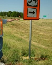
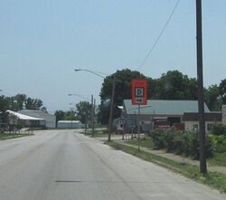
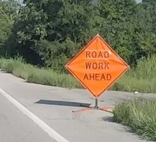
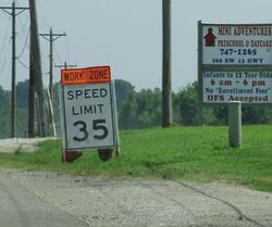
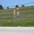
The post mounted sign shown in Picture 1 is mounted 5-foot in height from the edge of the roadway to the bottom of the sign as required for a rural location. For urban locations, post mounted signs shall be 7-feet as shown in Picture 2. For short term projects temporary signs, as shown in Picture 3, may have a minimum height of one foot. For additional information on sign installation and heights see Standard (Std.) Plan 616.10].
- Acceptable Examples
(4)

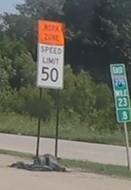
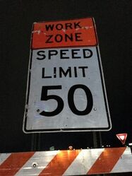
When used, speed limit (regulatory) signs shall be installed at a 5-foot (rural area) or a 7-foot (urban area) mounting height as shown in Picture 4. Information on the mounting height of the signs is in Std. Plan 616.10. The WORK ZONE PLAQUE (Go20-5Ap) shall be 2-foot height as shown in EPG 616.6.12 Work Zone and Higher Fines Signs and Plaques (MUTCD 6F12).
- Unacceptable Examples
(5)

The mounting height and the WORK ZONE plaque (GO20-5aP) of the sign in Pictures 5 is not compliant with MoDOT/MUTCD standards.
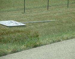
Lateral Sign Location: Sign locations shall be located 6-12 feet from the edge of the paved travel lane or shoulder as shown in Std. Plan 616.10. Before installing signs, the project site should be reviewed to agree on the best location for signs. When stubs are not driven deep enough into the ground a sign may lean or fall after a period of time. Due to terrain slopes, curves, shoulder widths, duration of projects, signs may deviate from recommended placement to achieve a plumb position, be sure to document.
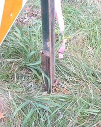
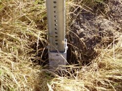
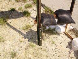
Post Installations:
- Acceptable Examples
(6)

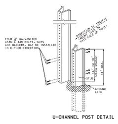
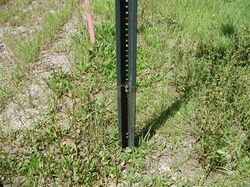
Picture 6 illustrates the proper installation for posts. The complete U-channel Post details are located in Std. Plan 616.10.
- Acceptable Examples
(7)

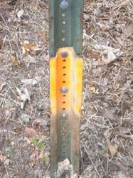
Picture 7 is an example of a correct U-channel post splice, which shows the four bolts in the proper location, correct stub height and splice overlap.
- Note: The bolts can be installed in either direction.
- Note: Missouri One-Call shall always be notified prior to installing any signpost into the ground.
- Note: The bolts can be installed in either direction.
- Unacceptable Examples
(8)
(9)


The stub height and splice overlap in Picture 8 is correct, but the 4-bolts are not in the proper locations. Picture 9 shows inadequate stub height and overlap and the signpost is not on the correct side of the stub.
- Unacceptable Examples
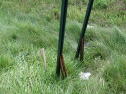
(10)

(11)
(12)


The installations in Pictures 10-12 are unacceptable. Picture 10 shows an installation of only 1 bolt per signpost leg. Picture 11 shows an installation of one post mounted leg and one skid mounted leg. Picture 12 shows two splices when only one splice is allowed.
- Acceptable Examples
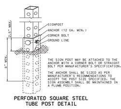
(13)

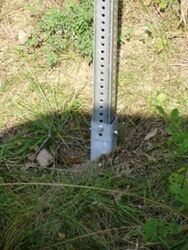
Picture 13 is a Perforated Square Steel Tube Post (PSST) with more details located in Std. Plan 616.10.
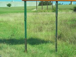
- Acceptable Examples
(14)
(15)


Pictures 14 and 15 show proper installation of a PSST post. The PSST post does not have to use the corner bolt but can be bolted either with one or two straight bolts. However, the corner bolt minimizes movement of the post within the tubes.
- Note: Missouri One-Call shall always be notified prior to installing any signpost into the ground.
- Unacceptable Examples
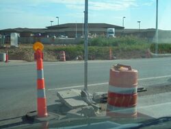
(16)

Picture 16 shows a stub higher than the 2-inches maximum and the bolt should be bolted through the two posts.
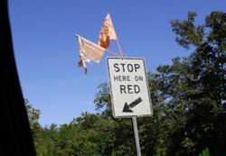
616.19.2.2.2 Sign, Flag and AWRS Quality
- Acceptable Examples

(1)
(2)
(3)


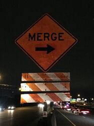
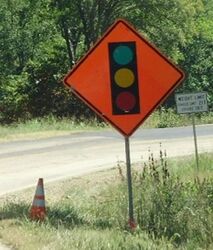
The signs in Pictures 1, 2 and 3 are considered in good quality. Supplemental devices such as flags and/or a cone may be placed next to a sign. Picture 2 is an example of the proper placement of a FLAGGER (WO20-7) sign, with the optional flags, in advance of the hill versus after the hill. In urban areas with barrier walls and narrow shoulders, a truncated sign may be used as shown in Picture 3.
- Note: TTCDs may be highly visible during the day but may not be at night due to inadequate retroreflectivity. MoDOT and Contractor representatives should drive through the work zone at night to check nighttime visibility.
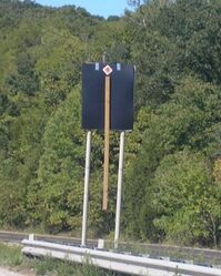
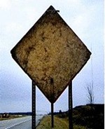
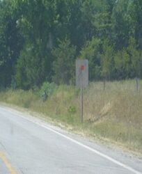
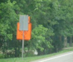
- Unacceptable Examples
(4)

(5)

(6)
(7)

(8)
(9)


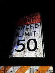
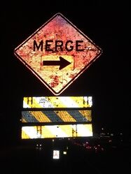
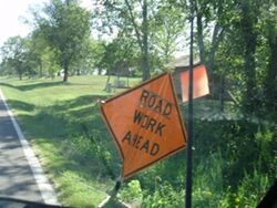
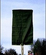
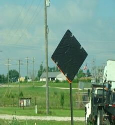
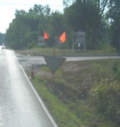
Pictures 4-7 are in unacceptable condition. Dirty or damaged signs should be cleaned, repaired, or replaced before being installed. When cleaning, follow manufacturer’s recommendations, so the daytime and nighttime visibility of the sign is not adversely impacted. The MEN WORKING sign (Picture 8) should be replaced with worker symbol sign or WORKERS sign (WO-21-1 or 1a) to meet current standards. Picture 9 shows unacceptable flags, if used, deteriorated flags should be replaced.
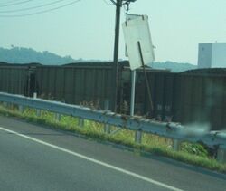
- Unacceptable Examples
(10)
(11)
(12)
(13)


Pictures 10 - 13 are examples of unacceptable nighttime visibility. Proper storing, transporting, and covering signs is crucial to minimizing deficiencies.
- Acceptable Examples
(14)
(15)
(16)


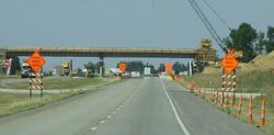
Advance Warning Rail System (AWRS) shall be installed on the first advance warning sign (Road/Bridge Work Ahead) on long-term stationary projects. The barricade stripes shall slope downward toward the roadway as shown above. Picture 14 is an example of acceptable AWRS installations. When a Type 3 Barricade is used with a sign as shown Picture 15, the barricade shall be located between 7 to 10 feet from the sign (to be crashworthy). Either a 4-foot or 8-foot barricade may be used. A 4 foot AWRS on single post is acceptable as shown in Picture 16 provided the signpost has been sized to accommodate the added weight and square footage of the AWRS.
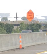
616.19.2.2.3 Proper Sign Color
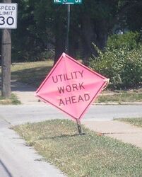
Sign colors are reserved for specific applications. Orange is reserved for temporary traffic control, pink for incident management, yellow for warning, and red/black/white for regulatory signs.
- Acceptable Examples
(1)

Fluorescent orange signs as shown on the right in Picture 1 are required for MoDOT contract and maintenance projects. Permit projects may use engineering grade sheeting as shown on the left side of Picture 1 provided they meet MUTCD reflectivity requirements.
- Unacceptable Examples
(2)
(3)

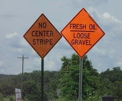
The UTILITY WORK AHEAD (WO21-7) and the LANE CLOSED AHEAD (WO20-5) signs in Pictures 2 and 3 should be orange not pink or yellow. Note: Using tape on a sign can destroy the retroreflectivity of the sign as shown in Picture 3.
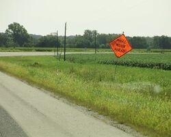
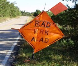
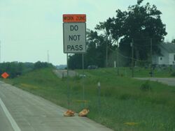
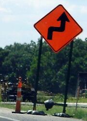
616.19.2.2.4 Information From the Signs
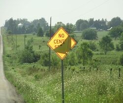
- Unacceptable Examples
(1)
(2)
(3)


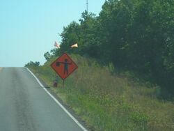
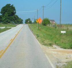
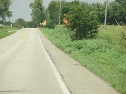
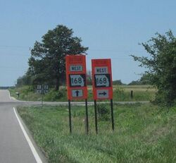
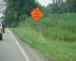
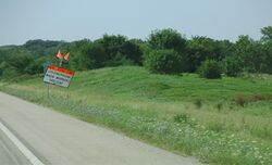
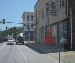
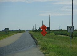
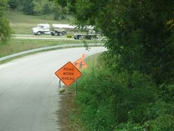
Pictures 1 - 3 are examples of signs that are visually obstructed or providing conflicting information. Picture 1 should be moved upstream from the permanent curve warning sign with written documentation as to why the sign was moved. The advance warning sign in Picture 2 should be relocated upstream of the tree or the tree should be trimmed (if within MoDOT ROW) to provide the required visibility. Picture 3 shows detour signs that are providing two detour options for the same route. To reduce road user confusion, it is best to provide only one detour option.
- Acceptable Examples

(4)

Picture 4 is an acceptable use of the ROAD WORK NEXT XX MILES (GO20-1), as it uses whole numbers only. Do not use decimals of a mile.
- Unacceptable Examples
(5)
(6)


Pictures 5 and 6 are unacceptable signs because the specified miles are not listed as whole numbers.
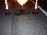
616.19.2.2.5 Ballasting of Signs
- Acceptable Examples
(1)

For portable signs, ballasting should be limited to one sandbag layer on the sign legs as shown in Picture 1.
- Unacceptable Examples
(2)
(3)


The use of channelizer rings as shown in Pictures 2 and 3 are unacceptable as the crashworthiness has not been verified.
- Acceptable Examples
(4)
(5)


For skid mounted signs, ballasting should be limited to one sandbag layer on the sign legs as shown in Pictures 4 and 5. Picture 5 shows an acceptable use of ballasting for a skid mounted sign. The crossbar (Picture 5) should be no higher than 12 inches (one sandbag over the crossbar is acceptable).
- Unacceptable Examples

(6)
(7)
(8)


Picture 6 shows a large mound of sandbags, which if hit could present a ramping situation for vehicles. Picture 7 has two sandbags on the crossbar which is unacceptable and utilizes two types of mounting styles. In Picture 8, concrete is being used to ballast the sign, which is not crashworthy and is unacceptable.
616.19.2.2.6 Additional Sign Examples
- Unacceptable Examples
(1)
(2)
(3)
(4)


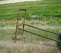
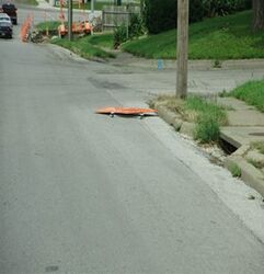
Picture 1 shows a crossbar above the 18-inch maximum height without sandbag or 12-inch maximum height with sandbag. Picture 2 shows a skid mounted sign stand laying on the ground attached to the sign post. The skid mount should be removed from the sign post and placed flat on the ground. As shown, this sign stand is not crashworthy. Picture 3 shows a sign laying in the street. This sign should be placed in a better location. Picture 4 shows two crashworthy signs that have been placed closer than the recommended 7-10 feet spacing making them not crashworthy. The 7-10 feet spacing allows the signs to act independently of each other to meet crashworthy criteria.
- Unacceptable Examples
(5)
(6)
(7)


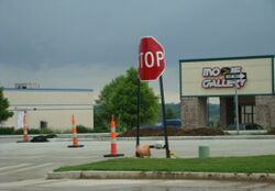
Picture 5 is an example of a STOP (R1-1) sign not having a full face visible to the road user. The sign in Picture 6 is leaning and should be plumb. The sign in Picture 7 could be moved upstream or downstream to achieve a plumb position. Be sure to document the location change, such as, “After reviewing the sign in the original position, the sign was moved 100-feet upstream to be achieve a plumb position”.
- Unacceptable Examples
(8)
(9)
(10)


Sign placement in urban areas can impede non-motorized travel as shown in Picture 8. Accommodations should be made for all modes of travel including non-motorized traffic such as, pedestrians and bicyclists. The signpost in Picture 9 should have only one sign. A permanently posted SPEED LIMIT (R2-1) sign, as shown in Picture 10, should not be removed. If the posted speed limit is lowered, the proper procedure is to cover the sign as described in 616.19.2.2.7 Sign Coverings.
- Unacceptable Examples
(11)
(12)


Picture 11 shows an example of two work zones placed inside each other. Proper coordination should be one of the highest considerations when work zones overlap each other. Picture 12 shows the signal head upside down.
616.19.2.2.7 Sign Coverings
- Acceptable Examples
(1)
(2)
(3)


Pictures 1 - 3 show examples of signs properly covered with plastic sign cover, plastic taped securely to the sign without direct contact with the sign face and a roll-up sign folded down. Materials used should not allow the sign face to “bleed through” during daytime or nighttime use. Pictures 1 and 2 adequately cover the face of the sign.
- Acceptable Examples
(4)
(5)
(6)


Pictures 4 - 6 are examples of acceptable materials to cover signs. Materials range from rubber that is used for mud flaps or a matching sized sign cover. The sign covers should be adequately secured to the host sign assembly and sized to match the sign to completely cover the face. The cover should be constructed with non-metallic (such as wooden, plastic, etc.) handles and spacers to keep the sign covers from damaging the sign face.
- Unacceptable Examples
(7)
(8)

(9)
(10)


The sign cover in Picture 7 is not securely fastened and does not have a non-metallic handle. Picture 8 shows the sign cover not matching the shape of the host sign, which could provide conflicting information to the road user. Picture 9 shows duct tape covering part of the sign wording, which can damage the sign retroreflectivity. Picture 10 shows an example of unacceptable use of plastic taped to the sign. The plastic is thin which illustrates the “bleed through” of the message and it is falling off and the sign.
616.19.2.2.8 Barricades
- Acceptable Examples
(1)
(2)


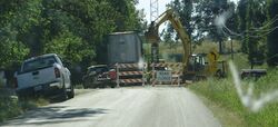
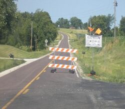
Picture 1 shows the proper placement of Type 3 barricades on a full roadway closure, including stripe direction. The barricade installation also provides an adequate buffer space to the work area. At some locations, barricades may have to be located at the bridge ends or work area due to side roads. Picture 2 shows equipment behind the barricades.
- Unacceptable Examples
(3)

(4)


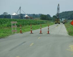
Picture 3 shows a barricade installation located after the private entrance and before the bridge end, not leaving enough buffer space. In Picture 4, notice the left barricade stripes are angling to the left instead of to the right.
- Unacceptable Examples
(5)
(6)
(7)


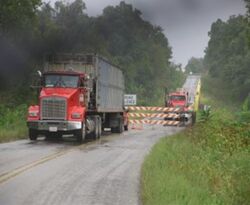
Picture 5 shows Type 3 barricades that were moved to let vehicles into the work zone. Picture 6 shows a haul truck entering a work zone and leaving the barricades open which could allow the road user to follow the haul truck. Picture 7 shows the barricades staggered to allow haul trucks in and out of the work zone which is not permitted.
- Unacceptable Examples
(8)
(9)


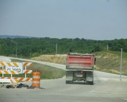
Pictures 8 and 9 show trucks parked in front of barricades, obstructing them from oncoming traffic. Note: Equipment or vehicles should not be parked in front of barricades they should be moved to an appropriate location (i.e., behind the barricades).
- Acceptable Examples
(10)
(11)


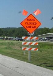
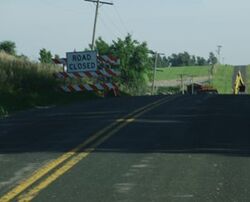
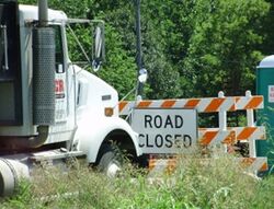
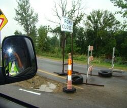
Picture 10 shows a soft closure which is intended to allow local traffic only to get to the desired destination before the full closure. One barricade and ROAD CLOSED (R11-2) sign as shown in Picture 11 can be used to inform the road user of closures, which when used should be located on the shoulder.
- Unacceptable Examples
(12)

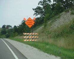
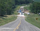
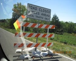
The barricade in Picture 12 is directing the road user into the opposite lane and not directing them back into the proper lane of travel with another barricade in the opposite lane. A single “ROAD CLOSED XX MILES AHEAD” (R11-3a) sign is allowed without barricades. Note: A full barricade closure is required at the work area.
- Unacceptable Examples
(13)
(14)
(15)
(16)


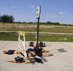
The ballasting in Pictures 13 - 16 show unacceptable applications. Tires should not be used as ballast. Sandbags are allowed if they are not stacked on each other (i.e.,a single layer to meet crashworthiness). As shown in Pictures 13 - 15, the signs may be placed behind the Type 3 barricades. To be crashworthy, the sign and barricade should be separated by 7 to 10 feet from each other so each device can act independently if struck by a vehicle. Picture 16 shows old barrel rings around the legs of the barricades. If rings are used, only one is allowed per leg.
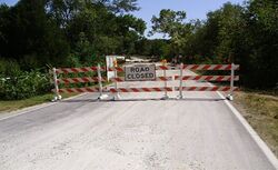
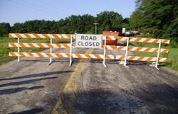
- Unacceptable Examples
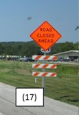
(17)
(18)
(19)


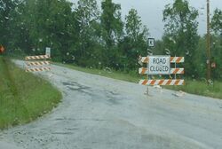
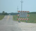
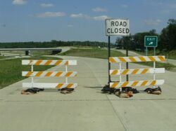
The road closures in Pictures 17 -19 are unacceptable installations, the Type 3 barricades should cover the full roadway width to meet the requirements for a full road closure. The damaged rail sheeting on the barricades in Picture 19 is unacceptable.
616.19.2.2.9 Changeable Message Sign / Flashing Arrow Panels / Traffic Signals
- Acceptable Examples
(1)

Picture 1 shows the correct flashing arrow panel (FAP) display, all lights are working and have the proper intensity.
- Listed below are items that would make the FAP installation unacceptable:
- More than one lamp is out in stem.
- One or more lamps out in the arrowhead(s) when in the arrow (single- or double-headed).
- One or more lamps out when in the caution (four corners) modes.
- Not appropriate light intensity for work zone conditions, as described in 616.6.61 Arrow Boards.
- Unacceptable Examples
(2)

(3)


Picture 2 shows one lamp out in the arrowhead which is unacceptable. Picture 3 shows a truck blocking a FAP which is unacceptable.
- Acceptable Examples
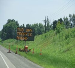
(4)
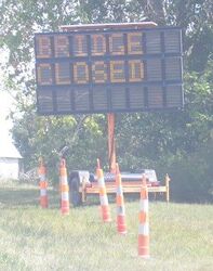
(5)
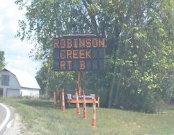
(6)
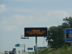
(7)


The Changeable Message Sign (CMS) messages in Pictures 4, 5 and 6 are acceptable. The messages provide information that static signs cannot provide to the road user. The CMS are placed further upstream of the work zone or at strategic locations to provide information about the upcoming work zone to the road user. The channelizer placement in Picture 4, 5 and 6 shows the correct number of channelizers (5) and the correct placement (100 foot taper). Channelizers are not required if the CMS is more than 15-feet from the edge of shoulder (edge of the roadway if there is no shoulder), beyond ditch line, or behind curb or temporary traffic barrier (TTB) (see Std. Plan 616.10 for further details). Picture 7 shows a Dynamic Message Sign (DMS) providing information of a work zone. Appropriate messages can be found in EPG 910.3.2.10 Acceptable Abbreviations.
- Unacceptable Examples
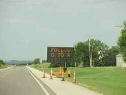
(8)
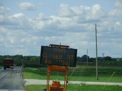
(9)
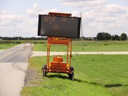
(10)


Pictures 8, 9 and 10 are examples of CMS that are unacceptable due to the lights being either the incorrect intensity or out, as they are not providing a clear and concise message to the road user.
- Unacceptable Examples
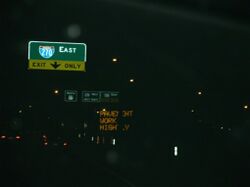
(11)
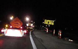
(12)


Pictures 11 and 12 show active CMS in nighttime operations. Picture 11, the message is the incorrect intensity and not visible. Picture 12, message is incorrect insensity that makes it too bright and creates a glare.
- Unacceptable Examples
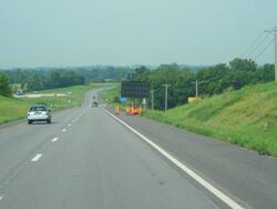
(13)
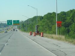
(14)


Picture 13 shows a CMS where the lights are out or turned off. If the lights are not working, the CMS is unacceptable. If the CMS is not being used it should be turned off and rotated away from traffic as shown in Picture 14 or removed from the project. Note: The taper length should be 100 feet long with five channelizers.
- Unacceptable Examples
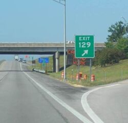
(15)
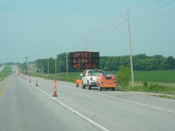
(16)


Picture 15 shows a permanent sign blocking the CMS. In Picture 16, the truck should not be placed in front of the CMS board. For Picture 16, the speed limit should not be on a CM.
616.19.2.3 Transition Area
616.19.2.3.1 Channelizing Devices
- Acceptable Examples
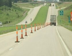
(1)
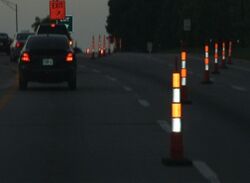
(2)
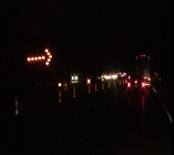
(3)
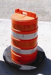
(4)


Trim-line shown in Pictures 1 and 2 are the most commonly used work zone channelizer. Picture 3 shows trim-like channelizers with sequential lights on a nighttime interstate project. Picture 4 shows a drum-like channelizer. Trim-line and drum-like channelizers are commonly ballasted with weights called “rings”, which prevent the channelizers from being blown over.
- Acceptable Examples
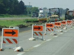
(6)
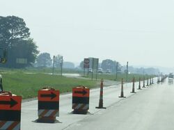
(6)
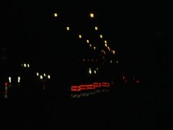
(7)
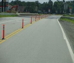
(8)


The direction indicator barricades (DIB) in Picture 5 are commonly used in the merge tapers, but the DIBs in Picture 6 with the panels on the drum-like channelizer are also acceptable. Picture 7 shows DIBs during a nighttime work zone.
- Acceptable Examples
(8)
Picture 8 shows tubular markers separating opposing traffic.
- Unacceptable Examples
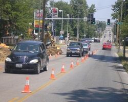
(9)
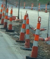
(10)
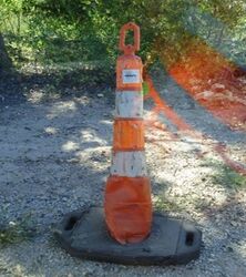
(11)


Picture 9 shows 12-inch cones being used for daytime projects on a minor roadway. Picture 10 shows trim-line channelizers with poor reflectivity that may have limited nighttime visibility. Picture 11 shows a damaged trim-line that is in unacceptable condition.
616.19.2.4 Activity Area
616.19.2.4.1 Temporary Traffic Barriers
- Acceptable Examples
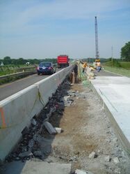
(1)
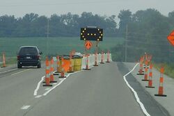
(2)
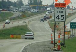
(3)


Pictures 1 - 3 are acceptable installations of temporary traffic barriers (TTBs). Picture 1 shows a TTB shielding motorists from an edge drop-off and the workers from the vehicles. The TTB in Picture 1 was installed with tie-down straps which prevents tipping of the barrier at a drop-off edge. Stockpiled materials or equipment should not be placed within the 3-foot buffer area behind a tie-down TTB. In Picture 1, the work side of the barrier is free of stockpile material or inactive equipment. The clearance (buffer) behind the TTB will change depending on the different types of TTBs and/or anchoring systems being used. The clearance area is needed to not impede the deflection of the TTB should it be struck by an errant vehicle. Picture 2 shows diverting traffic around a bridge project. Picture 3 shows a TTB separating head-to-head traffic in an urban setting. For selecting proper TTB types on projects, proper installation of TTB and location of TTB, review EPG 617 Traffic Barrier, Std. Plans. 617.20 and 619.10.
3-Loop Type F Connections:
Proper connections: For TTB types, proper connections are essential to prevent separations of the TTBs when hit by an errant vehicle. MoDOT uses the 3-loop Type F barriers on projects. The following examples will show proper connections of the barriers.
- Acceptable Examples
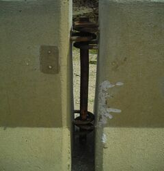
(4)
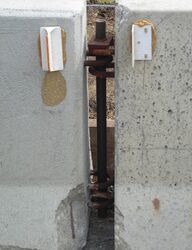
(5)


Pictures 4 and 5 are examples of proper connections of two 3-loop Type F barriers without bottom washer and retainer bolt and nut.
- Unacceptable Examples
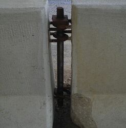
(6)

In Picture 6, one 3-loop Type F barrier was turned 180 degrees and the two ends have four loops on top and two loops on the bottom. Care must be taken when installing barrier for proper orientation and loop connections.
616.19.2.4.2 Impact Attenuators / Crash Cushions / End Treatments
Exposed temporary concrete traffic barrier ends are treated by one of the following methods: Barrier Flare, Barrier Height Transitions, Crash Cushions (Sand Barrel Array and Proprietary Crash Cushion). Additional information is located in EPG 617.1.3 Temporary Concrete Traffic Barrier End Treatments and EPG 612 Impact Attenuators.
Sand Barrel Array:
- Acceptable Examples
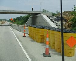
(1)
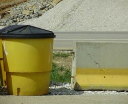
(2)


Picture 1 shows an acceptable installation of a sand filled impact attenuator (SFIA), which can be found in Std. Plan 612.20 and EPG 612 Impact Attenuators. While SFIA is the most common attenuator used, crashworthy end terminals are also available as described in EPG 606.1.3.2 Approved Crashworthy End Terminals . SFIA should be placed a minimum of 24 inches from the end of the blunt end of TTB, guard rail, etc as seen in Picture 2.
- Unacceptable Examples
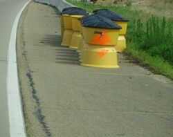
(3)
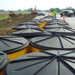
(4)


The Type 1 object marker in Picture 3 is unacceptable due to the damaged sign sheeting. Picture 4 shows SFIA barrels/modules in a line from the temporary TTB viewpoint. To be crashworthy, the SFIA barrels/modules must have the proper number and meet spacing requirements. The sand should always be kept dry. If water gets into the barrel it can adversely affect the crashworthiness of the device.
- Unacceptable Examples
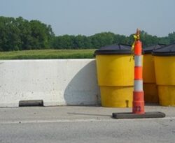
(5)
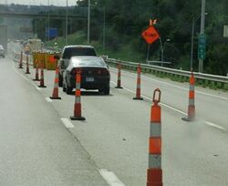
(6)
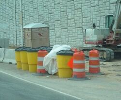
(7)


SFIA barrels/modules in Picture 5 are unacceptable because they are located too close to the TTB. Parking vehicles or equipment as shown in Picture 6 is also unacceptable since the vehicles are blocking a crashworthy device. Picture 7 shows a cluttered SFIA installation with plastic material and barrel channelizers. Note the porta-potty and equipment is in close proximity of the SFIA.
- Note: The porta-potty and equipment should be relocated outside of the clear zone area or behind the protective TTB.
- Acceptable Examples
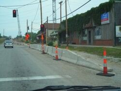
(8)
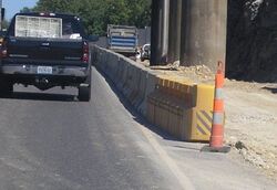
(9)
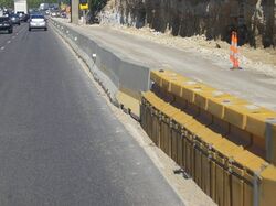
(10)


Picture 8 shows an acceptable installation of a traffic barrier height transition for locations with a posted speed limit of 35 mph or less prior to construction. Proprietary crash cushions as shown in Pictures 9 and 10 may be used when there is insufficient width to accommodate sand barrels.
Truck Mounted Attenuator:
- Acceptable Examples
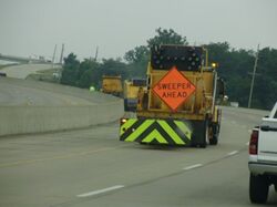
(11)

Picture 11 is the TMA delineation style that is acceptable on projects. Additional information is in EPG 612 Impact Attenuators.
616.19.2.5 Additional Guidance
616.19.2.5.1 Temporary Paint / Tape / Pavement Markers
- Acceptable Examples
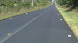
(1)
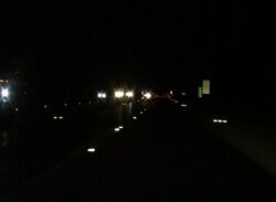
(2)

(3)


Guidelines for pavement markings are located in EPG 620 Pavement Marking, Missouri Standard Specifications Sec. 620 and Std. Plans. 620.00 and 620.10. Pictures 1, 2 and 3 are examples of temporary pavement markings (TPM) meeting specifications and standards. Picture 1 shows TPM for center line and edge lines. Picture 2 shows a roadway with TPM for a roadway with only a center line stripe during a nighttime review. Picture 3 shows TPM of a solid line to keep traffic in the designated lanes during a nighttime review.
- Unacceptable Examples
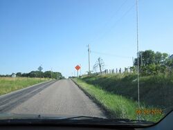
(4)
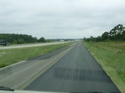
(5)


The roadway in Picture 4 should have temporary center line pavement markers or stripes. Picture 5 shows a project using half of the permanent center line stripe as the pavement marking and not place TPM until the other lane is overlaid, which is unacceptable.
- Unacceptable Examples
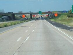
(6)
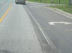
(7)
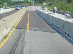
(8)


Pavement marking installation and removal should be done carefully as not to misdirect the road user. The TPM (Picture 6) were intended to move the traffic to a temporary shoulder lane.
- Note: The permanent center line should have been removed to avoid road user confusion.
Picture 7 shows a right turn lane line partially removed, care should be given to completely remove all conflicting markings in accordance with the plans and specifications. In Picture 8 shows conflicting edge lines across the bridge.
- Unacceptable Examples
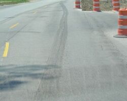
(9)
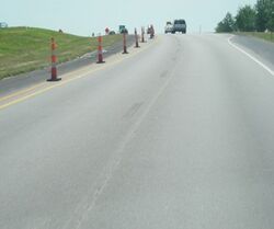
(10)
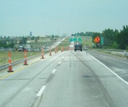
(11)
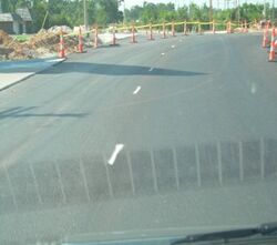
(12)


Pictures 9 - 12 are examples of pavement marking removal. Care should be taken not to scar the pavement when removing markings. Pictures 11 and 12 shows lane lines leading motorists into the channelization. The dashed line should stop at a point when the two lanes are designated to end.
616.19.2.5.2 Traffic Management
To provide adequate traffic management many tools are available which includes but not limited to the following: signs, channelizing devices, changeable and dynamic message signs, intelligent transportation systems (ITS), detours, law enforcement, flagging operation, etc.
EPG 616.13 Work Zone Capacity, Queue and Travel Delay and EPG 616.14 Work Zone Safety and Mobility Policy have additional information for traffic management policies and tools.
- Acceptable Examples
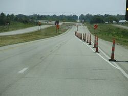
(1)
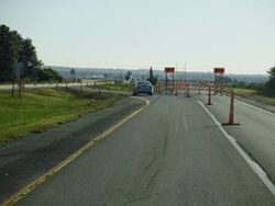
(2)
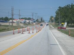
(3)


Pictures 1 - 3 are acceptable examples of traffic management. Picture 1 shows a long-term stationary work zone that is providing a well-defined merge taper with adequate striping and channelizers. Picture 2 shows a well-marked crossover. The temporary work zone in Picture 3 shows proper delineation for head to head traffic while providing access to area businesses.
- Acceptable Examples
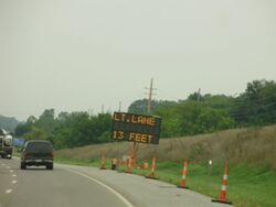
(4)
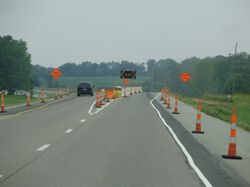
(5)
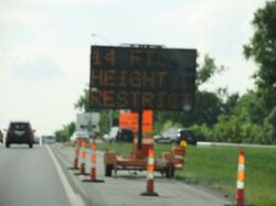
(6)


Pictures 4 and 5 are examples of providing the road user information of how wide the lanes are before entering the workzone. The CMS message provides adequate information to allow the road user to make a decision on the proper lane to use. Picture 6 is an example of height restriction for the road user.
616.19.2.5.3 Rejected Stickers for TTC Devices


REJECTED stickers, with appropriate month and year designated, may be used by MoDOT personnel to identify unacceptable temporary traffic control devices. For barricades, channelizing devices and signs, the sticker should be located on the front-, left- and lower-most retroreflective area on the device. For other devices, the sticker should be located in a conspicuous place on the device.