751.22 Prestressed Concrete I Girders
| Video |
| Concrete Girder |
Contents
- 1 751.22.1 General
- 2 751.22.2 Design
- 3 751.22.3 Details
- 3.1 751.22.3.1 Reinforcement Criteria
- 3.2 751.22.3.2 Strand Arrangements
- 3.3 751.22.3.3 Top Flange Blockout for NU Girders
- 3.4 751.22.3.4 Girder Reinforcement
- 3.5 751.22.3.5 Strands at Girder Ends
- 3.6 751.22.3.6 Camber, Haunching, and Stepping and Sloping of Top Flange
- 3.7 751.22.3.7 Closed Concrete Intermediate Diaphragms
- 3.8 751.22.3.8 Open Concrete Intermediate Diaphragms
- 3.9 751.22.3.9 Concrete End Diaphragms
- 3.10 751.22.3.10 Coil Inserts and Tie Rods
- 3.11 751.22.3.11 Steel Intermediate Diaphragms
- 3.12 751.22.3.12 Vent Holes
- 3.13 751.22.3.13 Concrete Shear Blocks
- 3.14 751.22.3.14 Miscellaneous
751.22.1 General
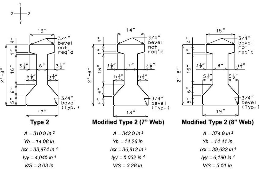
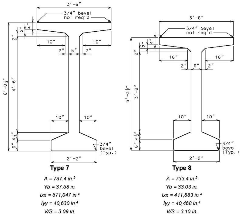
EPG 751.22 illustrates the general design procedure for prestressed concrete I girders (Type 2, 3, 4 and 6), bulb-tee girders (Type 7 and 8) and NU girders (NU 35, 43, 53, 63, 70 and 78) using AASHTO LRFD Bridge Design Specifications except as noted.
751.22.1.1 Material Properties

Increasing Girder Capacity
The following allowable modification of material properties listed in order of increasing costs may be considered if required by design.
- 1. Increase concrete strength up to 8.0 ksi (f′c = 6.5 ksi) (readily producible by fabricator)
- 2. Increase concrete strength greater than 8.0 ksi (readily producible by fabricator)
- 3. Modify geometric properties (in order of increasing costs)
- a. Increase top flange height (and overall height accordingly)
- b. Use modified Type 2, 3, 4 and 6 girders (most costly and inconvenient due to required forming bed modifications)
Class A-1 Concrete
Conventional concrete with the following compression strengths shall be used as required for I girders and bulb-tee girders.
The lowest concrete strength satisfying the demand shall be used.
The NU girders shall use conventional concrete with the following compression strength.
High strength concrete with compressive strengths up to f′c =10 ksi (f′ci = 7.0 ksi) may be used with the permission of the Structural Project Manager or Structural Liaison Engineer. High strength concrete may increase costs due to production modifications necessary to obtain the required strength.
Modulus of Elasticity
- Ec = 33,000K1wc1.5√f′c (f′c in ksi)
- where:
- K1 = correction factor for source of aggregate = 1.0 unless determined by physical testing
- wc = 0.140 + 0.001f′c (f′c in ksi)
- where:
Prestressing Strands
Prestressing strands shall be Grade 270 uncoated, low relaxation, seven-wire strands in accordance with AASHTO M 203 with the following design properties.
| Ultimate tensile strength, fpu = 270 ksi | 1/2-inch strand: diameter, dps = 0.5 in. and area, Aps = 0.153 in.2 | |
| Yield strength, fpy = 0.9fpu = 243 ksi | 0.6-inch strand: diameter, dps = 0.6 in. and area, Aps = 0.217 in.2 | |
| Maximum allowed force per strand, fpbt Aps = 30.98 kips (1/2-inch strands) fpbt Aps = 43.94 kips (0.6-inch strands) |
Modulus of elasticity, Ep = 28,500 ksi Maximum allowed stress prior to transfer, fpbt = 0.75fpu = 202.5 ksi |
Total initial prestress force equals the number of strands multiplied by the required initial prestress force per strand.
Typically, the required initial prestress force per strand is the maximum allowed force per strand.
Report on the plans the required number of strands by design and the total initial prestress force using EPG 751.50 Standard Detailing Notes H2c1.3.
Reinforcing Steel
Deformed bars shall be Grade 60 in accordance with AASHTO M 31 with the following design properties.
| Yield strength, fy = 60.0 ksi | Modulus of elasticity, Es = 29,000 ksi |
Welded wire reinforcement shall be in accordance with AASHTO M 336 with the following design properties.
| Yield strength, fy = 70.0 ksi | Modulus of elasticity, Es = 29,000 ksi |
All bars extending into slab shall be epoxy coated. Welded wired reinforcement shall not be epoxy coated.
751.22.1.2 Geometric Properties
The following sections, except those specified as modified, shall be preferred because of their familiarity to local precast plants. These sections have been entered into the beam section libraries of in-house design software. The top flange height and overall height may be increased if required but any deviation from the standard sections shown shall be discussed with Structural Project Manager or Structural Liaison Engineer. The use of the modified girders shall be discussed with Structural Project Manager or Structural Liaison Engineer.
- I Girders:


- Bulb-Tee Girders:

- NU Girders:


751.22.1.3 Typical Span Ranges
The following charts provide a general baseline for the maximum span lengths of prestressed I-girders and NU girders based off single span designs in accordance with LRFD, 9th Edition. The designs used for these charts use the maximum practical girder spacing (9’-6” for Type 2, 3 and 4 girders, approximately 11 feet to 11’-6” for all other girders shown). The charts were developed using designs that used standard materials and shapes and no debonding. Increased span lengths are possible with modification to the materials, shapes, and/or girder spacings used. Increased span lengths are also likely for continuous span bridges. See Increasing Girder Capacity section above for more information. These charts shall be used for preliminary design only.
Limitations of the Charts:
These charts only contain data on designs with a concrete compressive strength equal to 8.0ksi, this is due to a lack of sufficient data for designs using a concrete compressive strength of 6.0ksi or 7.0ksi.

| Note: | Type 7 I-Girder was not included due to there being insufficient data to report a justified range of span lengths. |

| Note: | Nu 78 Girders were excluded from this chart due to there being insufficient data to report an accurate range of span lengths. |
751.22.1.4 Span and Structure Lengths
751.22.1.4.1 Limits
Span Lengths
Designs using MoDOT standard Type 6 girders shall be limited to 105 feet maximum length to ensure stability during fabrication, shipping and erection.
No limits are set for other types of prestressed girders however the Structural Project Manager or Structural Liaison Engineer shall be consulted prior to the design of any unusually long prestressed girder.
Continuous Structure Lengths

751.22.1.4.2 Girder Length and Geometric Layout
- Tangent Bridges
- Girder lengths of exterior spans (i.e., end spans) and interior spans shall be computed using the requirements shown below.

- The layout length for single span shall be measured from centerline of bearing to centerline of bearing. If the difference between layout length of the end span and interior span is within one foot, then layout length should be adjusted if possible so the girder lengths are equal for end span and interior span.
- (1) Minimum dimension from edge of bearing pad to end of girder equals one inch.
- (2) Design layout lengths are horizontal lengths. Girder lengths should be adjusted according to grade and shall be specified to the nearest 1/8 inch.
- (3) For large skews, end bent beam caps may need to be larger to provide edge distance.
- (4) Horizontal distance along certerline of girder.
- (5) = 1ʺ (minimum) + ½ bearing pad length which equals:
- 5ʺ (minimum) for I-girders and squared-end adjacent beams,
- 3 ½ʺ (minimum) for NU girders and spread beams with squared ends,
- 3⅝ʺ (minimum) for skewed-end spread beams, 3½ʺSEC(15°).
- (5) = 1ʺ (minimum) + ½ bearing pad length which equals:
- Curved Bridges
- Layout of any curved structure may be done using any coordinate geometry programs available. To layout the bridge, use the following steps:
- Start out by laying in the centerline (CL) of the survey curve.
- Locate the tie point of the bridge. This point will usually be on the CL of the survey curve but may be on a baseline which is offset a certain distance to the CL of the survey curve.
- A second tie point may be required if the skew is not measured to the CL of roadway at the bridge tie point. If this is the case, establish the tie point at the specified station and plot the skew line at the required angle.
- Next, on the centerline of structure or baseline curve, locate the station of the CL of bent for each intermediate bent and the fill face for the end bents. Once these points are located, plot lines through these stations parallel to skew line. Normally the layout file will specify that all bents are parallel to the skew line; however, there may be times when the bents are radial or have varying skews.
- When locating the stations in the preceding step, the distance between CL of intermediate bents are exactly the layout lengths specified on the file. However, the end spans need to follow the procedure for calculating length set forth in Tangent Bridges.
- When the CL of the intermediate bents and the fill face lines have been added, chords should be drawn connecting these points sequentially. For example, if you have a three-span bridge, chords should be drawn from the fill face of bent 1 to CL of bent 2, CL bent 2 to CL bent 3, and CL bent 3 to fill face bent 4.
- When all the chords are in, offset each girder in each span parallel to this chord. The perpendicular distance between girders will be the same for all spans, but the skew distance between girders along the bent will vary from bent to bent depending on the skew to the CL at that point. The designer needs to be aware of the fact that at an intermediate bent the distance between bearings on the approaching and leaving span sides will be different distances. These bearings will not line up across the bent and will actually diverge more the farther away they are from the CL of the survey.
- When establishing the CL of bearing points, the designer needs to allow for a minimum of seven (7) inches between ends of girders at the bents while keeping in mind that the girders will be offset and at different skews. If the offset is greater than half the girder bottom flange width, see Structural Project Manager. The distance from the end of girder to CL of bearing point should be half of the bearing length plus one inch minimum clearance. Once the distance for CL bent to CL of bearing is calculated, the designer should offset lines by that dimension on either side of the CL of bent. These lines will then be intersected with each of the girder lines to create the bearing points on each bent.
- Between the bearing points at the ends of the girders, quarter points or tenth points need to be established, depending on the girder span. These points will be used in calculating the haunch and bottom of slab elevations for the bridge deck.
- The bridge deck and barrier or railing can be laid in by offsetting the centerline of roadway to each side by the proper distance. Curves should be laid in to designate both the inside and outside edges of the barrier or railing. These will later be useful in laying in the wings and end bents.
- After the outside edge of slab curves are plotted, the curve offsets need to be found. The intersection points of the outside edge of slab and the centerline of each bent or fill face can be connected with chords. The distance between these chords and their partner curves need to be calculated at five-foot intervals beginning at the center point of each chord.
- Joints are placed in the barrier or railing at each bent. These joints are placed perpendicular to the centerline of the roadway through the intersection point of the centerline bent and the inside edge of barrier or railing.
- Wing layout length is given on the profile sheets in the layout file. An arc should be struck so as to intersect the inside edge of barrier or railing the specified length from a point at the intersection of the fill face and the inside edge of barrier or railing. This point will mark the end of the wing which is perpendicular to the centerline of the roadway.
- The vertical curve information needs to be added so a program can calculate the elevations at the desired stations. After this is done, the designer can request any of the following information which will be needed:
- Stations and elevations of all points
- Offset distances to the chords
- Lengths of girders
- Distances between bearings
- Angles between girders and each bent
- Lengths of bents
- Lengths of barrier or railing between joints
- Minimum vertical clearance.
751.22.1.4.3 Coping of Girder Ends
Non-Integral end bents with skews greater than 40 degrees shall always have girder ends coped. Skews less than 40 degrees shall have girder ends coped on case by case basis. It is preferable to not cope across the web.
Check clearance from fill face of integral end bents to bottom flanges of NU girders. Maintain 3-inch minimum clearance. Coping may be permitted with approval of the Structural Project Manager or Structural Liaison Engineer.

751.22.1.5 Constant and Varied Joint Filler Loads
Varied joint filler load
Girders shall be first designed assuming that the contractor will vary the joint filler supporting the panels on the girder flange. This assumption will maintain the minimum slab/panel combination thickness of 8 1/2 inches, and will eliminate the possibility of increased load due to varying slab thickness.
Constant joint filler load
With the girder designed and the camber and haunching dimensions calculated, the girder should be checked assuming the contractor will use a constant 1” joint filler. This will cause the slab thickness to vary due to camber of the girder, increasing load. This additional load shall be placed as a concentrated load at 1/8 point from each end of the girder.
An example of how this concentrated load could be calculated is shown as follows:
- Load
- Determine the concentrated load* to girders by distributing w transversely across the girders. If the minimum haunch is greater than 1” joint filler, the additional haunch shall be included in the slab thickness as a uniform load. If the use of these loads causes the girder design to change, it shall be the responsibility of the designer to determine if the camber and haunching should be recalculated.

This load shall be positioned at the 1/8 point from centerline of bearing pad.

The girder and bearing designs should be checked for the constant joint filler option and constant joint filler load. However, camber, haunching and beam seat elevations shown on the plans should be based on the variable joint filler option.

751.22.2 Design
751.22.2.1 Load Combinations
In general, each component shall satisfy the following equation:


Where:
| = Total factored force effect | |
| = Force effect | |
| = Load modifier | |
| = Load factor | |
| = Resistance factor | |
| = Nominal resistance | |
| = Factored resistance |


- Limit States
The following limit states shall be considered for P/S Girder design:
- SERVICE I - for compressive stress
- SERVICE III - for tensile stress
- STRENGTH I
See LRFD Table 3.4.1-1 for Loads and Load Factors applied at each given limit state.
- Resistance factors,
STRENGTH limit states, see LRFD Article 6.5.4.2 & 5.5.4.2
For all other limit states, = 1.00
See EPG 751.2.3.1 Load Modifiers.
751.22.2.2 Prestressing Strands
Transfer Length of Prestressing Strands
The prestressing force may be assumed to vary linearly from zero at the point where bonding commences to a maximum at the transfer length. The transfer length may be taken as 60 times the strand diameter.
Development Length of Prestressing Strands
The development length for prestressing strands shall be taken as:

Where: = Nominal diameter of strand, (in.) = Average stress in prestressing strand at the time for which the nominal resistance of the girder is required, (ksi)


Stress limits for prestressing strands
Strand stress at service limit state shall not exceed the following:
At jacking:
- ksi
- (For typical girders and fabrication economy, )


At service limit state after all losses:
- ksi

Where:
| = Stress in prestressing strand at jacking, (ksi) | |
| = Effective stress of strand after all losses, (ksi) | |
| = Yield strength of strand, (ksi) | |
| = Ultimate tensile strength of strand, (ksi) |


Prestress Losses
Refined estimates of time-dependent losses are used, based on AASHTO LRFD Article 5.9.3.4, as opposed to approximate lump sum estimate of losses in AASHTO LRFD Article 5.9.3.3.
The prestress losses shall be calculated to investigate concrete stresses at two different stages.
- Temporary stresses immediately after transfer:
- Final stresses
SERVICE I and SERVICE III Limit states shall be investigated at each stage.
Harped Strands
Harped strands, although they add to the shear strength of the girder, are primarily used to keep the girder stresses (both top and bottom) within allowable limits while developing the full capacity of the girder at midspan.
Harped strands should be held down at points of 0.4 of the distance from each end of the girder. Distances along girder to hold-down devices and between hold-down devices should be reported on the plans to the nearest inch. Per Sec 1029, precaster may position hold-down devices +/- 6 in. longitudinally from position shown on the plans.

The jacking force applied to prestress strands produces an excessive vertical uplift in short spans on tall girders resulting in failure of harped strand hold-downs. The allowable limits for hold-downs are as follows:
- 5 kip/strand
- 10 kip/bolt
- 42 kip/hold-down

If necessary lower harped strand end location to meet criteria or use straight strands only. Investigate the possibility of using all straight strands when strength check of a hold-down device exceeds allowable.
Straight Strands.
Short spans (<40 ft.) are to use straight strands only for all girders greater than 2'-8" tall. Use at least two straight strands at the top of the girder when straight strands are used. Where straight strands only will not work a single hold-down point may be used. Note: A single point hold-down has twice the uplift force.
Strand Arrangement Optimizing
Using all straight strands for girder lengths less than 70 feet shall be investigated for Type 6, 7 and 8 girders and all NU girders in order to reduce risk of strand or hold-down breakage, increase safety by reducing risk of injury during fabrication and reduce cost.
Consider using the same section for all spans. This permits the use of shorter girders in the casting bed with longer girders, even if straight strands are needed, in the top flanges of the girders. They can be placed at either end of the bed and still optimize the usage of the bed.
Consider using the same number of draped strands for all spans and debond where needed. Strand patterns should be similar between long and short spans. For example, the designer should not use a single column of draped strands on the short spans and two columns of draped strands on the long spans. This will prevent optimization of the bed.
When using straight strands in the top flange of NU Girders and harped strands, lower (drop) the harped strand end locations and vertically align straight strands directly over harped strands to facilitate top flange blockout fabrication by removing interference created between straight strands placed to the outside of the harped strands and the flange blockout forms. If for any reason this is not possible, then place straight strands to the outside of the harped strands.
Debonding Strands
Debonding at girder ends may be used to reduce concrete compressive forces and shall be used if required to reduce the prestress force at transfer to meet bursting/splitting requirements. Debonding strands shall be avoided at girder ends located underneath expansion joints.
In all debonding operations the prestressing forces must be in such a manner as to prevent any sudden or shock loading.
Debonding a strand consists of wrapping the unnecessary strand(s) with a polyethylene plastic sleeve that prevents interaction of the strand with the concrete during casting and release which prevents any prestress force transfer.
751.22.2.3 Flexure
Flexure capacity of girders shall be determined as the following.
Flexural resistance at strength limit state

Where:
| = | Flexural resistance | |
| = | Nominal flexural resistance | |
| = | Total factored moment from Strength I load combination | |
| = | Flexural resistance factor as calculated in LRFD 5.5.4.2 |


Negative moment reinforcement design
P/S I-girder shall be designed as a reinforced concrete section at regions of negative flexures (i.e., negative moments).
At least one-third of the total tensile reinforcement provided for negative moment at the support shall have an embedment length beyond the point of inflection not less than the specified development length of the bars used.
Slab longitudinal reinforcement that contributes to making the precast beam continuous over an intermediate bent shall be anchored in regions of the slab that can be shown to be crack-free at strength limit states. This reinforcement anchorage shall be staggered. Regular longitudinal slab reinforcement may be utilized as part of the total longitudinal reinforcement required.
Effective Slab Thickness
An effective slab thickness shall be used for design by deducting from the actual slab thickness a 1” integral, sacrificial wearing surface.
Design A1 reinforcement in the top flange
The A1 reinforcement shall resist the tensile force in a cracked section computed on the basis of an uncracked section.
For I girders and bulb-tee girders, A1 reinforcement shall consist of deformed bars (minimum #5 for Type 2, 3 and 4 and minimum #6 for Type 6, 7 and 8).
For NU girders, A1 reinforcement shall consist of the four 3/8-inch diameter reinforcement support strands with deformed bars added only as needed. The WWR in the top flange shall not be used for A1 reinforcement because there is insufficient clearance to splice the WWR.
Reinforcement shall be designed and spliced using f’ci in accordance with EPG 751.5.9.2.8 Development and Lap Splices.
Required steel area is equal to:

Where:
| = , allowable tensile stress of mild steel, (ksi) | |
| = Resultant of total tensile force computed on the basis of an uncracked section, (kips) |


Limits for reinforcement
The following criteria shall be considered only at composite stage.
Minimum amount of prestressed and non-prestressed tensile reinforcement shall be so that the factored flexural resistance, Mr, is at least equal to the lesser of:
- 1) Mcr LRFD Eq. 5.6.3.3-1
- 2) 1.33Mu
Where:
| Mcr | = | Cracking moment, (kip-in.) |
| Mu | = | Total factored moment from Strength I load combination, (kip-in.) |
751.22.2.4 Shear
Shear capacity of girders shall be checked along girder length and girder-slab interface.
Shear resistance at strength limit state

Where:
| = | Shear resistance | |
| = | Nominal shear resistance | |
| = | Total factored shear from Strength I load combination | |
| = | Shear resistance factor |


Nominal shear resistance
The nominal shear resistance, , shall be lesser of:
- , or


Where:


Where:
| = | Nominal concrete shear resistance, (kips) | |
| = | Nominal shear reinforcement resistance, (kips) | |
| = | Component of prestressing force in the direction of shear force, (kips) | |
| = | Thickness of web, (in.) | |
| = | Effective shear depth taken as the distance measured perpendicular to the neutral axis, between the resultants of tensile and compressive forces due to flexure, (in.) | |
| = | Spacing of shear reinforcement, (in.) | |
| = | Factor indicating ability of diagonally cracked concrete to transmit tension | |
| = | Angle of inclination of diagonal compressive stress, (degree) | |
| = | 90.0, Angle of inclination of shear reinforcement to a longitudinal axis, (degree) | |
| = | Area of shear reinforcement, (in.2) | |
| = | Minimum yield strength of tension shear reinforcement, (ksi) |


Design sections near supports
Where a reaction force in the direction of the applied shear introduces compression into the end region of girder, the location of the critical section for shear is measured from the internal face of support a distance, dv. Otherwise, the design section shall be taken at the internal face of the support.
Where:
= effective shear depth taken as the distance, measured perpendicular to the neutral axis, between the resultants of the tensile and compressive forces due to flexure; it need not be taken to be less than the greater of 0.9de and 0.72h.
Girder regions requiring shear reinforcement
Girder shear reinforcement, usually consisting of stirrups, shall be provided where:

Where:
| = | Factored shear force from Strength I load combination, (kips) | |
| = | Nominal concrete shear resistance, (kips) | |
| = | Component of prestressing force in the direction of shear force, (kips) | |
| = = |
Shear resistance factor
0.9 for normal weight concrete |
Shear Reinforcement Limits
Minimum reinforcement
Area of shear reinforcement shall not be less than:

Where:
| = | Area of shear reinforcement, (in.2) | |
| = | Thickness of web, (in.) | |
| = | Spacing of shear reinforcement, (in.) | |
| = | Final concrete compressive strength, (ksi) |

Maximum spacing
Maximum spacing of shear reinforcement shall be determined as:
If , then


If , then


Where:
| = | Effective shear depth taken as the distance measured perpendicular to the neutral axis, between the resultants of tensile and compressive forces due to flexure, (in.) | |
| = | Shear stress on concrete, (ksi) | |
| = | Maximum spacing of shear reinforcement, (in.) |


Shear stress on concrete shall be determined as:


Where:
| = | Shear stress on concrete, (ksi) | |
| = | Factored shear from Strength I load combination, (kips) | |
| = = |
Shear resistance factor
0.9 for normal weight concrete | |
| = | Thickness of web, (in.) | |
| = | Component of prestressing force in the direction of shear force, (kips) | |
| = | Effective shear depth taken as the distance measured perpendicular to the neutral axis, between the resultants of tensile and compressive forces due to flexure, (in.) | |
| = | ||
| = | Distance from extreme compression fiber to the centroid of tensile force in the tensile reinforcement, (in.) | |
| = | Total height of girder including slab thickness, (in.) |


Girder-Slab Interface
The horizontal shear between the girder and slab shall be determined as specified in LRFD 5.7.4.4. The nominal horizontal shear resistance of the interface plane shall be taken as specified in LRFD 5.7.4.3. Minimum interface shear reinforcement shall be provided as specified in LRFD 5.7.4.2. The parameters used in determining the nominal horizontal shear resistance shall be taken as specified for a “cast-in-place concrete slab on clean concrete girder surfaces, free of laitance with surface roughened to an amplitude of 0.25 inch.”
The interface shear shall be resisted by extending and anchoring the vertical shear reinforcement into the slab. If the resistance provided by extending the vertical shear reinforcement is inadequate then, in lieu of increasing shear reinforcement, additional U bars may be provided as shown for a Type 7 girder in EPG 751.22.3.4 Girder Reinforcement.
For NU girders and spread beams the top flange shall be debonded at the edges using a smooth finish and an applied bond breaker to help aid with future deck removal and minimize stress concerns with the thin flange of the NU girders. The debonded regions shall not be included when determining the nominal horizontal shear resistance. The minimum debonded width shown below may be increased in lieu of adding additional U bars in order to reduce the minimum interface shear reinforcement.

The debonding regions shall be indicated on the plans by specifying the required smooth finish and applied bond breaker in the dimensions detail on the beam or girder sheet. Omit underlined portion of footnote (1) if prestressed panels are not used.
Similarly, for all other prestressed girders and beams, the joint filler width supporting precast panels shall be considered debonded and excluded when determining the interface resistance.
751.22.2.5 Pretensioned Anchorage Zones
(LRFD 5.9.4.4)
Bursting Resistance (AASHTO Splitting Resistance)
The bursting resistance of anchorage zones provided by vertical reinforcement (i.e., B2 bars and the D31 wires of WWR6) in the ends of prestressed girders at the service limit state shall be taken as:

The required vertical reinforcement shall be provided within the following end regions:
- I Girders, NU 35, 43 & 53 Girders:
- - Within h/3, in accordance with research by Davis, Buckner and Ozyildirimon (Dunkman et al. 2009).
- Bulb-Tee Girders and NU 63, 70 & 78 Girders:
- - Within h/4
- I Girders, NU 35, 43 & 53 Girders:
Where:
| = | Stress in mild steel not exceeding 20 ksi | |
| = | Total area of vertical reinforcement located within the specified minimum distance from the end of the girder where h equals the overall depth of precast member as shown below. | |
| = | Prestressing force immediately prior to transfer |


(Bursting zone or reinforcement may differ for other girder types)
The number of strands bonded in the anchorage zone is limited by the standard bursting reinforcement of EPG 751.22.3.4.3 Anchorage Zone Reinforcement and the 20 ksi resistance stress limit.
| I Girders & Bulb-Tee Girdersa | NU Girders | |||||||||||
|---|---|---|---|---|---|---|---|---|---|---|---|---|
| Type | h/3 or h/4 (in.) |
#6-B2 Pairs |
As (in.2) |
Ns | Type | h/3 or h/4 (in.) |
D31 Pairs |
As (in.2) |
Ns | |||
| (0.5") | (0.6") | (0.5") | (0.6") | |||||||||
| Type 2 | 10.67 | 3.0 | 2.65 | 20 | 20 | NU 35 | 11.81 | 5.5 | 3.41 | 54 | 38 | |
| Type 3 | 13.00 | 4.0 | 3.53 | 24 | 24 | NU 43 | 14.44 | 7.0 | 4.34 | 62a | 48 | |
| Type 4 | 15.00 | 4.0 | 3.53 | 32 | 32 | NU 53 | 17.72 | 8.5 | 5.27 | 62a | 52b | |
| Type 6 | 18.00 | 4.0 | 3.53 | 38 | 38 | NU 63 | 15.75 | 7.5 | 4.65 | 62a | 52 | |
| Type 7 | 18.13 | 4.0 | 3.53 | 40 | 40 | NU 70 | 17.72 | 8.5 | 5.27 | 62a | 58 | |
| Type 8 | 15.88 | 4.0 | 3.53 | 40 | 40 | NU 78 | 19.69 | 9.0 | 5.58 | 62a | 62a | |
| Area of one #6-B2 bar = 0.4418 in.2 | Area of one D31 wire = 0.31 in.2 | |||||||||||
| a Maximum number capped by strand arrangements shown in this article and on the Bridge Standard Drawings. | ||||||||||||
| b Maximum number capped not to exceed the maximum allowed for the NU 63 girder. | ||||||||||||
- Ns ≤ As /As(req) (Rounded down to nearest even number for the purpose of symmetry.)
- Where:
- As(req) = Required bursting reinforcement for one prestressing strand.
- = 0.04fpbtAps /fs
- = (0.04)(202.5 ksi)(0.153 in.2)/(20 ksi) = 0.0620 in.2 (1/2-inch strand)
- = (0.04)(202.5 ksi)(0.217 in.2)/(20 ksi) = 0.0879 in.2 (0.6-inch strand)
- As(req) = Required bursting reinforcement for one prestressing strand.
Confinement reinforcement
Confinement reinforcement (i.e., D1 bars or G1 bars spaced with WWR4) shown in the figure above shall be placed to confine the prestressing strands in the bottom flange for a minimum distance of 1.5d from the end of beam.
The reinforcement shall not be less than #3 deformed bar, with spacing not exceeding 6.0 inches and shaped to enclose the strands.
The use of D1 bars shall be extended for the full length of I girders, bulb-tee girders and alternate bar-reinforced NU girders.
The use of G1 bars at 6-inch spacing shall be extended for the first 10 feet and then at 12-inch spacing for the remaining length of welded wire-reinforced NU girders.
751.22.2.6 Deformations
Criteria for deflection
For investigating maximum absolute deflection, all design lanes shall be loaded, and all supporting components should be assumed to deflect equally.
For composite design, the design cross-section should include the entire width of the roadway and the structurally continuous portions of railings, sidewalks, and median barriers. Note that barrier and railing are usually discontinuous over the bents. For skewed bridges, a right cross-section may be used.
Service I load combination shall be used. Dynamic load allowance shall be applied.
See EPG 751.2.4.2 Live Load Deflection Limits.
Calculation of deflection and camber
Deflection and camber calculations shall consider all internal loads (i.e., prestressing, concrete creep, and shrinkage) and external loads such as dead loads and live loads.
Camber is an upward displacement caused by moment due to prestressing forces. Deflection is a downward displacement due to external loads. Therefore, both camber and deflection shall be considered in making an appropriate adjustment for final profile grade on the bridge.
Initial camber at transfer at midspan
Total initial camber at transfer due to self-weight of girder and prestressing forces shall be determined as:

Where:
| = Initial camber at transfer | |
| = Deflection due to self-weight of girder | |
| = Camber due to prestressing straight strands | |
| = Camber due to prestressing harped strands |


Note: Positive and negative values indicate downward and upward displacements, respectively.
Camber at midspan after strand release (Estimated at 7 days)
Theoretical camber of girder after strand release due to self-weight of girder and prestressing forces shall be determined at 7 days as:

Where:
| = Camber at 7 days after strand release with creep | |
| = Time - dependent camber due to creep at 7 days |


Note: Camber is calculated 7 days after strand release to allow sufficient time for inspection. See EPG 1029 Fabricating Prestressed Concrete Members for Bridges.
Camber at midspan after erection (Estimated at 90 days)
Theoretical camber of prestressed girders after erection are estimated at 90 days for typical projects. While some projects may require prestressed girders to be erected in less than 90 days in order to meet fast construction timelines or emergency repair requirements, using less than 90 days (i.e, 45 or 60) would potentially result in lower camber estimates and higher beam seat elevations. The cost risk is believed to be greater for underestimating the camber since it may require an increase in final grade. Due to the risk in underestimating camber and the multitude of variables that affect the actual camber (variability in predicting concrete modulus of elasticity, coarse aggregate effect on initial concrete modulus of elasticity, actual concrete strength, differential temperature at strand release, etc…) the 90 day estimate should be adequate for most projects.
Theoretical camber of girder after erection due to self-weight of girder and prestressing forces shall be determined at 90 days as:

Where:
| = Camber at 90 days after strand release with creep | |
| = Time - dependent camber due to creep at 90 days |


Final camber at midspan after slab is poured
Total deformation after slab is poured can be determined as the sum of theoretical camber of girder after erection (90 days) and deflections due to slab and concentrated loads (haunch, diaphragms, etc.) before composite action between slab and girder.

Where:
| = | Final camber after slab is poured | |
| = | Deflection due to weight of slab | |
| = | Deflection due to concentrated loads (haunch, diaphragms, etc.) |


Final camber along span length
Deformations along the span length can be approximately determined as a product of final camber at midspan times correction factors.
| = | 0.3140 at span fraction of 0.10 | |
| = | 0.5930 at span fraction of 0.20 | |
| = | 0.7125 at span fraction of 0.25 | |
| = | 0.8130 at span fraction of 0.30 | |
| = | 0.9520 at span fraction of 0.40 | |
| = | 1.0000 at span fraction of 0.50 |


Calculation of camber (upward) using transformed properties
Camber at midspan due to strand forces is determined by the following:
For straight strands (groups determined by debonding lengths),

Where:


Where:
| = Total prestressing force of straight strand group just prior to transfer, (kips) | |
| = Distance between centerlines of bearing pads, (in.) | |
| = Debond length of straight strand group from end of girder, (in.) | |
| = Initial concrete modulus of elasticity based on , (ksi) | |
| = Moment of inertia of transformed non-composite section computed based on , (in.4) | |
| = Eccentricity between centroid of straight strand group (CSS) and center of gravity of transformed non-composite section (CGB) as shown in Figure below, (in.) | |
| = Prestressing force in the strand just prior to transfer, (ksi) | |
| = Summation of the time dependent losses (7 or 90 day). Losses include relaxation, creep and shrinkage, but exclude elastic shortening. |


Gross properties may be used to calculate losses and is consistent with AASHTO LRFD 5.9.3.4.
For two-point harped strands,

Where:


Where:
| = Total prestressing force of harped strands just prior to transfer, (kips) | |
| = Length between harped points, (in.) | |
| = Eccentricity between centroid of harped strands (CHS) and center of gravity of transformed non-composite section (CGB) at midspan as shown in Figure below, (in.) | |
| = Eccentricity between centroid of harped strands (CHS) and center of gravity of transformed non-composite section (CGB) at the end of girder as shown in Figure below, (in.) |


Calculations of deflections (downward)
Deflections at midspan due to dead loads are determined as the following: For self-weight of girder,

Where:
- = Uniform load due to self-weight of girder, (kip/in.)

For self-weight of slab,

Where:
- = Uniform load due to self-weight of slab, (kip/in.)

- = Final concrete modulus of elasticity based on f'c, (ksi)

- = Moment of inertia of transformed non-composite section based on Ec, (in.4)

Weight of additional slab haunch may be treated as uniform or concentrated load as appropriate. Diaphragm weight should be treated as concentrated load.
For one concentrated load at midspan,

For two equal concentrated loads,

Where:
| = Concentrated load due to diaphragm and/or additional slab haunch, (kips) | |
| = Distance from the centerline of bearing pad to the applied load, P, (in.) |


| Creep coefficient | LRFD 5.4.2.3.2 |
Research has indicated that high strength concrete (HSC) undergoes less ultimate creep and shrinkage than conventional concrete.
Creep is a time-dependent phenomenon in which deformation increases under a constant stress. Creep coefficient is a ratio of creep strain over elastic strain, and it can be estimated as follows:
| = | |
| = | |
| = | |
| = | |
| = |


![{\displaystyle \,t/{\Big [}{\frac {12\ (100-4f'_{ci})}{f'_{ci}+20}}+t{\Big ]}}](https://wikimedia.org/api/rest_v1/media/math/render/svg/56e05011c1912e2b4f5e5b02777ec45c6c3e791f)
Where:
| = Creep coefficient. | |
| = 70, Average annual ambient relative humidity | |
| = Maturity of concrete, (days) Use 7 days for camber design after strand release Use 90 days for camber design after erection | |
| = Age of concrete when a load is initially applied, (days) Use 0.75 days for camber design. | |
| = Volume-to-surface area ratio, (in.) | |
| = Initial girder concrete compressive strength, (ksi) |


751.22.2.7 Dowel Bars

| PART ELEVATION (FIXED BENT) |
SECTION A-A |
- Dowel bars shall be used for all fixed intermediate bents under prestressed superstructures. Generally, for typical bridges that require seismic details only (strength limit states), shear resistance from shear key is not considered.
Dowel bars connect standard concrete diaphragms and beams on concrete girder bridges (standard fixed diaphragms are those with beam stirrups NOT extending up into the diaphragm). For a calculated seismic vertical reaction or an anticipated foundation settlement resulting in a net tensile reaction, use the development length of dowel bars into beam and into diaphragm based on dowel bar size. If the dowel bars are not exposed to net tension a 15-inch embedment shall be used regardless of bar size. Dowel bars size and spacing shall be determined by shear design of the bars. (Minimum #6 Bars @ 12" cts.). Dowel bars should be designed for a minimum horizontal force equal to 25% of the maximum dead load applied to the bearing. Live load is ignored in horizontal force computation.
- The number of dowels must also fit into the space available on the key:
- min. bar size = #6; max. bar size = #11
- min. spacing = 6"; max. spacing = 12"
- min. end distance = 3"; max. end distance = 6" (≤ half the spacing)
For seismic details only (strength limit states)
Horizontal factored shear force, in kips

For expansion bearings, transverse FT = 0.25(DL) & longitudinal FL = 0.
- Where DL = unfactored dead load reaction at the bent, kips
For fixed bearings, Transverse FT = 0.25(DL) and Longitudinal FL = (0.25)(segment weight) at bent.
- Segment weight includes the full width of superstructure and should be distributed appropriately among fixed bents.
For complete seismic analysis
Dowel bar designs must meet requirements for strength limit states from above as well as seismic force demand from seismic analysis.
- At Intermediate bent,

- where:
- FH = horizontal seismic force per bent, kips
- If columns are designed for plastic hinging, use the plastic hinging shear.
- ∑VL = summation of top of column longitudinal shears at the bent
- ∑VT = summation of top of column transverse shears at the bent

- Pu = Horizontal factored shear force per dowel bar, kips
- nd = number of dowel bars
Shear Resistance
Factored shear force shall be less than or equal to the nominal shear resistance.
- Pu ≤ ∅s x Rn
- where:
- ∅s = 0.75 resistance for seismic details only (strength limit states) and 1.0 for complete seismic analysis
- Nominal shear resistance of the dowel bar, Rn = 0.625 AbFub, kips
- Note: Since there is no reduced areas as seen in bolts and there is no reduction for bolted connection length, use 0.625 instead of 0.5.
- Ab = = area of the dowel bar, square inches
- Fub = minimum tensile strength of the dowel bar, ksi
- Fub = 80 ksi for Grade 60
- D = diameter of the dowel bar, inch

Tensile Resistance
Factored tensile force shall be less than or equal to the nominal tensile resistance.
- T = the maximum seismic tensile (uplift) force (DL ± EQ) from the seismic analysis, kips. If (DL+EQ) and (DL-EQ) are both compressive, then there is no need to design the dowel for tensile force.

- where:
- ∅t= 0.8 resistance factor for seismic details only (strength limit states) and 1.0 for complete seismic analysis
- nd = the number of dowel bars
- Nominal tensile resistance of the dowel bar, Tn = AbFub Kips
- Note: Since there is no pretension or reduced areas as seen for bolts, the 0.76 factor is not warranted.
- Ab = area of the dowel bar, square inches
- Fub = minimum tensile strength of the dowel bar, ksi
- Fub = 80 ksi for Grade 60
Combined Tension and Shear Resistance
The resistance of dowel bars for combined tension and shear force shall be determined in accordance with LRFD 6.13.2.11.
- Note: Since there is no pretension or reduced areas as seen for bolts, the 0.76 factor is not warranted.
- If , then Tn = AbFub
- Otherwise
- Otherwise

![{\displaystyle T_{n}=A_{b}F_{ub}{\Big [}1-{\Big (}{\frac {p_{u}}{\emptyset _{s}R_{n}}}{\Big )}^{2}{\Big ]}^{0.5}}](https://wikimedia.org/api/rest_v1/media/math/render/svg/90f1bfd4ac447d5cdfab92304126a587d0061369)
751.22.3 Details
751.22.3.1 Reinforcement Criteria
Minimum Concrete Cover
- 2.0" (Min.) to centerline of strands
- 1.0" for stirrups
Minimum Bend Diameter for Stirrups
- #3 through #5 bars = 4.0 x Nominal Bar Diameter.
- Deformed wire larger than D6 = 4.0 x Nominal Wire Diameter
Minimum Spacing of Reinforcement Bars and Wires
For precast concrete, the clear distance between parallel bars in a layer shall not be lesser than:
- Nominal Bar Diameter or Nominal Wire Diameter
- 1.33 x Maximum Aggregate Size
- 1.0"
Minimum Spacing of Prestressing Strands
Spacing between each pretressing strand shall not be less than the larger of:
- A clear distance of 1.33 x Maximum Aggregate Size
- Center-to-center spacing of 2" for 0.6" strand diameter
- Center-to-center spacing of 1.75" for 0.5" strand diameter
751.22.3.2 Strand Arrangements
Designers shall first attempt to use one of the strand arrangements specified in EPG 751.22.3.2.1 through EPG 751.22.3.2.5. The strand arrangement number shall be specified in the design. Bridge standard drawings for prestressed I-girders include strand details for each of these arrangements, by number, in the reference files for quick insertion by the technician.
For Group 1 arrangements, all strands in the center two columns are harped. For Group 2 arrangements, the bottom two center strands are straight (two less draped strands). Group 2 arrangements are not provided in diagrams below for Type 6, 7 and 8 girders, but may be derived similarly to how specified for the smaller girders.
Designers shall include an equivalent detail in the design computations when strand arrangements other than those shown are required.
The use of all straight strands (none harped) may be considered when strength check of a hold-down device exceeds allowable.
How Strand Arrangements are Detailed from Tables
- 1. For strand locations at mid-span (centerline of girder): Find the “#” designation that corresponds with the number of total strands (T) needed. The strands are to be placed at locations labeled up to and including that number. Example: For 14 total strands, the strands will be placed at all locations labeled 8 thru 14 and are designated as arrangement #14. (See Fig. 751.22.3.2.)
- 2. For harped strand locations at end of girder: Harped strands will be placed at locations labeled up to and including the number in the “H” column. Example: For 6 harped strands, the strands will be placed at all locations labeled 2 thru 6. (See Fig. 751.22.3.2.)
 |
Where: |
| # = Strand Arrangement Number T = Total Number of Strands H = Number of Harped Strands S = Number of Straight Strands |
751.22.3.2.1 Type 2 Girder

See EPG 751.3.2.6 for guidance notes (1) and (2).
751.22.3.2.2 Type 3 Girder

See EPG 751.3.2.6 for guidance notes (1) and (2).
751.22.3.2.3 Type 4 Girder

See EPG 751.3.2.6 for guidance notes (1) and (2).
751.22.3.2.4 Type 6 Girder

See EPG 751.3.2.6 for guidance notes (1) and (2).
751.22.3.2.5 Type 7 and 8 (Bulb-Tee) Girders

See EPG 751.3.2.6 for guidance notes (1) and (2).
751.22.3.2.6 NU Girders

Strand arrangements shall start at the bottom row and then move up for the most efficient design.
| (1) | Strands shall be placed on outer edge to help place confinement steel. |
| (2) | If possible, strands shall not be placed at the specified location due to the conflict with B1 and B2 bars. Harped strands at this location are less problematic since this conflict only occurs between the hold-down devices where the B1 bars are spaced farther apart. If straight strands are required below the harped strands the designer shall first attempt to locate these straight strands in the second row. The use of the strands at the specified location shall be discussed with Structural Project Manager or Structural Liaison Engineer. |
751.22.3.3 Top Flange Blockout for NU Girders
| No Skew |
 |
| >0° to 7° LA Skew (Mirror for right advanced.) |
 |
| >7° to 14° LA Skew (Mirror for right advanced.) |
 |
| >14° to 60° LA Skew (Mirror for right advanced.) |
 |
Choose one of the above four details for the top flange blockout detail and follow the provided detailing guidance.
Blockout shall be dimensioned along the girder to 1 1/2 inches inside the face of the diaphragm and adjusted for any girder tilt.
The left advanced details shown may be used for right advanced bridges. The mirror note may be removed if left advanced.
Revise bent references as required and specify the bent number if blockout varies by bent.
The skew angle value need not be shown for tangent bridges. Consult SPM or Liaison on replacing "skew angle" with actual value for curved bridges.
Revised titles for non-integral end bents (exterior girder at end bent will be same detail as at intermediate bent).
| Skew | X Eq. Spa. |
X #4-G6 |
Bar Lengths |
|---|---|---|---|
| >14° to 21° | 3 | 2 | G3 bar = G5 bar = For skews >7° to 14°: G6 bar = For skews >14° to 60°: report length of G6 bars as “Varies” |
| >21° to 27° | 4 | 3 | |
| >27° to 32° | 5 | 4 | |
| >32° to 37° | 6 | 5 | |
| >37° to 42° | 7 | 6 | |
| >42° to 46° | 8 | 7 | |
| >46° to 49° | 9 | 8 | |
| >49° to 52° | 10 | 9 | |
| >52° to 55° | 11 | 10 | |
| >55° to 57° | 12 | 11 | |
| >57° to 60° | 13 | 12 |


751.22.3.4 Girder Reinforcement
751.22.3.4.1 Reinforcing Steel Details
I Girders and Bulb-Tee Girders
See Bridge Standard Drawings for details not shown below.
| TABLE OF DIMENSIONS BY GIRDER TYPE | |||||||||||||
| TYPE 2 | TYPE 3 | TYPE 4 | TYPE 6 | TYPE 7 | |||||||||
| WEB | 6" | 7" | 8" | 6" | 7" | 8" | 6" | 7" | 8" | 6½" | 7½" | 8½" | 6" |
| "A" | 6" | 6" | 6" | 6" | 6" | 6" | 6" | 6" | 6" | 9¼" | 9¼" | 9¼" | 10½" |
| "B" | 4" | 4" | 4" | 4" | 4" | 4" | 4" | 4" | 4" | 4" | 4" | 4" | 4" |
| "C" | 5¾" | 5¾" | 5¾" | 5¾" | 5¾" | 5¾" | 5¾" | 5¾" | 5¾" | 6¾" | 6¾" | 6¾" | 4¼" |
| "D" | 3¼" | 3¼" | 3¼" | 4¾" | 4¾" | 4¾" | 5¾" | 5¾" | 5¾" | 4" | 4" | 4" | 4" |
| "E" | 13" | 14" | 15" | 13" | 14" | 15" | 13" | 14" | 15" | 18" | 19" | 20" | 20" |
| "F" | 2" | 2" | 2" | 2" | 2" | 2" | 2" | 2" | 2" | 3" | 3" | 3" | 7¾" |
| "G" | 11" | 12" | 13" | 11" | 12" | 13" | 11" | 12" | 13" | 22" | 23" | 24" | 2'-10" |
| "H" | 2'-6" | 2'-6" | 2'-6" | 3'-1" | 3'-1" | 3'-1" | 3'-7" | 3'-7" | 3'-7" | 4'-4" | 4'-4" | 4'-4" | 5'-10½" |
| "I" | 3'-0½" | 3'-0½" | 3'-0½" | 3'-7½" | 3'-7½" | 3'-7½" | 4'-1½" | 4'-1½" | 4'-1½" | 4'-10½" | 4'-10½" | 4'-10½" | 6'-5" |
| TOTAL BAR LENGTH BY GIRDER TYPE | |||||||||||||
| TYPE 2 | TYPE 3 | TYPE 4 | TYPE 6 | TYPE 7 | |||||||||
| WEB | 6" | 7" | 8" | 6" | 7" | 8" | 6" | 7" | 8" | 6½" | 7½" | 8½" | 6" |
| #4-B1 | 4'-1" | 4'-1" | 4'-1" | 4'-8" | 4'-8" | 4'-8" | 5'-2" | 5'-2" | 5'-2" | 5'-11" | 5'-11" | 5'-11" | 7'-8" |
| #5-B1 | 4'-1" | 4'-1" | 4'-1" | 4'-8" | 4'-8" | 4'-8" | 5'-2" | 5'-2" | 5'-2" | 5'-11" | 5'-11" | 5'-11" | 7'-7" |
| #6-B1 | 3'-11" | 3'-11" | 3'-11" | 4'-6" | 4'-6" | 4'-6" | 5'-0" | 5'-0" | 5'-0" | 5'-9" | 5'-9" | 5'-9" | 7'-6" |
| #6-B2 | 3'-5" | 3'-5" | 3'-5" | 4'-0" | 4'-0" | 4'-0" | 4'-6" | 4'-6" | 4'-6" | 5'-3" | 5'-3" | 5'-3" | 6'-11" |
| #4-C1 | 13" | 14" | 15" | 13" | 14" | 15" | 13" | 14" | 15" | 2'-2" | 2'-3" | 2'-4" | 3'-5" |
| #4-D1 | 2'-3" | 2'-4" | 2'-5" | 2'-5" | 2'-6" | 2'-7" | 2'-6" | 2'-7" | 2'-8" | 3'-0" | 3'-1" | 3'-2" | 3'-1" |
Note: When required create new B1 and C1 bars and adjust heights in one-inch increments to ensure at least 2 1/2 inches of embedment into slab. This limit provides for a half inch variance in the field.

|

|

|
| C1 BAR Shape 10S |
C1 BAR
Shape19S | |
| B1 and B2 Bar
Shape 11S |

| |

|

| |
| D1 BAR
Shape 9S | ||
| SECTION THRU GIRDER
(Type 2, 3, 4 and 6 Girders) |
SECTION THRU GIRDER
(Type 7 Girder) |
Welded Wire Reinforcing Steel Details for NU Girders
See Bridge Standard Drawings for details.
When required create new WWR and adjust heights in one-inch increments to ensure at least 2 1/2 inches of embedment into slab. This limit provides for a half inch variance in the field.
Length of WWR sections should be based on shear and confinement requirements before adjusting height to avoid multiple short sections.
The height of the WWR6 at the ends of NU girders shall not be adjusted. The top horizontal legs of WWR6 will need to be removed for a flange depth increase greater than 4¾”.
Alternate Bar Reinforcing Steel Details for NU Girders
Alternate bar reinforcing steel details shall be provided for all NU girders for all spans.
See Bridge Standard Drawings for details.
When required create new B1 bars and adjust heights in one-inch increments to ensure at least 2 1/2 inches of embedment into slab. This limit provides for a half inch variance in the field.
751.22.3.4.2 Shear Reinforcement
The following criteria are preferred by girder manufacturers and reinforcement suppliers. If the design requires a deviation from the preferred criteria then feasibility should be verified with a manufacturer.
I Girders, Bulb-Tee Girders, and NU Girders with Alternate Bar Reinforcing Steel
- B1 bars shall be either #4 or #5 epoxy-coated bars with #4 bars preferred to allow permissible alternate bar shape. Using #6 B1 bars does not provide one-inch clearance when center strands are spaced one inch off centerline of girder between hold down devices because of bend radius of the #6 bars.
- The same shear reinforcement bar size shall be used in a girder. Using the same shear reinforcement bar size for all of the spans is preferred but not required for girders of different spans lengths.
- 6” is the preferred minimum spacing.
- 5” spacing may be used for first set if required.
- 21” is the maximum spacing for #4 bars.
- 24” is the maximum spacing for #5 bars.
- 3” increment spacing shall be used (i.e. 6”, 9”, 12”, 15”, 18”, 21” and 24”) except when less than 6” spacing is required for the first set. In this case, 6” or 9” shall be used for the next set of B1 bars.
- Four or less spacing changes are preferred for spans up to 100 feet.
- Six spacing changes may be used for spans greater than 100 feet.
- Using the same spacing scenario (i.e. sets of B1 bars at 6”, 12” and 18” spacing) for all of spans is preferred but not required for girders of different span lengths.
NU Girders with Welded Wire Reinforcing Steel
- WWR shall be uncoated and shall use either D18, D20, D22 or D31 vertical wire sizes. W8 horizontal wires sizes shall be used with D18 and D20 vertical wires. W9 horizontal wire sizes shall be used with D22 vertical wires. W12 horizontal wire sizes shall be used with D31 vertical wires.
- The same shear reinforcement wire size shall be used in a girder. Using the same shear reinforcement wire size for all of the spans is preferred but not required for girders of different spans lengths.
- 4” is the preferred minimum spacing.
- 20” is the maximum spacing for the D18, D20 and D22 wire sizes.
- 24” is the maximum spacing for the D31 wire size.
- 4” increment spacing shall be used (i.e. 4”, 8”, 12”, 16”, 20” and 24”).
- Three or less spacing changes (WWR pieces) are preferred for spans less than 100 feet.
- An additional spacing change (WWR piece) may be used in spans greater than 100 feet.
- Using the same spacing scenario (i.e. S1=4”, S2=12” and S3=20”) for all of the spans is preferred but not required for girders of different span lengths.
751.22.3.4.3 Anchorage Zone Reinforcement
The following details satisfy the criteria for anchorage zone reinforcement in EPG 751.22.2.5 Pretensioned Anchorage Zones for up to the maximum number of bonded strands specified in EPG 751.22.2.5.
I Girders and Bulb-Tee Girders

NU Girders


Bearing Plate Anchor Studs
The standard ½" bearing plate will be anchored with four ½" x 4" studs for MoDOT shapes and eight ½” x 5” studs for NU shapes.
If required, increase the number of ½" studs and space between wires of WWR6.
The minimum ¼" fillet weld between the ½" bearing plate and 1½" sole plate is adequate for all cases.
LFD Seismic Design
Studs shall be designed to meet the criteria of 2002 AASHTO 17th Edition Division I-A in Seismic Performance Category C or D.
Stud capacity is determined as follows for:
- Stud Cap. = (n)(As)(0.4Fy)(1.5)
- Where:
- N = number of studs
- As = area of stud
- Fy = yield strength of stud (50 ksi)
- 0.4Fy = Allowable Shear in Pins AASHTO Table 10.32.1A
- 1.5 = seismic overload factor
- Where:
If required, increase the number of 1/2” studs to six and space between wires of WWR6. If this is still not adequate, 5/8” studs may be used. The following table may be used as a guide for upper limits of dead load reactions:
| No. of Studs | Stud Dia. | Max Allowable D.L Reaction (kips) | |
|---|---|---|---|
| A = 0.30 | A = 0.36 | ||
| 4 | 1/2” | 78 | 65 |
| 6 | 1/2” | 117 | 98 |
| 4 | 5/8” | 122 | 102 |
| 6 | 5/8” | 184 | 153 |
| 8 | 1/2” | 156 | 130 |
| 10 | 1/2” | 195 | 163 |
| 8 | 5/8” | 244 | 204 |
| 10 | 5/8” | 306 | 255 |
751.22.3.5 Strands at Girder Ends
A portion of the prestressing strands at girder ends, sufficient to resist positive moments over the bents, shall be projected into integral end bents and closed or open concrete intermediate diaphragms (continuous superstructure). This strand projection is shown on the standard drawings for prestressed girders similar to the following detail.
The detail on the standard drawing shall be modified appropriately when the ends of girders are located inside concrete end diaphragms or with a change in girder height at closed concrete intermediate diaphragms. See Structural Project Manager for preference on modifying this detail when either the end bent or intermediate bent is not applicable for the span.

| (a) Use 3'-0" projection for NU girders. (b) #5 bars typical at each layer of bent-up strands at intermediate bents. |
Actual strand arrangement, quantity of bent-up strands and debonding (if any) shall be determined by design.
Tables below show the minimum number of bent-up strands at the bottom of girder ends adequate to resist a positive moment over the bents.
| WEB THICKNESS (INCHES) |
NUMBER OF BOTTOM STRANDS FOR POSITIVE MOMENT CONNECTION1 | ||||
| BEAM TYPE 2 | BEAM TYPE 3 | BEAM TYPE 4 | BEAM TYPE 6 | BEAM TYPE 7 (BULB-TEE) | |
| 6 | 6 | 6 | 8 | --- | 12 |
| 6-1/2 | --- | --- | --- | 10 | --- |
| 72 | 6 | 8 | 8 | --- | --- |
| 7-1/23 | --- | --- | --- | 12 | --- |
| 82 | 6 | 8 | 10 | --- | --- |
| 8-1/23 | --- | --- | --- | 12 | --- |
| 1 If available. Otherwise, bend all bottom strands. 2 Modified Beam Type 2, 3 or 4. 3 Modified Beam Type 6. | |||||
| NUMBER OF BOTTOM STRANDS FOR POSITIVE MOMENT CONNECTION1 | |
| NU 35, 43 and 53 | 10 |
| NU 63, 70 and 78 | 12 |
| 1 If available. Otherwise, bend all bottom strands. | |
751.22.3.6 Camber, Haunching, and Stepping and Sloping of Top Flange
Camber
Compute theoretical camber of girder at 90 days and show on the plan as a “Theoretical camber of girder after erection (Estimated at 90 days)". Compute theoretical camber of girder at 7 days and show on the plan as a “Theoretical camber of girder after strand release (Estimated at 7 days)". Camber shall be reported to the nearest 1/8 inch.
Theoretical camber of prestressed girders after erection are estimated at 90 days for typical projects. While some projects may require prestressed girders to be erected in less than 90 days in order to meet fast construction timelines or emergency repair requirements, using less than 90 days (i.e, 45 or 60) would potentially result in lower camber estimates and higher beam seat elevations. The cost risk is believed to be greater for underestimating the camber since it may require an increase in final grade. Due to the risk in underestimating camber and the multitude of variables that affect the actual camber (variability in predicting concrete modulus of elasticity, coarse aggregate effect on initial concrete modulus of elasticity, actual concrete strength, differential temperature at strand release, etc…) the 90 day estimate should be adequate for most projects.
Sample detail:

Show conversion factors for girder camber with camber diagram as per EPG 751.50 H2c6.1.
Note: The example shows Dimension A as greater than Dimension C. When Dimension A is less than Dimension C, modify detail to show this correctly keeping definitions of Dimensions A and C the same. MS Cells are given for each case.
Haunching
Haunching for a prestressed bridge is the distance between the top of the girder or spread beam and the bottom of the slab.
Haunching shall be computed at quarter (1/4) points for bridges with spans less than 75 feet, and at tenth (1/10) points for span 75 feet and longer. Haunching shall be reported to the nearest 1/8 inch. A typical theoretical slab haunching diagram as shown below shall be provided on all prestressed I-girder and spread prestressed beam bridges.
For full depth cast-in-place decks using conventional or SIP forms, a minimum haunch of one inch at the centerline of girder and 1/2 inch at the edge of the flange shall be provided to allow for construction tolerances and normal concrete variations. The minimum haunch may need to be increased for Type 7 and 8 girders, NU girders and spread beams. See the Structural Project Manager or Structural Liaison Engineer for full depth cast-in-place decks.
For the same reasons the following minimum haunch shall be provided for precast prestressed panel deck slabs:
- 1 1/8” for Type 2, 3 and 4 girders
- 1 1/4” for Type 6 girders
- 1 1/2” for Type 7 and 8 girders (bulb-tee), NU girders, and spread beams.
A minimum of one inch shall be made available below the precast prestressed panels to allow for adequate flow of concrete below the panel. This is accomplished by specifying the placement of one-inch minimum joint filler thickness under all panels.
The following maximum haunch at the centerline of the girder is allowed when prestressed panels are used:
- 2 1/2" for Type 2, 3 and 4 girders
- 4 1/2” for Type 6, 7 and 8 girders, NU girders, and spread beams.
These limits are ½” greater than the maximum allowable joint filler. This buffer allows for using the maximum joint filler on both sides of the girder flange while requiring minimal additional slab depth on the high side for a two-percent cross-sloped deck. The minimum 8½” slab isn’t possible at these limits even when varying the joint filler. The maximum joint filler thickness to be used for supporting panels shall be 2 inches for Type 2, 3 and 4 girders or 4 inches for Type 6, 7 and 8 girders, NU girders, and spread beams; the remaining haunch thickness will be addressed by varying the slab thickness.
Prestressed panels shall not be used when the maximum haunch exceeds the above limits. The top flange may be stepped within the limits specified below to make panels a viable option.
There is no maximum haunch for full depth cast-in-place decks using conventional or SIP forms but additional hairpin bars may be required in accordance with EPG 751.10.1.14 Girder and Beam Haunch Reinforcement.
Sample detail:

Stepping of Top Flange
Flange steps shall be provided on prestressed girders and spread beams with precast prestressed panels as shown below to keep the haunch at centerline of girder from exceeding 2 1/2 inches for Type 2, 3 and 4 girders or exceeding 4 1/2 inches for Type 6, 7 and 8 girders, NU girders, and spread beams. The minimum step height shall be 1/2 inch with 1/2-inch increments. Designer shall check to ensure the panels can clear the flange steps by a minimum of one inch assuming the maximum change in joint filler thickness between adjacent eight-foot prestressed panels along the length of the beam is 1/2 inch.
|
|
|||||||||||||||||||||||||||


Sloping Top Flange
Tops of girders and spread beams, for bridges with a superelevation of more than 2 percent, shall be sloped across the top flange to match the superelevation as shown below. The minimum thickness of the top flange and the overall height at the minimum point shall match the top flange thickness and height of the girder or spread beam used in design.
Type 7 and 8 girders, NU girders, and spread beams with top flanges exceeding a 4 percent cross-slope may experience sweep after form removal because of the unsymmetrical section and a resulting imbalanced prestressed load. It is recommended that the flange thickness be increased to only half of that required (but less than or equal to 4 percent cross-slope) and the height difference mitigated using thicker joint filler on the high side. If thicker joint filler cannot be fully used to compensate for the height difference, the extra load of a thicker slab must be accounted for in the design of the girders.
 |
The change in flange thickness due to superelevation shall be added to the change due to beam steps when considering the Maximum Total Increase to Top Flange Depth X” specified above. |
| Top Flange Slope with Superelevation | |
751.22.3.7 Closed Concrete Intermediate Diaphragms
Concrete intermediate diaphragms are cast between the ends of simple-span precast girders at interior supports and make the girders continuous for loads applied after continuity is established.
Closed concrete diaphragms are easier to construct than open concrete and provide better protection to bearings and the top of the beam cap but shall only be used with bearings that typically don’t need future rehabilitation (plain and laminated neoprene pads).
Closed concrete diaphragms are typically used at fixed bents where the superstructure is pinned to the beam cap with dowel bars centered in 3- by 6-inch keys formed in the top of the beam cap. Closed diaphragms at fixed bents allow for a change in girder heights within a continuous girder series (not to exceed next available girder height and only when specified on design layout or by the Structural Project Manager).
With approval of the Structural Project Manager or Structural Liaison Engineer, closed concrete diaphragms may be used at bents free to expand longitudinally over the beam cap, completely separated by joint filler. This option may be useful in reducing forces transmitted to a stiff bent but may only be used with laminated neoprene bearing pads in accordance with expansion limits of these bearings. A change in girder height is not permissible in closed concrete diaphragm at expansion bents.
Details for skewed bents are shown below. The dimensions, reinforcement and guidance shown are also applicable to squared bents.
751.22.3.7.1 Dimensions
The following dimensions shall be detailed on the plan sheets for closed concrete intermediate diaphragms.


Detailing Guidance:
Green items are guidance and shall not be shown on plans.
See EPG 751.22.3.7.3 for edge and end details.
(a) For curved alignments this dimension will need to be increased on one side and “(Min.)” needs to be added to the dimension in the section near diaphragm or the dimension replaced with “Varies”.
(b) Dimension based on a tangent alignment and 7 inches between the ends of girders. Will vary for curved alignments.
(c) 2'-6" unless skew requires wider diaphragm to accommodate coil tie rods
| ---___________________________________________________________________________________________________ |
751.22.3.7.2 Reinforcement
The reinforcement shall be detailed on the plan sheets for closed concrete intermediate diaphragms as shown below except:
- Bar marks revised as required.
- Abbreviations used as required.
- Add "(Typ.)" to dimensions and leader notes as appropriate.
All U bar reinforcement shall use stirrup bends.
All reinforcement in diaphragms shall be epoxy coated, except coating of dowel bars shall match the coating of intermediate bent reinforcement.
Coil ties and rods shall also be shown in the section near the diaphragm and the horizontal section near the top of diaphragm in accordance with EPG 751.22.3.10 Coil Inserts and Tie Rods.
Unless specified the details shown are for the same girder heights within a continuous girder series.
I Girders Type 2, 3, 4 and 6


Bulb-Tee Girders Type 7 and 8


NU Girders
NU 53 girders are shown in the following details. The details for other NU girder types are similar.


Change in Girder Height
The following details are based on I Girders Type 2, 3, 4 and 6. The details are appropriate for bulb-tee and NU girders by substituting the appropriate reinforcing details from above. The reinforcement is that of the taller girder with additional #6 bars located under the shorter girder. The section near the diaphragm shall be from the perspective of the shorter girders. The differences from uniform girder height details are highlighted.


751.22.3.7.3 End and Edge Details
The end and edge details (standard cells in MicroStation) shall be provided on the plan sheets for closed concrete intermediate diaphragms. See EPG 751.22.3.7.1 Dimensions for location of the corresponding detail circles

751.22.3.7.4 Bent Details
The following details are required for closed concrete intermediate diaphragms and shall be provided on the plan sheets for intermediate bents as shown below.
Dowel Bars and Keys
The dowel bars and keys are required at fixed bents and shall be shown in the plan of beam showing reinforcement and in a section thru key detail (standard cell in MicroStation). For the sake of clarity only the keys (not the dowel bars) are shown in the plan of beam (plan showing joint filler). For the sake of clarity neither the dowel bars nor keys are shown in the elevation of the bent.

Dowel bars shall be determined by design in accordance with EPG 751.22.2.7 Dowel Bars. The minimum reinforcement is #6 bars at 12-inch centers.
Joint Filler and Bearings
The joint filler required for closed concrete intermediate diaphragms shall be shown in the plan of beam along with the bearings and girder chairs.
- - At Fixed Bents

- Detailing guidance follows expansion bent details.
See EPG 751.11.3.6 Girder/Beam Chairs for additional girder chair details.
- - At Expansion Bents

- Detailing Guidance:
- Green items are guidance and shall not be shown on plans.
- (a) For curved alignments, this dimension will need to be increased on one side.
- (b) Dimension based on a tangent alignment and 7 inches between the ends of girders. Will vary for curved alignments.
- (c) W" is width of bearing and is equal to width of bottom flange minus 1½ inches. Bearing length and thickness is by design.
- (d) 3¾" minimum for #4 stirrups in beam and 5¼" minimum for #5 or #6 stirrups in beam, except diaphragm width shall not be less than 2’-6”. Make diaphragm flush with beams less than three feet wide.
- (e) Remove thickness for tapered bearings.
751.22.3.8 Open Concrete Intermediate Diaphragms
Concrete intermediate diaphragms are cast between the ends of simple-span precast girders at interior supports and make the girders continuous for loads applied after continuity is established.
Open concrete diaphragms allow clearance for jacks required for future bearing rehabilitation and therefore should be used at girder ends with bearing assemblies (laminated neoprene, Type N PTFE, Pot and Disc bearings).
Details for skewed bents are shown below. The dimensions, reinforcement and guidance shown are also applicable to squared bents.
751.22.3.8.1 Dimensions
The following dimensions shall be detailed on the plan sheets for open concrete intermediate diaphragms.


751.22.3.8.2 Reinforcement
The reinforcement shall be detailed on the plan sheets for open concrete intermediate diaphragms as shown below except:
- Bar marks revised as required.
- Abbreviations used as required.
- Add "(Typ.)" to dimensions and leader notes as appropriate.
All U bar reinforcement shall use stirrup bends.
All reinforcement in diaphragms shall be epoxy coated.
Coil ties and rods shall also be shown in the section near the diaphragm and the horizontal section near the top of diaphragm in accordance with EPG 751.22.3.10 Coil Inserts and Tie Rods.
I Girders Type 2, 3, 4 and 6


Bulb-Tee Girders Type 7 and 8


NU Girders
NU 53 girders are shown in the following details. The details for other NU girder types are similar.


751.22.3.9 Concrete End Diaphragms
End diaphragms (either at end bents or at intermediate bents) are necessary where joints are required in a bridge superstructure. End diaphragms transfer loads at the end of slab to the girders and serve to tie girders together to better enable the bridge cross section to function as a unit. When end bent foundation can accommodate the expansion of the superstructure, the diaphragm can be constructed integral with the bent in accordance with EPG 751.35 Concrete Pile Cap Integral End Bents.
Bearing assembles are typically required at end diaphragms and therefore, for the sake of future bearing rehabilitation, it is standard practice to detail as open-end diaphragms in accordance with the next two articles. The one exception is that a closed-end diaphragm may be detailed in accordance with EPG 751.22.3.9.3 at finger plate expansion device connected to a steel girder series.
Details for skewed bents are shown below. The dimensions, reinforcement and guidance shown are also applicable to squared bents.
Previous details showed the coping of the girders for the purpose of decreasing the length of the expansion device support piece. Alternatively, increasing the thickness of the support piece is a practical option. The standard support piece has been used with the details below for skew angles as large as 30 degrees. The method to account for an excessively long expansive device support piece shall be discussed with Structural Project Manager or Structural Liaison Engineer.
751.22.3.9.1 Dimensions
The following dimensions shall be detailed on the plan sheets for concrete end diaphragms.


751.22.3.9.2 Reinforcement
The reinforcement shall be detailed on the plan sheets for concrete end diaphragms as shown below except:
- Bar marks revised as required.
- Abbreviations used as required.
- Add "(Typ.)" to dimensions and leader notes as appropriate.
All U bar reinforcement shall use stirrup bends.
All reinforcement in diaphragms shall be epoxy coated.
Coil ties and rods shall also be shown in the section near the diaphragm and the horizontal section near the top of diaphragm in accordance with EPG 751.22.3.10 Coil Inserts and Tie Rods.
I Girders Type 2, 3, 4 and 6


Bulb-Tee Girders Type 7 and 8


NU Girders
NU 53 girders are shown in the following details. The details for other NU girder types are similar.


751.22.3.9.3 Closed Diaphragm
Use only when expansion device connects prestressed girder series and steel girder series, and laminated neoprene pads are used under the prestressed girders in accordance with expansion limits of these bearings and only with the approval of the Structural Project Manager or Structural Liaison Engineer.
The simplified detail below is for I girders. The actual details required on the plans can be developed for all girder types by substituting the dimensions and reinforcement of the corresponding section near the diaphragm detail of EPG 751.22.3.7 and the dimensions from the corresponding Section A-A of EPG 751.22.3.9.1 Dimensions.

751.22.3.10 Coil Inserts and Tie Rods
Threaded rods (coil tie rods) installed in coil inserts (coil ties) that are cast into the ends of prestressed girders are provided to aid in transferring forces from the diaphragms into the girder ends. Additionally, coil tie rods are believed to provide some aid in resisting positive moment forces.
Coil ties and rods shall be detailed on the plan sheets for prestressed girders.
| Bridge Standard Drawings |
| Prestressed I-Girders |
Coil ties and coil tie rods shall be detailed on the plan sheets for concrete diaphragms as shown below. Girders and beams with coil ties and rods are available as standard cells under the concrete diaphragm tasks in MicroStation.
Closed Diaphragms


- Detailing guidance follows open diaphragm details.
Open Diaphragms


| Detailing Guidance: |
| Green items are guidance and shall not be shown on plans. |
| Section A-A shows an intermediate diaphragm and I girders, but dimensions and coil tie orientation are applicable for end diaphragms and other prestressed girder types as well. |
| (a) “Two” not required for end diaphragms. |
| (b) “Two” not required for bulb-tee and NU girders. |
751.22.3.11 Steel Intermediate Diaphragms
Use steel intermediate diaphragm for prestressed spans over 50 feet except for NU 35 and NU 43 girders.
| Bridge Standard Drawings |
| Steel Intermediate Diaphragms |
Use straight diaphragm normal to girders for skews thru 20°.
Use stepped diaphragm for skews over 20°.
Spans of 90 feet or less require one intermediate diaphragm per span.
Spans over 90 feet require two intermediate diaphragms per span.
Spans over 140 feet require three intermediate diaphragms per span.
Space diaphragms equally as allowed by clearance to harped strands.
Maximum spacing is 50 feet (from support and between diaphragms).
NU 35 and NU 43 Girders
Permanent intermediate diaphragms are not required for NU 35 and NU 43 girders. Temporary intermediate diaphragms/bracing are required for construction of the bridge deck. See EPG 751.50 Note H2c2.2.
751.22.3.12 Vent Holes
- Note: Use vent holes on all stream crossing structures.

| PART ELEVATION OF GIRDER | PART SECTION NEAR VENT HOLE |
- Note: Place vent holes at or near upgrade of 1/3 point of girders and clear
reinforcing steel or strands by 1-1/2" minimum and steel intermediate
diaphragms bolt connection by 6" minimum.
- Note: Place vent holes at or near upgrade of 1/3 point of girders and clear
751.22.3.13 Concrete Shear Blocks
Concrete shear blocks shall be used when 4 anchor bolts per bearing are insufficient, or for preventing loss of support on beams and stub bent footings. Design shear blocks in accordance with LRFD 5.7.4.3. The following dimensions and sizes are for rough guidelines only and may be altered to fit specific situations:
Concrete block dimensions
Lvi = Length shall extend all the way across the beam (for ease of forming), oriented parallel to centerline of roadway.
bvi = Width is as required for concrete area. Allow about 1/2 in. (typical) clearance between the edge of the sole plate and the edge of the block to allow engaging of anchor bolts.
H = height of shear block and shall extend to about an inch (+/-) above the top of the sole plate.
Steel reinforcement
Bar size = #4 min. to # 6 max. hairpins placed parallel to the centerline of the beam, with #4 horizontal straight bars at the top of the hairpin to ensure proper alignment.
Space hairpin shear bars as required to provide the required steel area, with 6" minimum to 12" maximum. The maximum edge distance in the direction of the spacing = half of reinforcement spacing.
Demand shear per block
For complete seismic analysis, FT = transverse component of total horizontal seismic force demand at the bent, normal to the centerline of the roadway, kips. Both seismic load cases, Case 1 = L + 0.3T and Case 2 = 0.3L + T, must be satisfied.
For seismic details only (strength limit states), transverse FT = 0.25(DL). Where DL = unfactored dead load reaction at the bent, kips
R = 1.0 for seismic details only (strength limit states) and 0.8 for complete seismic analysis
NB = the number of blocks resisting the seismic force. The designer should consider using a value of NB that is less than the total number of blocks, because all blocks may not resist equal amounts of force. For example, two shear blocks as shown in details below, only left side shear block will resist horizontal force when seismic forces act from right to left.

- where:


Block shear resistance:
∅ = 0.90 resistance for seismic details only (strength limit states) and 1.0 for complete seismic analysis


bvi = width of the shear block, in.
Lvi = length of the shear block, in.
Avf = area of shear reinforcement crossing the shear plane, sq. in.
fy = yield strength of shear reinforcement not to exceed 60 ksi
The nominal shear resistance is limited by the following equations:
- and


- = compressive strength of concrete at 28-day cure, ksi

For new construction (monolithic construction):
- C = 0.4 ksi
- μ = 1.4
- K1 = 0.25
- K2 = 1.5 ksi
For retrofits:
- C = 0.24 ksi
- μ = 1.0
- K1 = 0.25
- K2 = 1.5 ksi
Minimum area of shear reinforcement per shear block:

Concrete shear block details:
A minimum of two shear blocks 12" wide by width of substructure beam will be detailed at effective locations on open diaphragm bent caps and closed diaphragm bent caps when adequate structural restraint cannot be provided with anchor bolts. Shear blocks shall be detailed parallel to the centerline of roadway.

(1) Height of shear block shall extend a minimum of 1 inch above the top of the sole plate (typ.).

PLAN OF BEAM
Anchor bolts and sole plates not shown for clarity.
* With open diaphragm, beam steps normal to beam; with closed diaphragm, beam steps parallel to centerline roadway.
751.22.3.14 Miscellaneous
Dimensional Tolerances
I-Girders, Solid Slab Beams, Voided Slab Beams, Box Beams, Double-Tee Girders, Deck Panels and Miscellaneous Prestress Units, see Sec 1029
Expansion Device Support Slots
Used with preformed compression joint seal, flat plate, strip seal or finger plate expansion devices.


Anchor Bolts
Simple Spans

| Note:
It is permissible for the reinforcing bars and or the strands to come in contact with the materials used in forming A.B. holes. If A.B. holes are formed with galvanized sheet metal, the forms may be left in place. Hole (1-1/2"ø) to be grouted with approved non-shrink grout meeting the requirements of ASTM C1107. |