751.14 Steel Superstructure

751.14.1 General
751.14.1.1 Materials and Selection of Steel
General
| Unit weight of reinforced concrete, | |||
| for modulus of elasticity, | |||
| Unit weight of future wearing surface, | |||
| Compressive strength of concrete, | |||
| Minimum yield strength of reinforcing steel, | |||
| Unit Weight of Structural Steel, | |||
When calculating the weight of splice, the following simplified weight shall be used.
Weight per bolt incl. nut (7/8” diameter ASTM F3125 Grade A325 bolt with A563 nut) = 0.95 lb
Steel Yield Strength and Tensile Strength
| ASTM A709 Grade 36 | = 36 ksi | = 58 ksi | ||||
| ASTM A709 Grade 50 | = 50 ksi | = 65 ksi | ||||
| ASTM A709 Grade 50W | = 50 ksi | = 70 ksi | ||||
| ASTM A709 Grade HPS 70W* | = 70 ksi | = 85 ksi | ||||
| (* See Project Manager for use of Fy greater than 50 ksi.) | ||||||
Fasteners
| Splices - 7/8” diameter ASTM F3125 Grade A325 Bolt | =120 ksi | |
| Diaphragms - 3/4” diameter ASTM F3125 Grade A325 Bolt | =120 ksi |
Selection of Steel
Welded Plate Girders:
Grade 50, Grade 50W, or HPS70W plate. Grade 36 may be used for webs in hybrid sections. Where appropriate for economy, hybrid sections are used for plate girder design, otherwise use homogeneous sections.
Wide Flange Beams:
Grade 50 or Grade 50W.
Diaphragms, cross frames, stiffeners, or other connection elements:
Grade 36, unless Grade 50 or Grade 50W is required by design
Splices:
Information for ASTM Grade 50 or Grade 50W is shown in this section. For Grade 36, designer shall design splice using LRFD procedure discussed in this section.
Shear Connectors:
| AASHTO M169 (ASTM A108), | = 50 ksi | = 60 ksi |
751.14.1.2 Girder Limits and Preferences
There are situations to consider when deciding to choose between a wide flange or plate girder design.
- Curved structures or structures requiring severe camber, are more typical for welded plate girders.
- The designer should check the availability of standard wide flange shapes.
- Typically if wide flanges are capable for the design, a wide flange beam design will be more economical then a welded plate girder.
Maximum Section Length
Maximum girder section length shall be limited to meeting:
- Flange shipping and erection limit of , where = flange width and = section length.
- Site accessibility restrictions (consult with District)
Additional provision for heat curving (Horizontally Curved Girders):
- During fabrication the weight of the girder should not cause a flange stress greater than 55 percent of the flange yield strength when the web is laid in the horizontal position. Assume the ends are simply supported. If the flange stress exceeds then the plans shall indicate that heat curving of the girder must be performed with the web in the vertical position.
Minimum Plate Length
10 ft. Shop flange splices should be eliminated and extra plate material used when economy indicates and span lengths permit.
Minimum Radius (Horizontally Curved Girders)
Minimum radius for heat-curved girders shall be 150 ft. In addition the minimum radius is limited by the girder section properties per LRFD 6.7.7.
Stiffeners
Longitudinal stiffeners are generally not economical in spans less than 300 ft. Consult with the State Bridge Engineer prior to using longitudinal stiffeners.
The number of different sizes of transverse stiffeners should be reduced to a minimum for stiffener widths up to 8”. This is because small plate materials of any thickness and up to 8” in width must be ordered by fabricators as bars in 20 ton lots for each size (A “bar” is generally a plate 8” wide or less). Also, it is recommended that changes in stiffener thickness should be kept to a minimum. Best practices suggest using transverse stiffener thicknesses with the same thickness as the intermediate diaphragm connection plates or bearing stiffeners but no less than required by design to limit the steel fabricator from having to order small quantities of bars or plates.
Web Depth
It is preferred to use web depths in 6” increments. Other increments may be used when required by the Design Layout (See Structural Project Manager). Note that Standard Web Splice Tables shown are provided in 2” web depth increments.
For girders analyzed as horizontally curved (see Analysis of Horizontally Curved Girders), the girder depth shall be limited in relation to the span length as follows:
Where:
| = steel girder depth | |
| = * (Arc span length) |
- Where:
= 1.0…simple spans: = 0.9…end continuous spans: = 0.8…interior continuous spans:
In the absence of LRFD-specific data, the following information is provided. Three spans with ratio ± and HS20 live load were considered.

| Span estimate, (ft) | Est. Web Depth (in) |
| 85 to 99 | 42 |
| 100 to 119 | 48 |
| 120 to 129 | 54 |
| 130 to 144 | 60 |
| 145 to 154 | 66 |
| 155 to 169 | 72 |
| 170 to 179 | 78 |
| 180 to 189 | 84 |
| 190 to 200 | 90 |
| Span estimate, L (ft) | Web Depth (in) |
| 85 to 104 | 42 |
| 105 to 124 | 48 |
| 125 to 134 | 54 |
| 135 to 144 | 60 |
| 145 to 159 | 66 |
| 160 to 174 | 72 |
| 175 to 179 | 78 |
| 185 to 189 | 84 |
| 195 to 204 | 90 |
Web thickness
Minimum web thickness for plate girders = 1/2"
Web thickness increment is 1/16 inch.
Transverse stiffeners may be omitted when indicated by design and economy. A cost comparison should be made based on current average bid prices that may be obtained from the Structural Project Manager for comparable bridges.
It will usually be economical to eliminate transverse stiffeners for shallow webs (36” to 42”). For webs deeper than 42 in., a general rule of thumb is to determine the minimum web thickness without stiffeners; then, use a web thickness 1/16 inch less.
Flanges
Minimum flange dimensions are 3/4" x 12”. For shipping and erection purposes, minimum width of both compression and tension flanges shall not be less than L/85, where L is the shipping length of the girder section. This limitation is to prevent out-of-plane distortion of the girder.
Maximum flange thickness = 4”, except for HPS70W limitations and curved girders with radii less than 1000 feet.
Flange thickness increment is 1/8 inch. Flange width increment is 1 inch.
For radii less than 1000 ft. the following dimensions shall not be exceeded:
- Flange Thickness = 3"
- Flange Width = 30"
Note that flange transitions may be economical if the flange thickness is constant and the flange width is varied since the flanges could be cut from the same plate material. If the flange width is held constant and the flange thickness is varied, then economy could result if welded butt splices were permitted.
Structure Length
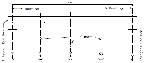
Typical Continuous Steel Structures – Integral End Bents:
751.14.1.3 Optimizing Girder Spacing on Non-Standard Roadways
Several items shall be considered when determining the girder spacing for non-standard roadways:
General Guidelines
In general, an economical girder arrangement is one that:
Balance M & V Distribution Factors. For efficiency, it is desired for all girders to be designed for the same loads, resulting in the same section for exterior and interior girders.
Practical Constraints
Some practical constraints to consider when optimizing girder spacing:
Number of girders. For consideration of future stage construction, there may be a minimum number of girders that should be considered.
Maximum Form Span. Precast panels and transparent forms have maximum span limits that should not be exceeded. For cases where conventional forms or corrugated steel forms are used, it is generally recognized that 12 ft girder spacing is a maximum practical limit to allow for future redecking.
Vertical Clearance and Deflection Requirements. It is expected that fewer girder lines would result in deeper girders. Vertical clearance or deflection constraints may dictate the use of more girder lines than optimum, or a shallower web than optimum.
Slab Overhang Limits. In order to use distribution factors provided in LRFD Table 4.6.2.2.2 for girder design, the roadway overhang shall not exceed AASHTO's specified limits, otherwise the structure shall be analyzed using a refined method of analysis specified in LRFD 4.6.3.
751.14.2 Design
751.14.2.1 Limit States and Load Factors
In general, each component shall satisfy the following equation:
Where:
| = Total factored force effect | |
| = Force effect | |
| = Load modifier | |
| = Load factor | |
| = Resistance factor | |
| = Nominal resistance | |
| = Factored resistance |
Limit States
The following limit states shall be considered for steel superstructure design:
- STRENGTH – I
- STRENGTH – III
- STRENGTH – IV(*)
- STRENGTH – V
- SERVICE – II
- FATIGUE
- For constant amplitude fatigue threshold (∆F)TH, see LRFD Table 6.6.1.2.3-1 for applicable detail. For base metal, except noncoated weathering steel, detail category “A” (∆F)TH = 24 ksi and for base metal, noncoated weathering steel, detail category “B” (∆F)TH = 16 ksi.
Combination for loads during construction and construction loads shall be evaluated at the Strength Limit State and Service Limit State in accordance with EPG 751.2.3.2 and LRFD 3.4.2.
(*) Use for bridges with high DL to LL ratios. Typically, bridges with spans > 200 ft.
See LRFD Table 3.4.1-1 and LRFD 3.4.2 for Loads and Load Factors applied at each given limit state.
Resistance factors
STRENGTH limit states, see LRFD Article 6.5.4.2
For all other limit states, = 1.00
751.14.2.2 Analysis Methods
MoDOT office practice generally utilizes the following:
The elastic stress at any location on the composite section due to the applied loads shall be the sum of the stresses caused by the loads applied separately at the following three stages:
Non-Composite Stage – The dead load of slab and haunching and beam self weight shall be analyzed at this stage. This stage shall also be used for any construction loading checks. The section properties used are of the steel section only.
Long Term Composite Stage – The dead load of barrier or railing, future wearing surface and any other appurtenances shall be analyzed at this stage. The section properties used are of the composite section of slab and beam assuming an elastic modulus of 3n for the slab. Where “n” is the modular ratio.
Short Term Composite Stage – Any live loading shall be analyzed at this stage. The section properties used are of the composite section of slab and beam assuming an elastic modulus of “n” for the slab. Where “n” is the modular ratio.
Composite regions shall be defined as regions where shear connectors are used to connect the steel section to a concrete deck. Simple spans and horizontally curved girders (see below) are designed as composite throughout.
Tension Flanges with Holes
Compact Design is not allowed in composite positive flexure regions where holes are located in the tension flange. Similarly, in negative flexure regions where holes are present in the tension flange the girders shall not be proportioned with compact or noncompact webs in accordance with LRFD Appendix A6. The placement of bolted field splices near DL contraflexure points will not preclude the use of compact design or LRFD Appendix A6 in adjacent regions. Girders with holes in the tension flange shall further meet the requirements of LRFD 6.10.1.8 Tension Flanges with Holes.
Wind
For girder and intermediate diaphragm and cross-frame design, wind acting on the top half of girder is distributed to deck and wind on the lower half is assumed to be carried by the bottom girder flange.
Analysis of Horizontally Curved Girders
Horizontally curved girders may be analyzed as straight girders if the following criteria are met:
- Girders are concentric
- Bent skews
- Similar girder stiffness throughout bridge width
- for all spans
Where:
| = girder radius | |
| = * (Arc span length) |
- Where:
= 1.0…simple spans: = 0.9…end continuous spans: = 0.8…interior continuous spans:
For straight girder analysis:
- Use the arc length as the span length
- Diaphragms and cross-frames treated as bracing members
- Shear connectors are omitted in negative moment regions
For horizontally curved girder analysis:
- Overturning (load-shifting) effects must be considered to contribute to the major-axis bending.
- Diaphragms and cross frames shall be designed as primary members.
- Design diaphragm connections to transfer forces to flanges.
- Shear connectors provided throughout girder length
- Lateral flange bending effects should be considered in the girder, shear connector, and flange splice design.
Note: Lateral flange bending stresses may be superimposed with stresses resulting from major-axis bending.
751.14.2.3 Intermediate Diaphragms and Cross Frames
Cross frames are located at all intermediate bents with continuous slabs.
Diaphragms or cross-frames for rolled beams shall be at least ½ the beam depth.
Girders shall be investigated for the effects of diaphragms or cross-frames for all stages of assumed construction procedures and the final condition.
Investigation shall include, but not be limited to:
- Transfer of lateral wind loads from the bottom of the girder to the deck and from the deck to the bearings.
- Stability of the bottom flange for all loads when it is in compression
- Stability of the top flange in compression prior to curing of the deck
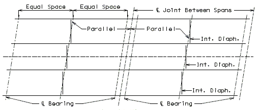
Straight Girder Layout
Typically the maximum intermediate diaphragm spacing shall be 25’-0”, unless determined otherwise for special designs.
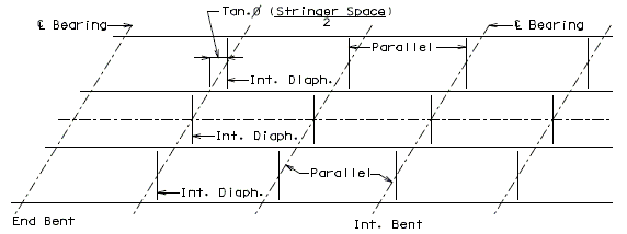
Curved Girder Layout (see Analysis of Horizontaly Curved Girders)
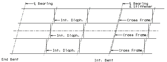
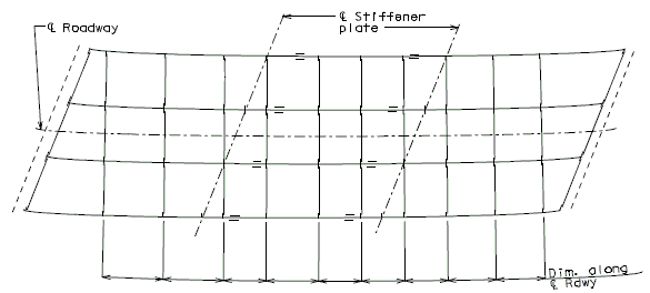
Maximum intermediate diaphragm spacing shall be 25’-0”, unless a lesser spacing is warranted by design. A lesser spacing may be warranted to satisfy LRFD Eq. 6.7.4.2-1 or to reduce lateral flange bending stresses.
Diaphragms shall be positioned radially and in line, except in bridges having extreme skews. Many different diaphragm spacing arrangements are possible. Attach diaphragm to a bearing stiffener where possible. The proposed diaphragm layout shall be reviewed with the Structural Project Manager prior to detailing on the plans.
A sketch of the desired diaphragm layout is given below.
751.14.2.4 End Diaphragms
General
Steel end diaphragms shall be located at all non-integral end bents and intermediate bents where continuity of the slab is broken (i.e. expansion joints). Integral end bent shall use a concrete diaphragm
Steel diaphragms for rolled beams shall be at least ½ the beam depth.
Steel diaphragms shall be investigated for all stages of assumed construction procedures and the final condition. Investigation shall include, but not be limited to:
- Transfer of lateral wind loads from the bottom of the girder to the deck and from the deck to the bearings.
- Stability of the bottom flange for all loads when it is in compression
- Stability of the top flange in compression prior to curing of the deck
- Distribution of vertical dead and live loads applied to the structure. (*)
(*) At the end of the bridge and intermediate points where the continuity of the slab is broken, the edges of the slab shall be supported by diaphragms or other suitable means as specified in LRFD 9.4.4. Top horizontal members shall be designed for vertical live and dead loads.
751.14.2.5 Part Elevation of Girders
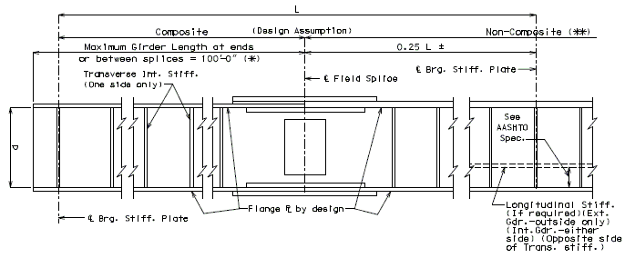
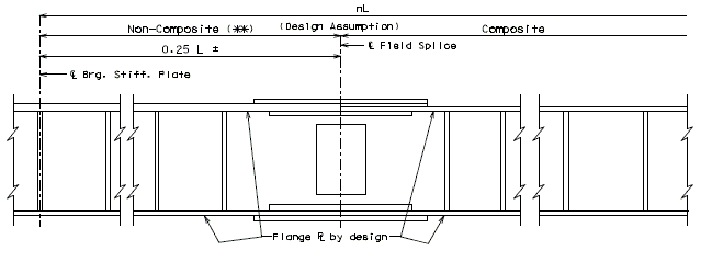
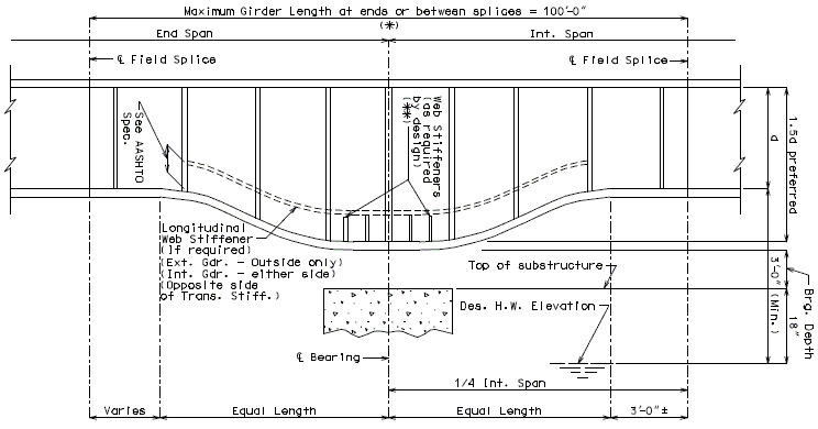
Use Variable depth section only as specified on Design Layout Sheet. Consult the Structural Project Manager for consideration of constant depth section in lieu of variable depth section based on design references or structural adequacy.
| (*) | See Structural Project Manager for approval to deviate from the Maximum Girder Length of plate girder sections. |
| (**) | See Design of Welded Structures by The James F. Lincoln Arc Welding Foundation, page 5.11-19. |
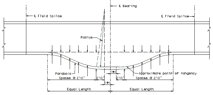
| (*) | Use 12" except for girders having bottom flange plate over 1 1/2" in thickness, then use 18". |
751.14.2.6 Other Requirements
Deflection
See EPG 751.2.4.2 for Live Load deflection criteria.
Compute at 1/4 points for bridges with spans 75 ft, Compute at 1/10 points for spans 75 ft.
Camber in Horizontally Curved Girders
Rolled Beams are required to be heat curved to develop a horizontal curvature. Plate girders may either be heat curved or the flanges cut to curvature.
Per LRFD 6.7.7.3 heat curving causes inherent residual stresses that result in camber losses during construction and for several months of in-service use. It is not required that these camber losses be accounted for in the camber profile. Industry leaders recognize that the calculation offered by LRFD 6.7.7.3 is theoretical and often inaccurate.
Minimum Negative Flexure Deck Reinforcement
See EPG 751.10.1.5
Bearing Stiffeners
- Bearing stiffener width shall be given in 1/2” increments and shall extend to within a 1/2” of the bottom flange.
- Bearing stiffener thickness shall be given in 1/8” increments.
- If the skewed stiffener option is used, make stiffeners on both sides of web for skews thru 45˚ the same size as the larger except in cases where overhang would be produced. This does not apply to end bearing stiffeners for skews over 45˚.
Diaphragms and Cross-Frames
Diaphragms and cross-frames and their connections shall:
- Meet all applicable limit states for the calculated force effects.
- Follow LRFD 4.6.2.7 for transfer of wind loads
- Meet slenderness requirements of LRFD 6.8.4 or 6.9.3
- Meet connection plate design requirements of LRFD 6.6.1.3.1
- Be designed for stability of top flange in compression during noncomposite stage, and bottom flange for all loads when in compression.
Top horizontal members in end diaphragms shall be designed for vertical live load and dead loads.
Cross-frames or diaphragms are either considered as bracing members or primary members as discussed in the section "Analysis of Horizontally Curved Girders"
Primary Members
When diaphragms are required to resist torsional forces, such as for horizontally curved girders or straight girders with highly skewed bents, they shall be designed as primary or main members. Primary members require that forces be computed and considered in the design of both the members and their connections to the girder.
Load Rating Check
The final girder sections and steel layout should be adequate for both the design and rating analysis. It is recommended to perform the load rating before finalizing the girder design.
751.14.3 Splice Design
751.14.3.1 Field Bolted Splice Design
General
In continuous spans, splices should be made at or near points of dead load contraflexure excluding future wearing surface. Web and Flange splices in areas of stress reversal shall be investigated for both positive and negative flexure.
In both web and flange splices, there shall not be less than two rows of bolts on each side of the joint. Oversize or slotted holes shall not be used in either the member or the splice plates at bolted splices.
Bolted splices for flexural members shall be designed using slip-critical connections as specified in LRFD 6.13.2.1.1. The connections shall also be proportioned to prevent slip during the erection of the steel and during the casting of the concrete deck.
The tensile stress on the flange should be checked per LRFD 6.10.1.8.
In bolted slip-critical connections subject to shear, the load is transferred between the connected parts by friction up to a certain level of force that is dependent upon the total clamping force on the faying surfaces and the coefficient of friction of the faying surfaces. As loading is increased to a level in excess of the frictional resistance between the faying surfaces, slip occurs, but failure in the sense does not occur. As a result, slip critical connections are able to resist even greater loads by shear and bearing against the connected material. The strength of the connection is not related to the slip load. Slip resistance, shear resistance and bending shall be computed separately. Any potential greater resistance due to combined effect is ignored.
Bolt Design
Slip Resistance
| See SEG 20-02 for Galvanized Bolted Connection Design Requirements. |
Splices shall be designed as slip critical connections with Class B surface preparation and standard holes. Slip shall be checked against the maximum of the Service-II limit stresses and the Strength-I construction stresses due to slab pouring sequences. All splice bolts shall be 7/8” diameter ASTM F3125 Grade A325 bolts with a minimum pretension of 39 kips upon girder erection.
Shear Resistance
The Bolt Shear Resistance shall be adequate to resist loads at the Strength-I limit state. (See Loads in this article.)
If a filler plate not less than 0.25” in thickness is used in a flange splice then the Bolt Shear Resistance shall be reduced by the following factor:
Where:
| = | |
| = sum of the area of the fillers on the top and bottom of the connected plate | |
| = smaller of either the connected plate area or the sum of the splice plate areas on the top and bottom of the connected plate |
If the distance between extreme fasteners on one side of a flange splice (joint length) is greater than 50 inches then the Bolt Shear Resistance shall be reduced by 20%. Excluding the threads from the shear plane (when applicable) in order to reduce the overall length of a joint is preferred over reducing the Bolt Shear Resistance for large joint lengths.
Threads may be excluded from the shear plane when the minimum splice plate thickness at the joint is greater than 5/8”. Otherwise, the bolt threads shall be assumed to be included in the shear plane.
Thread Embedment, = - - washer height – (stick-out)
= 1.5" - 55/64" - 0" - 0" = 0.641" or 3/4" rounded up to the nearest 1/8”.
Flange Bolt Patterns
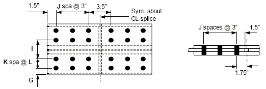
The minimum distance from the center of any fastener in a standard hole to a sheared or thermally cut edge shall be 1 1/2 inches for 7/8” diameter fasteners. The minimum distance between centers of fasteners in standard holes shall be three times the diameter of the fastener, but shall not be less than 3 inches parallel to the line of force for 7/8” diameter fasteners. The minimum edge distance shall be 2 inches for top flange outer splice plates to allow for panel clearance.
Uniform bolt patterns are preferred in all cases except that a staggered pattern may be used for flanges that are 14 and 15 inches wide. A staggered bolt pattern reduces the distance between rows of bolts so panels can be placed along the edges of the plate.
Bolt tightening clearances may become a problem for thick inner flange splice plates or flange bolt patterns that use a narrow bolt gauge, I, across the web. A thorough review is required to ensure that a 2.5” diameter socket with 1/16” clearance can be used. Typically, when bolt tightening clearances are an issue the bolt gauge, I, needs to be increased but the sealing check shall not be violated. If increasing the bolt gauge is not an option the clearance to web bolts, e, shall be increased the minimum extent necessary to maintain a practical uniform web bolt pattern.

Flange Splice Plate Design
Flange Width Transitions
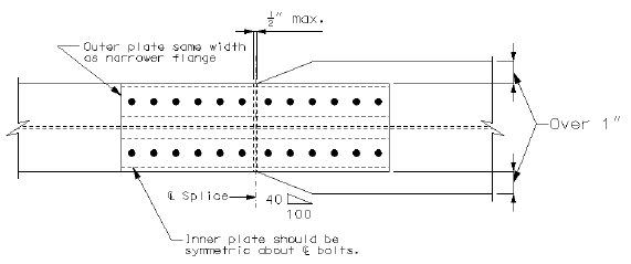
When the width of the flanges being spliced differs by more than 2”, the larger flange shall be beveled as shown below.
Flange Splice Dimensions
- Minimum thickness of splice plate = 3/8”
- Splice plate thickness increment = 1/8”
- At the strength limit state, if the gross areas of the outer and inner splice plates vary by less than 10% then the shear force can be distributed by double shear. Otherwise, the shear force must be distributed to each shear plane by the percentage of the gross area of the plate in contact with the shear plane from the total gross area of splice plates. (Note: Double shear can be assumed at the service limit state for all cases)
- The total gross area of the splice plates shall be greater than the gross area of the smaller flange.
- Bolt holes are considered to be 1” in diameter for the purpose of determining the net flange or splice area.
- Inner splice plates shall be symmetric for uniform bolt patterns.
Loads
- Strength I - Splice plates shall be designed to resist a minimum design stress equal to the average of the factored elastic flexural stress at the mid-depth of the flange and the yield strength of the flange , but shall not be less than .
- Service II – Use factored loading to determine design force.
- Construction – Use factored loading to determine design force.
- Fatigue – Use factored loading to determine design stress range.
Resistance
The nominal flexural resistance of the flange at the point of splice at the strength limit state shall be assumed to be equal to the specified minimum yield strength of the flange . For hybrid sections, a hybrid factor shall be used to increase the stress seen by the flange when the factored elastic flexural stress exceeds at the top or bottom of the web.
Flange splice plates shall be checked for:
- Tensile Resistance @ Strength-I Limit State
- Yielding of Gross Section
- Fracture of Net Section
- Block Shear Rupture of Net Section
- Compressive Resistance @ Strength-I Limit State
- Fatigue Resistance @ Fatigue and Fracture Limit State
- Permanent Deflection under Construction loads
Note: The last two checks may be ignored if the sum of the gross splice plate areas is greater than the gross area of the flange.
Girder flange shall be checked for:
- Tensile Resistance @ Strength-I Limit State
- Fracture of Net Section
- Block Shear Rupture of Net Section
- Bearing Resistance @ Strength-I Limit State
Web Splice Plate Design
Web Splice Dimensions
- Webs shall be spliced symmetrically by plates on each side.
- These plates shall extend as near as practical for the full depth between flanges.
- The thickness of the web splice plates shall be 3/8”. The total gross area of the splice plates shall be greater than the gross area of the smaller web at splice.
- Bolt holes are considered to be 1” in diameter for the purpose of determining the net web or splice area.
Loads
Web splice plates and their connections shall be designed for shear, the moment due to the eccentricity of the shear at the point of splice, and the portion of the flexural moment assumed to be resisted by the web at the point of splice.
- Strength I - If Vu>0.5Vr, then the design shear (Vuw) shall be equal to the average of the factored shear loading (Vu) and the factored shear resistance (Vr) of the smaller web. Otherwise, Vuw=1.5Vu. The design moment shall be calculated using the design stresses determined for flange design.
- Service II – Use the factored loading to determine the design shear and moment.
- Construction – Use the factored loading to determine the design moment and shear.
- Fatigue – Use the factored loading to determine the design stress range.
Resistance
The factored shear resistance of the web shall be determined as specified in LRFD 6.12.1.2.3. For hybrid sections the web shall resist only the stress not exceeding the yield strength of the web ). A hybrid factor shall be used to reduce the stress seen by the web when the factored elastic flexural stress exceeds at the top or bottom of the web.
Web splice plates shall be checked for:
- Shear Resistance @ Strength-I Limit State
- Yielding of Gross Section
- Fracture of Net Section
- Block Shear Rupture of Net Section
- Flexural Resistance @ Strength-I Limit State
- Fatigue Resistance @ Fatigue and Fracture Limit State
- Permanent Deflection under construction loads
Note: The last two checks may be ignored if the sum of the gross splice plate areas is greater than the gross area of the web.
Girder web shall be checked for:
- Bearing Resistance @ Strength-I Limit State
Design Tools
Field Flange Splice Tables
The flange tables were developed assuming a symmetric girder section with the tension flange near yield. The flange splice plates were designed to carry this tension force along with the associated compression force found on the opposing flange. Net fracture of the flange is eliminated by limiting the factored tensile stress, , to the maximums allowed in the table below. When the flange section or steel grade changes at a splice, use the narrower flange. For flanges with the same width, the smaller flange strength may be used from the table as shown below. Note: The tables are not designed for the lateral bending effects induced in horizontally curved bridges. Lateral forces may increase the design bolt force above the value used in the tables.
Which flange should be used to enter in the tables?
| A. | Grade 50W – 18” x 2” | vs. | B. | Grade 70W – 18” x 1.375” |
| 50ksi x 18” x 2” = 1800 k | > | 70ksi x 18” x 1.375” = 1733 k | ||
Use Flange B from the table (50W splice plate)
Field Web Splice Tables
The dimensions of the web splices shown in the tables are based on the assumption that the factored shear force is equal to the web’s unstiffened shear capacity . Also, the moment required to be resisted by the web is assumed to be half of the elastic web moment capacity . If the design shear is greater than the unstiffened shear capacity, , (i.e, stiffened webs) then the web splice shall be designed in accordance with LRFD 6.13.6.1.4b. Flange splices shall be checked to ensure that they can resist the entire moment applied to the girder section at the centerline of the splice, or the web and flange splices will have to be designed in accordance with LRFD 6.13.6.1.4b & c. Lateral bending effects from horizontal curvature need not be considered in the design of the web splice.
| Flange Width | Flange Grade | ||
| 50 | 50W | 70W | |
| 12” | 45.5 | 49.0 | 63.0 |
| 13” | 46.2 | 49.7 | 64.0 |
| 14” | 46.0 | 49.6 | 63.7 |
| 15” | 46.6 | 50 | 64.5 |
| 16” | 40.9 | 44.1 | 56.7 |
| 17” | 41.7 | 45.0 | 57.8 |
| 18” | 42.5 | 45.7 | 58.8 |
| 19” | 43.1 | 46.4 | 59.7 |
| 20” | 43.7 | 47.0 | 60.5 |
| 21” | 44.2 | 47.6 | 61.2 |
| 22” | 39.7 | 42.8 | 55.0 |
| 23” | 40.4 | 43.5 | 55.9 |
| 24” | 40.9 | 44.1 | 56.7 |
Maximum stresses are dependant on bolt pattern.
751.14.3.2 Plate Girder - Flange Splice Tables
Flange Plate Size: 12" thru 24" (2, 4 or 6 rows of Bolts) ASTM A709, Grade 50 and 50W Flanges, Grade 50 and 50W Splice

| Flange | Filler Plate Thick. |
Outer Plate | Inner Plates | Uniform Bolt Pattern | WT./FLG. with 7/8" Bolts (lb) | |||||||||
| A (in) |
B (in) |
C (in) |
D (in) |
E (in) |
F (in) |
G (in) |
I (in) |
J (in) |
K (in) |
L (in) |
Total # of Bolts | |||
| 12 x 3/4" | < 1/4" | 12 | 0.500 | 36.5 | 4 | 0.625 | 36.5 | 3 | 6 | 5 | 0 | 0 | 24 | 136.7 |
| other | 12 | 0.500 | 54.5 | 4 | 0.625 | 54.5 | 3 | 6 | 8 | 0 | 0 | 36 | 204.2 | |
| 12 x 7/8" | < 1/4" | 12 | 0.625 | 42.5 | 4.5 | 0.625 | 42.5 | 2.75 | 6.5 | 6 | 0 | 0 | 28 | 184.8 |
| other | 12 | 0.625 | 60.5 | 4.5 | 0.750 | 60.5 | 2.75 | 6.5 | 9 | 0 | 0 | 40 | 282.5 | |
| 12 x 1" | < 1/4" | 12 | 0.625 | 42.5 | 4.5 | 0.750 | 42.5 | 2.75 | 6.5 | 6 | 0 | 0 | 28 | 198.3 |
| other | 12 | 0.625 | 66.5 | 4.5 | 0.750 | 66.5 | 2.75 | 6.5 | 10 | 0 | 0 | 44 | 310.5 | |
| 12 x 1 1/8" * | < 1/4" | 12 | 0.750 | 42.5 | 5 | 0.750 | 42.5 | 2.5 | 7 | 6 | 0 | 0 | 28 | 225.4 |
| other | 12 | 0.750 | 60.5 | 5 | 0.750 | 60.5 | 2.5 | 7 | 9 | 0 | 0 | 40 | 321.1 | |
| 12 x 1 1/4" * | < 1/4" | 12 | 0.750 | 48.5 | 5 | 0.750 | 48.5 | 2.5 | 7 | 7 | 0 | 0 | 32 | 257.3 |
| other | 12 | 0.750 | 66.5 | 5 | 0.750 | 66.5 | 2.5 | 7 | 10 | 0 | 0 | 44 | 352.9 | |
| 12 x 1 3/8" * | < 1/4" | 12 | 0.875 | 54.5 | 5 | 0.875 | 54.5 | 2.5 | 7 | 8 | 0 | 0 | 36 | 331.7 |
| other | 12 | 0.875 | 66.5 | 5 | 1.000 | 66.5 | 2.5 | 7 | 10 | 0 | 0 | 44 | 428.4 | |
| 12 x 1 1/2" * | < 1/4" | 12 | 0.875 | 54.5 | 5 | 1.000 | 54.5 | 2.5 | 7 | 8 | 0 | 0 | 36 | 351.0 |
| other | 12 | 0.875 | 66.5 | 5 | 1.000 | 66.5 | 2.5 | 7 | 10 | 0 | 0 | 44 | 428.4 | |
| 12 x 1 5/8" * | < 1/4" | 12 | 1.000 | 54.5 | 5 | 1.125 | 54.5 | 2.5 | 7 | 8 | 0 | 0 | 36 | 393.5 |
| other | 12 | 1.000 | 66.5 | 5 | 1.125 | 66.5 | 2.5 | 7 | 10 | 0 | 0 | 44 | 480.2 | |
| 12 x 1 3/4" * | < 1/4" | 12 | 1.000 | 60.5 | 5 | 1.125 | 60.5 | 2.5 | 7 | 9 | 0 | 0 | 40 | 436.9 |
| other | 12 | 1.000 | 72.5 | 5 | 1.125 | 72.5 | 2.5 | 7 | 11 | 0 | 0 | 48 | 523.6 | |
| 12 x 1 7/8" * | < 1/4" | 12 | 1.125 | 66.5 | 5 | 1.250 | 66.5 | 2.5 | 7 | 10 | 0 | 0 | 44 | 532.1 |
| other | 12 | 1.125 | 72.5 | 5 | 1.250 | 72.5 | 2.5 | 7 | 11 | 0 | 0 | 48 | 580.1 | |
| 12 x 2" * | < 1/4" | 12 | 1.250 | 66.5 | 5 | 1.375 | 66.5 | 2.5 | 7 | 10 | 0 | 0 | 44 | 583.9 |
| other | 12 | 1.250 | 78.5 | 5 | 1.375 | 78.5 | 2.5 | 7 | 12 | 0 | 0 | 52 | 689.4 | |
| 12 x 2 1/8" * | < 1/4" | 12 | 1.250 | 72.5 | 5 | 1.375 | 72.5 | 2.5 | 7 | 11 | 0 | 0 | 48 | 636.7 |
| other | 12 | 1.250 | 84.5 | 5 | 1.375 | 84.5 | 2.5 | 7 | 13 | 0 | 0 | 56 | 742.1 | |
| 12 x 2 1/4" * | < 1/4" | 12 | 1.375 | 78.5 | 5 | 1.500 | 78.5 | 2.5 | 7 | 12 | 0 | 0 | 52 | 750.6 |
| other | 12 | 1.375 | 90.5 | 5 | 1.500 | 90.5 | 2.5 | 7 | 14 | 0 | 0 | 60 | 865.4 | |
| * Bolt threads are EXCLUDED from shear plane | ||||||||||||||
| Flange | Filler Plate Thick. |
Outer Plate | Inner Plates | Uniform Bolt Pattern | WT./FLG. with 7/8" Bolts (lb) | |||||||||
| A (in) |
B (in) |
C (in) |
D (in) |
E (in) |
F (in) |
G (in) |
I (in) |
J (in) |
K (in) |
L (in) |
Total # of Bolts | |||
| 13 x 3/4" | < 1/4" | 13 | 0.500 | 36.5 | 4 | 0.750 | 36.5 | 3.5 | 6 | 5 | 0 | 0 | 24 | 152.2 |
| other | 13 | 0.500 | 54.5 | 4 | 0.750 | 54.5 | 3.5 | 6 | 8 | 0 | 0 | 36 | 227.4 | |
| 13 x 7/8" | < 1/4" | 13 | 0.625 | 42.5 | 4.5 | 0.750 | 42.5 | 3.25 | 6.5 | 6 | 0 | 0 | 28 | 205.9 |
| other | 13 | 0.625 | 66.5 | 4.5 | 0.875 | 66.5 | 3.25 | 6.5 | 10 | 0 | 0 | 44 | 343.5 | |
| 13 x 1" | < 1/4" | 13 | 0.625 | 48.5 | 4.5 | 0.875 | 48.5 | 3.25 | 6.5 | 7 | 0 | 0 | 32 | 250.4 |
| other | 13 | 0.625 | 72.5 | 4.5 | 0.875 | 72.5 | 3.25 | 6.5 | 11 | 0 | 0 | 48 | 374.5 | |
| 13 x 1 1/8" * | < 1/4" | 13 | 0.750 | 48.5 | 5 | 0.875 | 48.5 | 3 | 7 | 7 | 0 | 0 | 32 | 284.8 |
| other | 13 | 0.750 | 66.5 | 5 | 0.875 | 66.5 | 3 | 7 | 10 | 0 | 0 | 44 | 390.7 | |
| 13 x 1 1/4" * | < 1/4" | 13 | 0.750 | 48.5 | 5 | 0.875 | 48.5 | 3 | 7 | 7 | 0 | 0 | 32 | 284.8 |
| other | 13 | 0.750 | 66.5 | 5 | 0.875 | 66.5 | 3 | 7 | 10 | 0 | 0 | 44 | 390.7 | |
| 13 x 1 3/8" * | < 1/4" | 13 | 0.750 | 54.5 | 5 | 1.000 | 54.5 | 3 | 7 | 8 | 0 | 0 | 36 | 339.4 |
| other | 13 | 0.750 | 66.5 | 5 | 1.000 | 66.5 | 3 | 7 | 10 | 0 | 0 | 44 | 414.2 | |
| 13 x 1 1/2" * | < 1/4" | 13 | 0.875 | 54.5 | 5 | 1.125 | 54.5 | 3 | 7 | 8 | 0 | 0 | 36 | 383.9 |
| other | 13 | 0.875 | 72.5 | 5 | 1.125 | 72.5 | 3 | 7 | 11 | 0 | 0 | 48 | 510.7 | |
| 13 x 1 5/8" * | < 1/4" | 13 | 1.000 | 60.5 | 5 | 1.250 | 60.5 | 3 | 7 | 9 | 0 | 0 | 40 | 475.5 |
| other | 13 | 1.000 | 72.5 | 5 | 1.250 | 72.5 | 3 | 7 | 11 | 0 | 0 | 48 | 569.8 | |
| 13 x 1 3/4" * | < 1/4" | 13 | 1.000 | 66.5 | 5 | 1.250 | 66.5 | 3 | 7 | 10 | 0 | 0 | 44 | 522.7 |
| other | 13 | 1.000 | 78.5 | 5 | 1.250 | 78.5 | 3 | 7 | 12 | 0 | 0 | 52 | 617.0 | |
| 13 x 1 7/8" * | < 1/4" | 13 | 1.125 | 72.5 | 5 | 1.250 | 72.5 | 3 | 7 | 11 | 0 | 0 | 48 | 603.2 |
| other | 13 | 1.125 | 84.5 | 5 | 1.250 | 84.5 | 3 | 7 | 13 | 0 | 0 | 56 | 703.1 | |
| 13 x 2" * | < 1/4" | 13 | 1.250 | 78.5 | 5 | 1.375 | 78.5 | 3 | 7 | 12 | 0 | 0 | 52 | 717.2 |
| other | 13 | 1.250 | 90.5 | 5 | 1.500 | 90.5 | 3 | 7 | 14 | 0 | 0 | 60 | 859.0 | |
| 13 x 2 1/8" * | < 1/4" | 13 | 1.250 | 78.5 | 5 | 1.500 | 78.5 | 3 | 7 | 12 | 0 | 0 | 52 | 745.0 |
| other | 13 | 1.250 | 90.5 | 5 | 1.500 | 90.5 | 3 | 7 | 14 | 0 | 0 | 60 | 859.0 | |
| 13 x 2 1/4" * | < 1/4" | 13 | 1.375 | 84.5 | 5 | 1.625 | 84.5 | 3 | 7 | 13 | 0 | 0 | 56 | 870.9 |
| other | 13 | 1.375 | 96.5 | 5 | 1.625 | 96.5 | 3 | 7 | 15 | 0 | 0 | 64 | 994.6 | |
| * Bolt threads are EXCLUDED from shear plane | ||||||||||||||
| Flange | Filler Plate Thick. |
Outer Plate | Inner Plates | Staggered Bolt Pattern | WT./FLG. with 7/8" Bolts (lb) | |||||||||
| A (in) |
B (in) |
C (in) |
D (in) |
E (in) |
F (in) |
G (in) |
I (in) |
J (in) |
K (in) |
L (in) |
Total # of Bolts | |||
| 14 x 3/4" | < 1/4" | 14 | 0.500 | 21.5 | 5.5 | 0.625 | 21.5 | 2 | 5 | 2 | 1 | 2.5 | 24 | 107.4 |
| other | 14 | 0.500 | 33.5 | 5.5 | 0.625 | 33.5 | 2 | 5 | 4 | 1 | 2.5 | 40 | 169.8 | |
| 14 x 7/8" | < 1/4" | 14 | 0.500 | 27.5 | 5.5 | 0.750 | 27.5 | 2 | 5 | 3 | 1 | 2.5 | 32 | 149.3 |
| other | 14 | 0.500 | 39.5 | 5.5 | 0.750 | 39.5 | 2 | 5 | 5 | 1 | 2.5 | 48 | 216.4 | |
| 14 x 1" | < 1/4" | 14 | 0.625 | 27.5 | 5.5 | 0.750 | 27.5 | 2 | 5 | 3 | 1 | 2.5 | 32 | 163.0 |
| other | 14 | 0.625 | 45.5 | 5.5 | 0.750 | 45.5 | 2 | 5 | 6 | 1 | 2.5 | 56 | 272.5 | |
| 14 x 1 1/8" * | < 1/4" | 14 | 0.750 | 27.5 | 5.5 | 0.750 | 27.5 | 2 | 5 | 3 | 1 | 2.5 | 32 | 176.6 |
| other | 14 | 0.750 | 39.5 | 5.5 | 0.750 | 39.5 | 2 | 5 | 5 | 1 | 2.5 | 48 | 255.6 | |
| 14 x 1 1/4" * | < 1/4" | 14 | 0.875 | 33.5 | 5.5 | 0.875 | 33.5 | 2 | 5 | 4 | 1 | 2.5 | 40 | 245.8 |
| other | 14 | 0.875 | 39.5 | 5.5 | 1.000 | 39.5 | 2 | 5 | 5 | 1 | 2.5 | 48 | 306.0 | |
| 14 x 1 3/8" * | < 1/4" | 14 | 0.875 | 33.5 | 5.5 | 1.000 | 33.5 | 2 | 5 | 4 | 1 | 2.5 | 40 | 258.9 |
| other | 14 | 0.875 | 45.5 | 5.5 | 1.000 | 45.5 | 2 | 5 | 6 | 1 | 2.5 | 56 | 353.2 | |
| 14 x 1 1/2" * | < 1/4" | 14 | 0.875 | 33.5 | 5.5 | 1.125 | 33.5 | 2 | 5 | 4 | 1 | 2.5 | 40 | 271.9 |
| other | 14 | 0.875 | 45.5 | 5.5 | 1.125 | 45.5 | 2 | 5 | 6 | 1 | 2.5 | 56 | 370.9 | |
| 14 x 1 5/8" * | < 1/4" | 14 | 1.000 | 39.5 | 5.5 | 1.125 | 39.5 | 2 | 5 | 5 | 1 | 2.5 | 48 | 341.0 |
| other | 14 | 1.000 | 45.5 | 5.5 | 1.125 | 45.5 | 2 | 5 | 6 | 1 | 2.5 | 56 | 393.5 | |
| 14 x 1 3/4" * | < 1/4" | 14 | 1.125 | 39.5 | 5.5 | 1.250 | 39.5 | 2 | 5 | 5 | 1 | 2.5 | 48 | 376.0 |
| other | 14 | 1.125 | 45.5 | 5.5 | 1.250 | 45.5 | 2 | 5 | 6 | 1 | 2.5 | 56 | 433.8 | |
| 14 x 1 7/8" * | < 1/4" | 14 | 1.250 | 45.5 | 5.5 | 1.250 | 45.5 | 2 | 5 | 6 | 1 | 2.5 | 56 | 456.4 |
| other | 14 | 1.250 | 51.5 | 5.5 | 1.250 | 51.5 | 2 | 5 | 7 | 1 | 2.5 | 64 | 517.2 | |
| 14 x 2" * | < 1/4" | 14 | 1.250 | 45.5 | 5.5 | 1.375 | 45.5 | 2 | 5 | 6 | 1 | 2.5 | 56 | 474.1 |
| other | 14 | 1.250 | 51.5 | 5.5 | 1.375 | 51.5 | 2 | 5 | 7 | 1 | 2.5 | 64 | 537.2 | |
| 14 x 2 1/8" * | < 1/4" | 14 | 1.375 | 51.5 | 5.5 | 1.375 | 51.5 | 2 | 5 | 7 | 1 | 2.5 | 64 | 562.8 |
| other | 14 | 1.375 | 57.5 | 5.5 | 1.375 | 57.5 | 2 | 5 | 8 | 1 | 2.5 | 72 | 628.9 | |
| 14 x 2 1/4" * | < 1/4" | 14 | 1.500 | 51.5 | 5.5 | 1.500 | 51.5 | 2 | 5 | 7 | 1 | 2.5 | 64 | 608.4 |
| other | 14 | 1.500 | 63.5 | 5.5 | 1.500 | 63.5 | 2 | 5 | 9 | 1 | 2.5 | 80 | 751.2 | |
| * Bolt threads are EXCLUDED from shear plane | ||||||||||||||
| Flange | Filler Plate Thick. |
Outer Plate | Inner Plates | Staggered Bolt Pattern | WT./FLG. with 7/8" Bolts (lb) | |||||||||
| A (in) |
B (in) |
C (in) |
D (in) |
E (in) |
F (in) |
G (in) |
I (in) |
J (in) |
K (in) |
L (in) |
Total # of Bolts | |||
| 15 x 3/4" | < 1/4" | 15 | 0.500 | 27.5 | 6.5 | 0.500 | 27.5 | 2 | 6 | 3 | 1 | 2.5 | 32 | 139.6 |
| other | 15 | 0.500 | 39.5 | 6.5 | 0.500 | 39.5 | 2 | 6 | 5 | 1 | 2.5 | 48 | 202.4 | |
| 15 x 7/8" | < 1/4" | 15 | 0.500 | 27.5 | 6.5 | 0.625 | 27.5 | 2 | 6 | 3 | 1 | 2.5 | 32 | 152.2 |
| other | 15 | 0.500 | 39.5 | 6.5 | 0.625 | 39.5 | 2 | 6 | 5 | 1 | 2.5 | 48 | 220.6 | |
| 15 x 1" | < 1/4" | 15 | 0.625 | 33.5 | 6.5 | 0.625 | 33.5 | 2 | 6 | 4 | 1 | 2.5 | 40 | 204.2 |
| other | 15 | 0.625 | 45.5 | 6.5 | 0.625 | 45.5 | 2 | 6 | 6 | 1 | 2.5 | 56 | 279.0 | |
| 15 x 1 1/8" | < 1/4" | 15 | 0.625 | 33.5 | 6.5 | 0.750 | 33.5 | 2 | 6 | 4 | 1 | 2.5 | 40 | 219.7 |
| other | 15 | 0.625 | 51.5 | 6.5 | 0.750 | 51.5 | 2 | 6 | 7 | 1 | 2.5 | 64 | 340.1 | |
| 15 x 1 1/4" * | < 1/4" | 15 | 0.750 | 33.5 | 6.5 | 0.875 | 33.5 | 2 | 6 | 4 | 1 | 2.5 | 40 | 252.9 |
| other | 15 | 0.750 | 45.5 | 6.5 | 0.875 | 45.5 | 2 | 6 | 6 | 1 | 2.5 | 56 | 345.1 | |
| 15 x 1 3/8" * | < 1/4" | 15 | 0.875 | 33.5 | 6.5 | 0.875 | 33.5 | 2 | 6 | 4 | 1 | 2.5 | 40 | 270.7 |
| other | 15 | 0.875 | 45.5 | 6.5 | 0.875 | 45.5 | 2 | 6 | 6 | 1 | 2.5 | 56 | 369.3 | |
| 15 x 1 1/2" * | < 1/4" | 15 | 0.875 | 39.5 | 6.5 | 1.000 | 39.5 | 2 | 6 | 5 | 1 | 2.5 | 48 | 338.2 |
| other | 15 | 0.875 | 45.5 | 6.5 | 1.000 | 45.5 | 2 | 6 | 6 | 1 | 2.5 | 56 | 390.3 | |
| 15 x 1 5/8" * | < 1/4" | 15 | 1.000 | 39.5 | 6.5 | 1.000 | 39.5 | 2 | 6 | 5 | 1 | 2.5 | 48 | 359.2 |
| other | 15 | 1.000 | 51.5 | 6.5 | 1.000 | 51.5 | 2 | 6 | 7 | 1 | 2.5 | 64 | 469.7 | |
| 15 x 1 3/4" * | < 1/4" | 15 | 1.125 | 45.5 | 6.5 | 1.125 | 45.5 | 2 | 6 | 6 | 1 | 2.5 | 56 | 459.6 |
| other | 15 | 1.125 | 51.5 | 6.5 | 1.125 | 51.5 | 2 | 6 | 7 | 1 | 2.5 | 64 | 520.8 | |
| 15 x 1 7/8" * | < 1/4" | 15 | 1.125 | 45.5 | 6.5 | 1.250 | 45.5 | 2 | 6 | 6 | 1 | 2.5 | 56 | 480.6 |
| other | 15 | 1.125 | 51.5 | 6.5 | 1.250 | 51.5 | 2 | 6 | 7 | 1 | 2.5 | 64 | 544.5 | |
| 15 x 2" * | < 1/4" | 15 | 1.250 | 51.5 | 6.5 | 1.250 | 51.5 | 2 | 6 | 7 | 1 | 2.5 | 64 | 571.9 |
| other | 15 | 1.250 | 57.5 | 6.5 | 1.250 | 57.5 | 2 | 6 | 8 | 1 | 2.5 | 72 | 639.1 | |
| 15 x 2 1/8" * | < 1/4" | 15 | 1.250 | 51.5 | 6.5 | 1.375 | 51.5 | 2 | 6 | 7 | 1 | 2.5 | 64 | 595.7 |
| other | 15 | 1.250 | 57.5 | 6.5 | 1.375 | 57.5 | 2 | 6 | 8 | 1 | 2.5 | 72 | 665.6 | |
| 15 x 2 1/4" * | < 1/4" | 15 | 1.375 | 51.5 | 6.5 | 1.375 | 51.5 | 2 | 6 | 7 | 1 | 2.5 | 64 | 623.0 |
| other | 15 | 1.375 | 63.5 | 6.5 | 1.375 | 63.5 | 2 | 6 | 9 | 1 | 2.5 | 80 | 769.2 | |
| * Bolt threads are EXCLUDED from shear plane | ||||||||||||||
| Flange | Filler Plate Thick. |
Outer Plate | Inner Plates | Uniform Bolt Pattern | WT./FLG. with 7/8" Bolts (lb) | |||||||||
| A (in) |
B (in) |
C (in) |
D (in) |
E (in) |
F (in) |
G (in) |
I (in) |
J (in) |
K (in) |
L (in) |
Total # of Bolts | |||
| 16 x 3/4" | < 1/4" | 16 | 0.500 | 24.5 | 7 | 0.500 | 24.5 | 2 | 6 | 3 | 1 | 3 | 32 | 134.6 |
| other | 16 | 0.500 | 36.5 | 7 | 0.500 | 36.5 | 2 | 6 | 5 | 1 | 3 | 48 | 200.9 | |
| 16 x 7/8" | < 1/4" | 16 | 0.500 | 24.5 | 7 | 0.500 | 24.5 | 2 | 6 | 3 | 1 | 3 | 32 | 134.6 |
| other | 16 | 0.500 | 42.5 | 7 | 0.500 | 42.5 | 2 | 6 | 6 | 1 | 3 | 56 | 234.0 | |
| 16 x 1" | < 1/4" | 16 | 0.625 | 30.5 | 7 | 0.625 | 30.5 | 2 | 6 | 4 | 1 | 3 | 40 | 200.2 |
| other | 16 | 0.625 | 42.5 | 7 | 0.750 | 42.5 | 2 | 6 | 6 | 1 | 3 | 56 | 300.3 | |
| 16 x 1 1/8" | < 1/4" | 16 | 0.625 | 30.5 | 7 | 0.750 | 30.5 | 2 | 6 | 4 | 1 | 3 | 40 | 215.3 |
| other | 16 | 0.625 | 48.5 | 7 | 0.750 | 48.5 | 2 | 6 | 7 | 1 | 3 | 64 | 342.7 | |
| 16 x 1 1/4" * | < 1/4" | 16 | 0.750 | 30.5 | 7 | 0.750 | 30.5 | 2 | 6 | 4 | 1 | 3 | 40 | 232.6 |
| other | 16 | 0.750 | 42.5 | 7 | 0.750 | 42.5 | 2 | 6 | 6 | 1 | 3 | 56 | 324.4 | |
| 16 x 1 3/8" * | < 1/4" | 16 | 0.750 | 30.5 | 7 | 0.875 | 30.5 | 2 | 6 | 4 | 1 | 3 | 40 | 247.7 |
| other | 16 | 0.750 | 42.5 | 7 | 0.875 | 42.5 | 2 | 6 | 6 | 1 | 3 | 56 | 345.4 | |
| 16 x 1 1/2" * | < 1/4" | 16 | 0.875 | 36.5 | 7 | 0.875 | 36.5 | 2 | 6 | 5 | 1 | 3 | 48 | 317.3 |
| other | 16 | 0.875 | 48.5 | 7 | 0.875 | 48.5 | 2 | 6 | 7 | 1 | 3 | 64 | 421.8 | |
| 16 x 1 5/8" * | < 1/4" | 16 | 0.875 | 36.5 | 7 | 1.000 | 36.5 | 2 | 6 | 5 | 1 | 3 | 48 | 335.4 |
| other | 16 | 0.875 | 48.5 | 7 | 1.000 | 48.5 | 2 | 6 | 7 | 1 | 3 | 64 | 445.9 | |
| 16 x 1 3/4" * | < 1/4" | 16 | 1.000 | 36.5 | 7 | 1.125 | 36.5 | 2 | 6 | 5 | 1 | 3 | 48 | 374.2 |
| other | 16 | 1.000 | 48.5 | 7 | 1.125 | 48.5 | 2 | 6 | 7 | 1 | 3 | 64 | 497.5 | |
| 16 x 1 7/8" * | < 1/4" | 16 | 1.125 | 42.5 | 7 | 1.125 | 42.5 | 2 | 6 | 6 | 1 | 3 | 56 | 459.9 |
| other | 16 | 1.125 | 54.5 | 7 | 1.125 | 54.5 | 2 | 6 | 8 | 1 | 3 | 72 | 590.0 | |
| 16 x 2" * | < 1/4" | 16 | 1.125 | 42.5 | 7 | 1.250 | 42.5 | 2 | 6 | 6 | 1 | 3 | 56 | 481.0 |
| other | 16 | 1.125 | 54.5 | 7 | 1.250 | 54.5 | 2 | 6 | 8 | 1 | 3 | 72 | 617.0 | |
| 16 x 2 1/8" * | < 1/4" | 16 | 1.250 | 48.5 | 7 | 1.250 | 48.5 | 2 | 6 | 7 | 1 | 3 | 64 | 576.5 |
| other | 16 | 1.250 | 60.5 | 7 | 1.250 | 60.5 | 2 | 6 | 9 | 1 | 3 | 80 | 719.3 | |
| 16 x 2 1/4" * | < 1/4" | 16 | 1.250 | 48.5 | 7 | 1.375 | 48.5 | 2 | 6 | 7 | 1 | 3 | 64 | 600.6 |
| other | 16 | 1.250 | 60.5 | 7 | 1.375 | 60.5 | 2 | 6 | 9 | 1 | 3 | 80 | 749.4 | |
| * Bolt threads are EXCLUDED from shear plane | ||||||||||||||
| Flange | Filler Plate Thick. |
Outer Plate | Inner Plates | Uniform Bolt Pattern | WT./FLG. with 7/8" Bolts (lb) | |||||||||
| A (in) |
B (in) |
C (in) |
D (in) |
E (in) |
F (in) |
G (in) |
I (in) |
J (in) |
K (in) |
L (in) |
Total # of Bolts | |||
| 17 x 3/4" | < 1/4" | 17 | 0.500 | 24.5 | 7 | 0.500 | 24.5 | 2.5 | 6 | 3 | 1 | 3 | 32 | 138.1 |
| other | 17 | 0.500 | 36.5 | 7 | 0.625 | 36.5 | 2.5 | 6 | 5 | 1 | 3 | 48 | 224.1 | |
| 17 x 7/8" | < 1/4" | 17 | 0.500 | 24.5 | 7 | 0.625 | 24.5 | 2.5 | 6 | 3 | 1 | 3 | 32 | 150.2 |
| other | 17 | 0.500 | 42.5 | 7 | 0.625 | 42.5 | 2.5 | 6 | 6 | 1 | 3 | 56 | 261.1 | |
| 17 x 1" | < 1/4" | 17 | 0.625 | 30.5 | 7 | 0.625 | 30.5 | 2.25 | 6.5 | 4 | 1 | 3 | 40 | 205.6 |
| other | 17 | 0.625 | 48.5 | 7 | 0.625 | 48.5 | 2.25 | 6.5 | 7 | 1 | 3 | 64 | 327.3 | |
| 17 x 1 1/8" | < 1/4" | 17 | 0.625 | 36.5 | 7 | 0.750 | 36.5 | 2.25 | 6.5 | 5 | 1 | 3 | 48 | 264.2 |
| other | 17 | 0.625 | 48.5 | 7 | 0.750 | 48.5 | 2.25 | 6.5 | 7 | 1 | 3 | 64 | 351.3 | |
| 17 x 1 1/4" * | < 1/4" | 17 | 0.750 | 30.5 | 7 | 0.875 | 30.5 | 2 | 7 | 4 | 1 | 3 | 40 | 254.2 |
| other | 17 | 0.750 | 42.5 | 7 | 0.875 | 42.5 | 2 | 7 | 6 | 1 | 3 | 56 | 354.5 | |
| 17 x 1 3/8" * | < 1/4" | 17 | 0.875 | 36.5 | 7 | 0.875 | 36.5 | 2 | 7 | 5 | 1 | 3 | 48 | 326.3 |
| other | 17 | 0.875 | 48.5 | 7 | 0.875 | 48.5 | 2 | 7 | 7 | 1 | 3 | 64 | 433.8 | |
| 17 x 1 1/2" * | < 1/4" | 17 | 0.875 | 36.5 | 7 | 1.000 | 36.5 | 2 | 7 | 5 | 1 | 3 | 48 | 344.5 |
| other | 17 | 0.875 | 48.5 | 7 | 1.000 | 48.5 | 2 | 7 | 7 | 1 | 3 | 64 | 457.9 | |
| 17 x 1 5/8" * | < 1/4" | 17 | 1.000 | 42.5 | 7 | 1.000 | 42.5 | 2 | 7 | 6 | 1 | 3 | 56 | 426.8 |
| other | 17 | 1.000 | 54.5 | 7 | 1.000 | 54.5 | 2 | 7 | 8 | 1 | 3 | 72 | 547.5 | |
| 17 x 1 3/4" * | < 1/4" | 17 | 1.125 | 42.5 | 7 | 1.125 | 42.5 | 2 | 7 | 6 | 1 | 3 | 56 | 473.5 |
| other | 17 | 1.125 | 54.5 | 7 | 1.125 | 54.5 | 2 | 7 | 8 | 1 | 3 | 72 | 607.4 | |
| 17 x 1 7/8" * | < 1/4" | 17 | 1.125 | 48.5 | 7 | 1.125 | 48.5 | 2 | 7 | 7 | 1 | 3 | 64 | 540.4 |
| other | 17 | 1.125 | 54.5 | 7 | 1.125 | 54.5 | 2 | 7 | 8 | 1 | 3 | 72 | 607.4 | |
| 17 x 2" * | < 1/4" | 17 | 1.250 | 48.5 | 7 | 1.250 | 48.5 | 2 | 7 | 7 | 1 | 3 | 64 | 593.7 |
| other | 17 | 1.250 | 60.5 | 7 | 1.250 | 60.5 | 2 | 7 | 9 | 1 | 3 | 80 | 740.8 | |
| 17 x 2 1/8" * | < 1/4" | 17 | 1.250 | 48.5 | 7 | 1.375 | 48.5 | 2 | 7 | 7 | 1 | 3 | 64 | 617.8 |
| other | 17 | 1.250 | 60.5 | 7 | 1.375 | 60.5 | 2 | 7 | 9 | 1 | 3 | 80 | 770.8 | |
| 17 x 2 1/4" * | < 1/4" | 17 | 1.375 | 54.5 | 7 | 1.375 | 54.5 | 2 | 7 | 8 | 1 | 3 | 72 | 727.1 |
| other | 17 | 1.375 | 66.5 | 7 | 1.375 | 66.5 | 2 | 7 | 10 | 1 | 3 | 88 | 887.4 | |
| * Bolt threads are EXCLUDED from shear plane | ||||||||||||||
| Flange | Filler Plate Thick. |
Outer Plate | Inner Plates | Uniform Bolt Pattern | WT./FLG. with 7/8" Bolts (lb) | |||||||||
| A (in) |
B (in) |
C (in) |
D (in) |
E (in) |
F (in) |
G (in) |
I (in) |
J (in) |
K (in) |
L (in) |
Total # of Bolts | |||
| 18 x 3/4" | < 1/4" | 18 | 0.500 | 24.5 | 8 | 0.500 | 24.5 | 2 | 6 | 3 | 1 | 4 | 32 | 148.5 |
| other | 18 | 0.500 | 42.5 | 8 | 0.500 | 42.5 | 2 | 6 | 6 | 1 | 4 | 56 | 258.1 | |
| 18 x 7/8" | < 1/4" | 18 | 0.500 | 30.5 | 8 | 0.500 | 30.5 | 2 | 6 | 4 | 1 | 4 | 40 | 185.0 |
| other | 18 | 0.500 | 48.5 | 8 | 0.500 | 48.5 | 2 | 6 | 7 | 1 | 4 | 64 | 294.6 | |
| 18 x 1" | < 1/4" | 18 | 0.500 | 36.5 | 8 | 0.625 | 36.5 | 2 | 6 | 5 | 1 | 4 | 48 | 242.3 |
| other | 18 | 0.500 | 48.5 | 8 | 0.625 | 48.5 | 2 | 6 | 7 | 1 | 4 | 64 | 322.1 | |
| 18 x 1 1/8" | < 1/4" | 18 | 0.625 | 36.5 | 8 | 0.750 | 36.5 | 2.25 | 6.5 | 5 | 1 | 3.5 | 48 | 286.2 |
| other | 18 | 0.625 | 54.5 | 8 | 0.750 | 54.5 | 2.25 | 6.5 | 8 | 1 | 3.5 | 72 | 427.7 | |
| 18 x 1 1/4" * | < 1/4" | 18 | 0.750 | 36.5 | 8 | 0.750 | 36.5 | 2.5 | 7 | 5 | 1 | 3 | 48 | 309.5 |
| other | 18 | 0.750 | 48.5 | 8 | 0.750 | 48.5 | 2.5 | 7 | 7 | 1 | 3 | 64 | 411.5 | |
| 18 x 1 3/8" * | < 1/4" | 18 | 0.750 | 36.5 | 8 | 0.875 | 36.5 | 2.5 | 7 | 5 | 1 | 3 | 48 | 330.2 |
| other | 18 | 0.750 | 48.5 | 8 | 0.875 | 48.5 | 2.5 | 7 | 7 | 1 | 3 | 64 | 439.0 | |
| 18 x 1 1/2" * | < 1/4" | 18 | 0.875 | 42.5 | 8 | 0.875 | 42.5 | 2.5 | 7 | 6 | 1 | 3 | 56 | 411.7 |
| other | 18 | 0.875 | 54.5 | 8 | 0.875 | 54.5 | 2.5 | 7 | 8 | 1 | 3 | 72 | 528.2 | |
| 18 x 1 5/8" * | < 1/4" | 18 | 0.875 | 42.5 | 8 | 1.000 | 42.5 | 2.5 | 7 | 6 | 1 | 3 | 56 | 435.8 |
| other | 18 | 0.875 | 54.5 | 8 | 1.000 | 54.5 | 2.5 | 7 | 8 | 1 | 3 | 72 | 559.1 | |
| 18 x 1 3/4" * | < 1/4" | 18 | 1.000 | 48.5 | 8 | 1.000 | 48.5 | 2.5 | 7 | 7 | 1 | 3 | 64 | 528.4 |
| other | 18 | 1.000 | 54.5 | 8 | 1.000 | 54.5 | 2.5 | 7 | 8 | 1 | 3 | 72 | 593.8 | |
| 18 x 1 7/8" * | < 1/4" | 18 | 1.000 | 48.5 | 8 | 1.125 | 48.5 | 2.5 | 7 | 7 | 1 | 3 | 64 | 555.9 |
| other | 18 | 1.000 | 54.5 | 8 | 1.125 | 54.5 | 2.5 | 7 | 8 | 1 | 3 | 72 | 624.8 | |
| 18 x 2" * | < 1/4" | 18 | 1.125 | 54.5 | 8 | 1.125 | 54.5 | 2.5 | 7 | 8 | 1 | 3 | 72 | 659.5 |
| other | 18 | 1.125 | 60.5 | 8 | 1.125 | 60.5 | 2.5 | 7 | 9 | 1 | 3 | 80 | 732.2 | |
| 18 x 2 1/8" * | < 1/4" | 18 | 1.250 | 54.5 | 8 | 1.250 | 54.5 | 2.5 | 7 | 8 | 1 | 3 | 72 | 725.2 |
| other | 18 | 1.250 | 66.5 | 8 | 1.250 | 66.5 | 2.5 | 7 | 10 | 1 | 3 | 88 | 885.0 | |
| 18 x 2 1/4" * | < 1/4" | 18 | 1.250 | 54.5 | 8 | 1.375 | 54.5 | 2.5 | 7 | 8 | 1 | 3 | 72 | 756.1 |
| other | 18 | 1.250 | 66.5 | 8 | 1.375 | 66.5 | 2.5 | 7 | 10 | 1 | 3 | 88 | 922.7 | |
| * Bolt threads are EXCLUDED from shear plane | ||||||||||||||
| Flange | Filler Plate Thick. |
Outer Plate | Inner Plates | Uniform Bolt Pattern | WT./FLG. with 7/8" Bolts (lb) | |||||||||
| A (in) |
B (in) |
C (in) |
D (in) |
E (in) |
F (in) |
G (in) |
I (in) |
J (in) |
K (in) |
L (in) |
Total # of Bolts | |||
| 19 x 7/8" | < 1/4" | 19 | 0.500 | 30.5 | 8.5 | 0.500 | 30.5 | 2 | 6 | 4 | 1 | 4.5 | 40 | 193.7 |
| other | 19 | 0.500 | 48.5 | 8.5 | 0.500 | 48.5 | 2 | 6 | 7 | 1 | 4.5 | 64 | 308.4 | |
| 19 x 1" | < 1/4" | 19 | 0.500 | 36.5 | 8.5 | 0.625 | 36.5 | 2 | 6 | 5 | 1 | 4.5 | 48 | 253.9 |
| other | 19 | 0.500 | 54.5 | 8.5 | 0.625 | 54.5 | 2 | 6 | 8 | 1 | 4.5 | 72 | 379.4 | |
| 19 x 1 1/8" | < 1/4" | 19 | 0.625 | 36.5 | 8.5 | 0.750 | 36.5 | 2.25 | 6.5 | 5 | 1 | 4 | 48 | 300.5 |
| other | 19 | 0.625 | 54.5 | 8.5 | 0.750 | 54.5 | 2.25 | 6.5 | 8 | 1 | 4 | 72 | 449.0 | |
| 19 x 1 1/4" * | < 1/4" | 19 | 0.750 | 36.5 | 8.5 | 0.750 | 36.5 | 2.5 | 7 | 5 | 1 | 3.5 | 48 | 325.1 |
| other | 19 | 0.750 | 48.5 | 8.5 | 0.750 | 48.5 | 2.5 | 7 | 7 | 1 | 3.5 | 64 | 432.1 | |
| 19 x 1 3/8" * | < 1/4" | 19 | 0.750 | 36.5 | 8.5 | 0.875 | 36.5 | 2.5 | 7 | 5 | 1 | 3.5 | 48 | 347.0 |
| other | 19 | 0.750 | 48.5 | 8.5 | 0.875 | 48.5 | 2.5 | 7 | 7 | 1 | 3.5 | 64 | 461.4 | |
| 19 x 1 1/2" * | < 1/4" | 19 | 0.875 | 42.5 | 8.5 | 0.875 | 42.5 | 2.5 | 7 | 6 | 1 | 3.5 | 56 | 432.8 |
| other | 19 | 0.875 | 54.5 | 8.5 | 0.875 | 54.5 | 2.5 | 7 | 8 | 1 | 3.5 | 72 | 555.2 | |
| 19 x 1 5/8" * | < 1/4" | 19 | 0.875 | 42.5 | 8.5 | 1.000 | 42.5 | 2.5 | 7 | 6 | 1 | 3.5 | 56 | 458.4 |
| other | 19 | 0.875 | 54.5 | 8.5 | 1.000 | 54.5 | 2.5 | 7 | 8 | 1 | 3.5 | 72 | 588.1 | |
| 19 x 1 3/4" * | < 1/4" | 19 | 1.000 | 48.5 | 8.5 | 1.000 | 48.5 | 2.5 | 7 | 7 | 1 | 3.5 | 64 | 555.9 |
| other | 19 | 1.000 | 60.5 | 8.5 | 1.000 | 60.5 | 2.5 | 7 | 9 | 1 | 3.5 | 80 | 693.6 | |
| 19 x 1 7/8" * | < 1/4" | 19 | 1.000 | 48.5 | 8.5 | 1.125 | 48.5 | 2.5 | 7 | 7 | 1 | 3.5 | 64 | 585.1 |
| other | 19 | 1.000 | 60.5 | 8.5 | 1.125 | 60.5 | 2.5 | 7 | 9 | 1 | 3.5 | 80 | 730.1 | |
| 19 x 2" * | < 1/4" | 19 | 1.125 | 54.5 | 8.5 | 1.125 | 54.5 | 2.5 | 7 | 8 | 1 | 3.5 | 72 | 694.3 |
| other | 19 | 1.125 | 66.5 | 8.5 | 1.125 | 66.5 | 2.5 | 7 | 10 | 1 | 3.5 | 88 | 847.3 | |
| 19 x 2 1/8" * | < 1/4" | 19 | 1.125 | 54.5 | 8.5 | 1.250 | 54.5 | 2.5 | 7 | 8 | 1 | 3.5 | 72 | 727.1 |
| other | 19 | 1.125 | 66.5 | 8.5 | 1.250 | 66.5 | 2.5 | 7 | 10 | 1 | 3.5 | 88 | 887.4 | |
| 19 x 2 1/4" * | < 1/4" | 19 | 1.250 | 60.5 | 8.5 | 1.250 | 60.5 | 2.5 | 7 | 9 | 1 | 3.5 | 80 | 848.0 |
| other | 19 | 1.250 | 72.5 | 8.5 | 1.250 | 72.5 | 2.5 | 7 | 11 | 1 | 3.5 | 96 | 1016.3 | |
| * Bolt threads are EXCLUDED from shear plane | ||||||||||||||
| Flange | Filler Plate Thick. |
Outer Plate | Inner Plates | Uniform Bolt Pattern | WT./FLG. with 7/8" Bolts (lb) | |||||||||
| A (in) |
B (in) |
C (in) |
D (in) |
E (in) |
F (in) |
G (in) |
I (in) |
J (in) |
K (in) |
L (in) |
Total # of Bolts | |||
| 20 x 7/8" | < 1/4" | 20 | 0.500 | 30.5 | 9 | 0.500 | 30.5 | 2 | 6 | 4 | 1 | 5 | 40 | 202.3 |
| other | 20 | 0.500 | 48.5 | 9 | 0.500 | 48.5 | 2 | 6 | 7 | 1 | 5 | 64 | 322.1 | |
| 20 x 1" | < 1/4" | 20 | 0.500 | 36.5 | 9 | 0.625 | 36.5 | 2 | 6 | 5 | 1 | 5 | 48 | 265.5 |
| other | 20 | 0.500 | 54.5 | 9 | 0.625 | 54.5 | 2 | 6 | 8 | 1 | 5 | 72 | 396.8 | |
| 20 x 1 1/8" | < 1/4" | 20 | 0.625 | 42.5 | 9 | 0.625 | 42.5 | 2.25 | 6.5 | 6 | 1 | 4.5 | 56 | 339.4 |
| other | 20 | 0.625 | 60.5 | 9 | 0.625 | 60.5 | 2.25 | 6.5 | 9 | 1 | 4.5 | 80 | 483.4 | |
| 20 x 1 1/4" * | < 1/4" | 20 | 0.750 | 36.5 | 9 | 0.750 | 36.5 | 2.5 | 7 | 5 | 1 | 4 | 48 | 340.6 |
| other | 20 | 0.750 | 54.5 | 9 | 0.750 | 54.5 | 2.5 | 7 | 8 | 1 | 4 | 72 | 508.8 | |
| 20 x 1 3/8" * | < 1/4" | 20 | 0.750 | 42.5 | 9 | 0.875 | 42.5 | 2.5 | 7 | 6 | 1 | 4 | 56 | 423.8 |
| other | 20 | 0.750 | 54.5 | 9 | 0.875 | 54.5 | 2.5 | 7 | 8 | 1 | 4 | 72 | 543.6 | |
| 20 x 1 1/2" * | < 1/4" | 20 | 0.875 | 42.5 | 9 | 0.875 | 42.5 | 2.5 | 7 | 6 | 1 | 4 | 56 | 453.9 |
| other | 20 | 0.875 | 60.5 | 9 | 0.875 | 60.5 | 2.5 | 7 | 9 | 1 | 4 | 80 | 646.4 | |
| 20 x 1 5/8" * | < 1/4" | 20 | 0.875 | 48.5 | 9 | 1.000 | 48.5 | 2.5 | 7 | 7 | 1 | 4 | 64 | 549.0 |
| other | 20 | 0.875 | 54.5 | 9 | 1.000 | 54.5 | 2.5 | 7 | 8 | 1 | 4 | 72 | 617.0 | |
| 20 x 1 3/4" * | < 1/4" | 20 | 1.000 | 48.5 | 9 | 1.000 | 48.5 | 2.5 | 7 | 7 | 1 | 4 | 64 | 583.4 |
| other | 20 | 1.000 | 60.5 | 9 | 1.000 | 60.5 | 2.5 | 7 | 9 | 1 | 4 | 80 | 727.9 | |
| 20 x 1 7/8" * | < 1/4" | 20 | 1.000 | 54.5 | 9 | 1.125 | 54.5 | 2.5 | 7 | 8 | 1 | 4 | 72 | 690.4 |
| other | 20 | 1.000 | 60.5 | 9 | 1.125 | 60.5 | 2.5 | 7 | 9 | 1 | 4 | 80 | 766.5 | |
| 20 x 2" * | < 1/4" | 20 | 1.125 | 60.5 | 9 | 1.125 | 60.5 | 2.5 | 7 | 9 | 1 | 4 | 80 | 809.4 |
| other | 20 | 1.125 | 66.5 | 9 | 1.125 | 66.5 | 2.5 | 7 | 10 | 1 | 4 | 88 | 889.7 | |
| 20 x 2 1/8" * | < 1/4" | 20 | 1.125 | 60.5 | 9 | 1.250 | 60.5 | 2.5 | 7 | 9 | 1 | 4 | 80 | 848.0 |
| other | 20 | 1.125 | 66.5 | 9 | 1.250 | 66.5 | 2.5 | 7 | 10 | 1 | 4 | 88 | 932.2 | |
| 20 x 2 1/4" * | < 1/4" | 20 | 1.250 | 66.5 | 9 | 1.250 | 66.5 | 2.5 | 7 | 10 | 1 | 4 | 88 | 979.3 |
| other | 20 | 1.250 | 78.5 | 9 | 1.250 | 78.5 | 2.5 | 7 | 12 | 1 | 4 | 104 | 1156.1 | |
| * Bolt threads are EXCLUDED from shear plane | ||||||||||||||
| Flange | Filler Plate Thick. |
Outer Plate | Inner Plates | Uniform Bolt Pattern | WT./FLG. with 7/8" Bolts (lb) | |||||||||
| A (in) |
B (in) |
C (in) |
D (in) |
E (in) |
F (in) |
G (in) |
I (in) |
J (in) |
K (in) |
L (in) |
Total # of Bolts | |||
| 21 x 7/8" | < 1/4" | 21 | 0.500 | 36.5 | 9.5 | 0.500 | 36.5 | 2 | 6 | 5 | 1 | 5.5 | 48 | 252.6 |
| other | 21 | 0.500 | 54.5 | 9.5 | 0.500 | 54.5 | 2 | 6 | 8 | 1 | 5.5 | 72 | 377.5 | |
| 21 x 1" | < 1/4" | 21 | 0.625 | 36.5 | 9.5 | 0.625 | 36.5 | 2.25 | 6.5 | 5 | 1 | 5 | 48 | 304.4 |
| other | 21 | 0.500 | 60.5 | 9.5 | 0.625 | 60.5 | 2 | 6 | 9 | 1 | 5.5 | 80 | 459.9 | |
| 21 x 1 1/8" | < 1/4" | 21 | 0.625 | 42.5 | 9.5 | 0.625 | 42.5 | 2.25 | 6.5 | 6 | 1 | 5 | 56 | 354.5 |
| other | 21 | 0.625 | 60.5 | 9.5 | 0.750 | 60.5 | 2.25 | 6.5 | 9 | 1 | 5 | 80 | 545.6 | |
| 21 x 1 1/4" * | < 1/4" | 21 | 0.750 | 42.5 | 9.5 | 0.750 | 42.5 | 2.5 | 7 | 6 | 1 | 4.5 | 56 | 414.7 |
| other | 21 | 0.750 | 54.5 | 9.5 | 0.750 | 54.5 | 2.5 | 7 | 8 | 1 | 4.5 | 72 | 532.0 | |
| 21 x 1 3/8" * | < 1/4" | 21 | 0.750 | 42.5 | 9.5 | 0.875 | 42.5 | 2.5 | 7 | 6 | 1 | 4.5 | 56 | 443.4 |
| other | 21 | 0.750 | 54.5 | 9.5 | 0.875 | 54.5 | 2.5 | 7 | 8 | 1 | 4.5 | 72 | 568.7 | |
| 21 x 1 1/2" * | < 1/4" | 21 | 0.875 | 48.5 | 9.5 | 0.875 | 48.5 | 2.5 | 7 | 7 | 1 | 4.5 | 64 | 542.2 |
| other | 21 | 0.875 | 60.5 | 9.5 | 0.875 | 60.5 | 2.5 | 7 | 9 | 1 | 4.5 | 80 | 676.4 | |
| 21 x 1 5/8" * | < 1/4" | 21 | 0.875 | 48.5 | 9.5 | 1.000 | 48.5 | 2.5 | 7 | 7 | 1 | 4.5 | 64 | 574.8 |
| other | 21 | 0.875 | 60.5 | 9.5 | 1.000 | 60.5 | 2.5 | 7 | 9 | 1 | 4.5 | 80 | 717.2 | |
| 21 x 1 3/4" * | < 1/4" | 21 | 1.000 | 54.5 | 9.5 | 1.000 | 54.5 | 2.5 | 7 | 8 | 1 | 4.5 | 72 | 686.6 |
| other | 21 | 1.000 | 66.5 | 9.5 | 1.000 | 66.5 | 2.5 | 7 | 10 | 1 | 4.5 | 88 | 837.9 | |
| 21 x 1 7/8" * | < 1/4" | 21 | 1.000 | 54.5 | 9.5 | 1.125 | 54.5 | 2.5 | 7 | 8 | 1 | 4.5 | 72 | 723.3 |
| other | 21 | 1.000 | 66.5 | 9.5 | 1.125 | 66.5 | 2.5 | 7 | 10 | 1 | 4.5 | 88 | 882.7 | |
| 21 x 2" * | < 1/4" | 21 | 1.125 | 60.5 | 9.5 | 1.125 | 60.5 | 2.5 | 7 | 9 | 1 | 4.5 | 80 | 848.0 |
| other | 21 | 1.125 | 72.5 | 9.5 | 1.125 | 72.5 | 2.5 | 7 | 11 | 1 | 4.5 | 96 | 1016.3 | |
| 21 x 2 1/8" * | < 1/4" | 21 | 1.125 | 60.5 | 9.5 | 1.250 | 60.5 | 2.5 | 7 | 9 | 1 | 4.5 | 80 | 888.7 |
| other | 21 | 1.125 | 72.5 | 9.5 | 1.250 | 72.5 | 2.5 | 7 | 11 | 1 | 4.5 | 96 | 1065.2 | |
| 21 x 2 1/4" * | < 1/4" | 21 | 1.250 | 66.5 | 9.5 | 1.250 | 66.5 | 2.5 | 7 | 10 | 1 | 4.5 | 88 | 1026.5 |
| other | 21 | 1.250 | 78.5 | 9.5 | 1.250 | 78.5 | 2.5 | 7 | 12 | 1 | 4.5 | 104 | 1211.8 | |
| * Bolt threads are EXCLUDED from shear plane | ||||||||||||||
| Flange | Filler Plate Thick. |
Outer Plate | Inner Plates | Uniform Bolt Pattern | WT./FLG. with 7/8" Bolts (lb) | |||||||||
| A (in) |
B (in) |
C (in) |
D (in) |
E (in) |
F (in) |
G (in) |
I (in) |
J (in) |
K (in) |
L (in) |
Total # of Bolts | |||
| 22 x 1" | < 1/4" | 22 | 0.625 | 24.5 | 10 | 0.625 | 24.5 | 2 | 6 | 3 | 2 | 3 | 48 | 228.0 |
| other | 22 | 0.625 | 36.5 | 10 | 0.625 | 36.5 | 2 | 6 | 5 | 2 | 3 | 72 | 340.1 | |
| 22 x 1 1/8" | < 1/4" | 22 | 0.625 | 30.5 | 10 | 0.750 | 30.5 | 2 | 6 | 4 | 2 | 3 | 60 | 305.7 |
| other | 22 | 0.625 | 42.5 | 10 | 0.750 | 42.5 | 2 | 6 | 6 | 2 | 3 | 84 | 426.3 | |
| 22 x 1 1/4" * | < 1/4" | 22 | 0.750 | 24.5 | 10 | 0.750 | 24.5 | 2 | 6 | 3 | 2 | 3 | 48 | 264.4 |
| other | 22 | 0.750 | 36.5 | 10 | 0.750 | 36.5 | 2 | 6 | 5 | 2 | 3 | 72 | 394.4 | |
| 22 x 1 3/8" * | < 1/4" | 22 | 0.750 | 30.5 | 10 | 0.875 | 30.5 | 2 | 6 | 4 | 2 | 3 | 60 | 351.1 |
| other | 22 | 0.750 | 36.5 | 10 | 0.875 | 36.5 | 2 | 6 | 5 | 2 | 3 | 72 | 420.3 | |
| 22 x 1 1/2" * | < 1/4" | 22 | 0.875 | 30.5 | 10 | 1.000 | 30.5 | 2 | 6 | 4 | 2 | 3 | 60 | 396.5 |
| other | 22 | 0.875 | 42.5 | 10 | 1.000 | 42.5 | 2 | 6 | 6 | 2 | 3 | 84 | 552.8 | |
| 22 x 1 5/8" * | < 1/4" | 22 | 0.875 | 30.5 | 10 | 1.000 | 30.5 | 2 | 6 | 4 | 2 | 3 | 60 | 396.5 |
| other | 22 | 0.875 | 42.5 | 10 | 1.000 | 42.5 | 2 | 6 | 6 | 2 | 3 | 84 | 552.8 | |
| 22 x 1 3/4" * | < 1/4" | 22 | 1.000 | 36.5 | 10 | 1.125 | 36.5 | 2 | 6 | 5 | 2 | 3 | 72 | 529.0 |
| other | 22 | 1.000 | 42.5 | 10 | 1.125 | 42.5 | 2 | 6 | 6 | 2 | 3 | 84 | 616.1 | |
| 22 x 1 7/8" * | < 1/4" | 22 | 1.000 | 36.5 | 10 | 1.125 | 36.5 | 2 | 6 | 5 | 2 | 3 | 72 | 529.0 |
| other | 22 | 1.000 | 42.5 | 10 | 1.125 | 42.5 | 2 | 6 | 6 | 2 | 3 | 84 | 616.1 | |
| 22 x 2" * | < 1/4" | 22 | 1.125 | 42.5 | 10 | 1.250 | 42.5 | 2 | 6 | 6 | 2 | 3 | 84 | 679.4 |
| other | 22 | 1.125 | 48.5 | 10 | 1.250 | 48.5 | 2 | 6 | 7 | 2 | 3 | 96 | 775.4 | |
| 22 x 2 1/8" * | < 1/4" | 22 | 1.125 | 42.5 | 10 | 1.250 | 42.5 | 2 | 6 | 6 | 2 | 3 | 84 | 679.4 |
| other | 22 | 1.125 | 48.5 | 10 | 1.250 | 48.5 | 2 | 6 | 7 | 2 | 3 | 96 | 775.4 | |
| 22 x 2 1/4" * | < 1/4" | 22 | 1.250 | 42.5 | 10 | 1.375 | 42.5 | 2 | 6 | 6 | 2 | 3 | 84 | 742.6 |
| other | 22 | 1.250 | 54.5 | 10 | 1.375 | 54.5 | 2 | 6 | 8 | 2 | 3 | 108 | 952.6 | |
| * Bolt threads are EXCLUDED from shear plane | ||||||||||||||
| Flange | Filler Plate Thick. |
Outer Plate | Inner Plates | Uniform Bolt Pattern | WT./FLG. with 7/8" Bolts (lb) | |||||||||
| A (in) |
B (in) |
C (in) |
D (in) |
E (in) |
F (in) |
G (in) |
I (in) |
J (in) |
K (in) |
L (in) |
Total # of Bolts | |||
| 23 x 1" | < 1/4" | 23 | 0.500 | 30.5 | 10.5 | 0.625 | 30.5 | 2 | 6 | 4 | 2 | 3.25 | 60 | 270.0 |
| other | 23 | 0.500 | 42.5 | 10.5 | 0.625 | 42.5 | 2 | 6 | 6 | 2 | 3.25 | 84 | 376.6 | |
| 23 x 1 1/8" | < 1/4" | 23 | 0.625 | 30.5 | 10.5 | 0.750 | 30.5 | 2.25 | 6.5 | 4 | 2 | 3 | 60 | 317.5 |
| other | 23 | 0.625 | 42.5 | 10.5 | 0.750 | 42.5 | 2.25 | 6.5 | 6 | 2 | 3 | 84 | 442.9 | |
| 23 x 1 1/4" * | < 1/4" | 23 | 0.750 | 30.5 | 10.5 | 0.750 | 30.5 | 2.25 | 6.5 | 4 | 2 | 3 | 60 | 342.4 |
| other | 23 | 0.750 | 36.5 | 10.5 | 0.750 | 36.5 | 2.25 | 6.5 | 5 | 2 | 3 | 72 | 410.0 | |
| 23 x 1 3/8" * | < 1/4" | 23 | 0.750 | 30.5 | 10.5 | 0.875 | 30.5 | 2.25 | 6.5 | 4 | 2 | 3 | 60 | 365.1 |
| other | 23 | 0.750 | 42.5 | 10.5 | 0.875 | 42.5 | 2.25 | 6.5 | 6 | 2 | 3 | 84 | 509.1 | |
| 23 x 1 1/2" * | < 1/4" | 23 | 0.875 | 30.5 | 10.5 | 0.875 | 30.5 | 2.25 | 6.5 | 4 | 2 | 3 | 60 | 390.0 |
| other | 23 | 0.875 | 42.5 | 10.5 | 0.875 | 42.5 | 2.25 | 6.5 | 6 | 2 | 3 | 84 | 543.8 | |
| 23 x 1 5/8" * | < 1/4" | 23 | 0.875 | 36.5 | 10.5 | 1.000 | 36.5 | 2.25 | 6.5 | 5 | 2 | 3 | 72 | 494.0 |
| other | 23 | 0.875 | 42.5 | 10.5 | 1.000 | 42.5 | 2.25 | 6.5 | 6 | 2 | 3 | 84 | 575.4 | |
| 23 x 1 3/4" * | < 1/4" | 23 | 1.000 | 36.5 | 10.5 | 1.125 | 36.5 | 2.25 | 6.5 | 5 | 2 | 3 | 72 | 551.0 |
| other | 23 | 1.000 | 42.5 | 10.5 | 1.125 | 42.5 | 2.25 | 6.5 | 6 | 2 | 3 | 84 | 641.7 | |
| 23 x 1 7/8" * | < 1/4" | 23 | 1.000 | 36.5 | 10.5 | 1.125 | 36.5 | 2.25 | 6.5 | 5 | 2 | 3 | 72 | 551.0 |
| other | 23 | 1.000 | 48.5 | 10.5 | 1.125 | 48.5 | 2.25 | 6.5 | 7 | 2 | 3 | 96 | 732.4 | |
| 23 x 2" * | < 1/4" | 23 | 1.125 | 42.5 | 10.5 | 1.250 | 42.5 | 2.25 | 6.5 | 6 | 2 | 3 | 84 | 708.0 |
| other | 23 | 1.125 | 48.5 | 10.5 | 1.250 | 48.5 | 2.25 | 6.5 | 7 | 2 | 3 | 96 | 808.1 | |
| 23 x 2 1/8" * | < 1/4" | 23 | 1.125 | 42.5 | 10.5 | 1.250 | 42.5 | 2.25 | 6.5 | 6 | 2 | 3 | 84 | 708.0 |
| other | 23 | 1.125 | 54.5 | 10.5 | 1.250 | 54.5 | 2.25 | 6.5 | 8 | 2 | 3 | 108 | 908.2 | |
| 23 x 2 1/4" * | < 1/4" | 23 | 1.250 | 48.5 | 10.5 | 1.375 | 48.5 | 2.25 | 6.5 | 7 | 2 | 3 | 96 | 883.7 |
| other | 23 | 1.250 | 54.5 | 10.5 | 1.375 | 54.5 | 2.25 | 6.5 | 8 | 2 | 3 | 108 | 993.2 | |
| * Bolt threads are EXCLUDED from shear plane | ||||||||||||||
| Flange | Filler Plate Thick. |
Outer Plate | Inner Plates | Uniform Bolt Pattern | WT./FLG. with 7/8" Bolts (lb) | |||||||||
| A (in) |
B (in) |
C (in) |
D (in) |
E (in) |
F (in) |
G (in) |
I (in) |
J (in) |
K (in) |
L (in) |
Total # of Bolts | |||
| 24 x 1" | < 1/4" | 24 | 0.500 | 30.5 | 11 | 0.625 | 30.5 | 2 | 6 | 4 | 2 | 3.5 | 60 | 279.7 |
| other | 24 | 0.625 | 42.5 | 11 | 0.625 | 42.5 | 2.25 | 6.5 | 6 | 2 | 3.25 | 84 | 426.3 | |
| 24 x 1 1/8" | < 1/4" | 24 | 0.625 | 30.5 | 11 | 0.750 | 30.5 | 2.25 | 6.5 | 4 | 2 | 3.25 | 60 | 329.4 |
| other | 24 | 0.625 | 48.5 | 11 | 0.750 | 48.5 | 2.25 | 6.5 | 7 | 2 | 3.25 | 96 | 524.4 | |
| 24 x 1 1/4" * | < 1/4" | 24 | 0.750 | 30.5 | 11 | 0.750 | 30.5 | 2.5 | 7 | 4 | 2 | 3 | 60 | 355.4 |
| other | 24 | 0.750 | 42.5 | 11 | 0.750 | 42.5 | 2.5 | 7 | 6 | 2 | 3 | 84 | 495.6 | |
| 24 x 1 3/8" * | < 1/4" | 24 | 0.750 | 30.5 | 11 | 0.875 | 30.5 | 2.5 | 7 | 4 | 2 | 3 | 60 | 379.2 |
| other | 24 | 0.750 | 42.5 | 11 | 0.875 | 42.5 | 2.5 | 7 | 6 | 2 | 3 | 84 | 528.7 | |
| 24 x 1 1/2" * | < 1/4" | 24 | 0.875 | 36.5 | 11 | 0.875 | 36.5 | 2.5 | 7 | 5 | 2 | 3 | 72 | 485.0 |
| other | 24 | 0.875 | 42.5 | 11 | 0.875 | 42.5 | 2.5 | 7 | 6 | 2 | 3 | 84 | 564.9 | |
| 24 x 1 5/8" * | < 1/4" | 24 | 0.875 | 36.5 | 11 | 1.000 | 36.5 | 2.5 | 7 | 5 | 2 | 3 | 72 | 513.5 |
| other | 24 | 0.875 | 42.5 | 11 | 1.000 | 42.5 | 2.5 | 7 | 6 | 2 | 3 | 84 | 598.0 | |
| 24 x 1 3/4" * | < 1/4" | 24 | 1.000 | 36.5 | 11 | 1.125 | 36.5 | 2.5 | 7 | 5 | 2 | 3 | 72 | 573.0 |
| other | 24 | 1.000 | 48.5 | 11 | 1.125 | 48.5 | 2.5 | 7 | 7 | 2 | 3 | 96 | 761.7 | |
| 24 x 1 7/8" * | < 1/4" | 24 | 1.000 | 42.5 | 11 | 1.125 | 42.5 | 2.5 | 7 | 6 | 2 | 3 | 84 | 667.3 |
| other | 24 | 1.000 | 48.5 | 11 | 1.125 | 48.5 | 2.5 | 7 | 7 | 2 | 3 | 96 | 761.7 | |
| 24 x 2" * | < 1/4" | 24 | 1.125 | 42.5 | 11 | 1.250 | 42.5 | 2.5 | 7 | 6 | 2 | 3 | 84 | 736.6 |
| other | 24 | 1.125 | 54.5 | 11 | 1.250 | 54.5 | 2.5 | 7 | 8 | 2 | 3 | 108 | 944.9 | |
| 24 x 2 1/8" * | < 1/4" | 24 | 1.125 | 48.5 | 11 | 1.250 | 48.5 | 2.5 | 7 | 7 | 2 | 3 | 96 | 840.7 |
| other | 24 | 1.125 | 54.5 | 11 | 1.250 | 54.5 | 2.5 | 7 | 8 | 2 | 3 | 108 | 944.9 | |
| 24 x 2 1/4" * | < 1/4" | 24 | 1.250 | 48.5 | 11 | 1.375 | 48.5 | 2.5 | 7 | 7 | 2 | 3 | 96 | 919.8 |
| other | 24 | 1.250 | 60.5 | 11 | 1.375 | 60.5 | 2.5 | 7 | 9 | 2 | 3 | 120 | 1147.6 | |
| * Bolt threads are EXCLUDED from shear plane | ||||||||||||||
Flange Plate Size: 12" thru 24" (2-6 rows of Bolts) ASTM A709, Grade 70W Flange, Grade 50W Splice

| Flange | Filler Plate Thick. |
Outer Plate | Inner Plates | Uniform Bolt Pattern | WT./FLG. with 7/8" Bolts (lb) | |||||||||
| A (in) |
B (in) |
C (in) |
D (in) |
E (in) |
F (in) |
G (in) |
I (in) |
J (in) |
K (in) |
L (in) |
Total # of Bolts | |||
| 12 x 3/4" | < 1/4" | 12 | 0.750 | 42.5 | 5 | 0.750 | 42.5 | 2.5 | 7 | 6 | 0 | 0 | 28 | 225.4 |
| other | 12 | 0.750 | 72.5 | 5 | 0.750 | 72.5 | 2.5 | 7 | 9 | 0 | 0 | 40 | 377.2 | |
| 12 x 7/8" * | < 1/4" | 12 | 0.750 | 42.5 | 5 | 0.750 | 42.5 | 2.5 | 7 | 6 | 0 | 0 | 28 | 225.4 |
| other | 12 | 0.750 | 66.5 | 5 | 0.875 | 66.5 | 2.5 | 7 | 10 | 0 | 0 | 44 | 376.5 | |
| 12 x 1" * | < 1/4" | 12 | 0.875 | 48.5 | 5 | 0.875 | 48.5 | 2.5 | 7 | 7 | 0 | 0 | 32 | 295.1 |
| other | 12 | 0.875 | 72.5 | 5 | 1.000 | 72.5 | 2.5 | 7 | 11 | 0 | 0 | 48 | 467.0 | |
| 12 x 1 1/8" * | < 1/4" | 12 | 0.875 | 54.5 | 5 | 1.000 | 54.5 | 2.5 | 7 | 8 | 0 | 0 | 36 | 351.0 |
| other | 12 | 0.875 | 78.5 | 5 | 1.000 | 78.5 | 2.5 | 7 | 12 | 0 | 0 | 52 | 505.7 | |
| 12 x 1 1/4" * | < 1/4" | 12 | 1.000 | 54.5 | 5 | 1.125 | 54.5 | 2.5 | 7 | 8 | 0 | 0 | 36 | 393.5 |
| other | 12 | 1.000 | 78.5 | 5 | 1.125 | 78.5 | 2.5 | 7 | 12 | 0 | 0 | 52 | 566.9 | |
| 12 x 1 3/8" * | < 1/4" | 12 | 1.125 | 60.5 | 5 | 1.250 | 60.5 | 2.5 | 7 | 9 | 0 | 0 | 40 | 484.0 |
| other | 12 | 1.125 | 84.5 | 5 | 1.250 | 84.5 | 2.5 | 7 | 13 | 0 | 0 | 56 | 676.2 | |
| 12 x 1 1/2" * | < 1/4" | 12 | 1.250 | 66.5 | 5 | 1.375 | 66.5 | 2.5 | 7 | 10 | 0 | 0 | 44 | 583.9 |
| other | 12 | 1.250 | 90.5 | 5 | 1.375 | 90.5 | 2.5 | 7 | 14 | 0 | 0 | 60 | 794.8 | |
| 12 x 1 5/8" * | < 1/4" | 12 | 1.375 | 72.5 | 5 | 1.500 | 72.5 | 2.5 | 7 | 11 | 0 | 0 | 48 | 693.2 |
| other | 12 | 1.375 | 90.5 | 5 | 1.500 | 90.5 | 2.5 | 7 | 14 | 0 | 0 | 60 | 865.4 | |
| 12 x 1 3/4" * | < 1/4" | 12 | 1.375 | 78.5 | 5 | 1.625 | 78.5 | 2.5 | 7 | 12 | 0 | 0 | 52 | 778.4 |
| other | 12 | 1.375 | 96.5 | 5 | 1.625 | 96.5 | 2.5 | 7 | 15 | 0 | 0 | 64 | 957.0 | |
| 12 x 1 7/8" * | < 1/4" | 12 | 1.500 | 84.5 | 5 | 1.750 | 84.5 | 2.5 | 7 | 13 | 0 | 0 | 56 | 903.8 |
| other | 12 | 1.500 | 96.5 | 5 | 1.750 | 96.5 | 2.5 | 7 | 15 | 0 | 0 | 64 | 1032.2 | |
| 12 x 2" * | < 1/4" | 12 | 1.500 | 90.5 | 5 | 1.750 | 90.5 | 2.5 | 7 | 14 | 0 | 0 | 60 | 968.0 |
| other | 12 | 1.500 | 96.5 | 5 | 1.750 | 96.5 | 2.5 | 7 | 15 | 0 | 0 | 64 | 1032.2 | |
| 12 x 2 1/8" * | < 1/4" | 12 | 1.625 | 96.5 | 5 | 1.875 | 96.5 | 2.5 | 7 | 15 | 0 | 0 | 64 | 1107.5 |
| 12 x 2 1/4" * | < 1/4" | 12 | 1.750 | 102.5 | 5 | 1.875 | 102.5 | 2.5 | 7 | 16 | 0 | 0 | 68 | 1219.9 |
| * Bolt threads are EXCLUDED from shear plane | ||||||||||||||
| Flange | Filler Plate Thick. |
Outer Plate | Inner Plates | Uniform Bolt Pattern | WT./FLG. with 7/8" Bolts (lb) | |||||||||
| A (in) |
B (in) |
C (in) |
D (in) |
E (in) |
F (in) |
G (in) |
I (in) |
J (in) |
K (in) |
L (in) |
Total # of Bolts | |||
| 13 x 3/4" | < 1/4" | 13 | 0.625 | 48.5 | 4.5 | 0.875 | 48.5 | 3.25 | 6.5 | 7 | 0 | 0 | 32 | 250.4 |
| other | 13 | 0.625 | 78.5 | 4.5 | 0.875 | 78.5 | 3.25 | 6.5 | 12 | 0 | 0 | 52 | 405.6 | |
| 13 x 7/8" * | < 1/4" | 13 | 0.750 | 48.5 | 5 | 0.750 | 48.5 | 3 | 7 | 7 | 0 | 0 | 32 | 267.6 |
| other | 13 | 0.750 | 72.5 | 5 | 0.875 | 72.5 | 3 | 7 | 11 | 0 | 0 | 48 | 425.9 | |
| 13 x 1" * | < 1/4" | 13 | 0.875 | 54.5 | 5 | 0.875 | 54.5 | 3 | 7 | 8 | 0 | 0 | 36 | 345.2 |
| other | 13 | 0.750 | 78.5 | 5 | 1.000 | 78.5 | 3 | 7 | 12 | 0 | 0 | 52 | 489.0 | |
| 13 x 1 1/8" * | < 1/4" | 13 | 0.875 | 54.5 | 5 | 1.125 | 54.5 | 3 | 7 | 8 | 0 | 0 | 36 | 383.9 |
| other | 13 | 0.875 | 84.5 | 5 | 1.125 | 84.5 | 3 | 7 | 13 | 0 | 0 | 56 | 595.3 | |
| 13 x 1 1/4" * | < 1/4" | 13 | 1.000 | 60.5 | 5 | 1.250 | 60.5 | 3 | 7 | 9 | 0 | 0 | 40 | 475.5 |
| other | 13 | 1.000 | 90.5 | 5 | 1.250 | 90.5 | 3 | 7 | 14 | 0 | 0 | 60 | 711.4 | |
| 13 x 1 3/8" * | < 1/4" | 13 | 1.125 | 66.5 | 5 | 1.375 | 66.5 | 3 | 7 | 10 | 0 | 0 | 44 | 576.9 |
| other | 13 | 1.125 | 90.5 | 5 | 1.375 | 90.5 | 3 | 7 | 14 | 0 | 0 | 60 | 785.2 | |
| 13 x 1 1/2" * | < 1/4" | 13 | 1.250 | 72.5 | 5 | 1.500 | 72.5 | 3 | 7 | 11 | 0 | 0 | 48 | 688.1 |
| other | 13 | 1.250 | 96.5 | 5 | 1.500 | 96.5 | 3 | 7 | 15 | 0 | 0 | 64 | 915.9 | |
| 13 x 1 5/8" * | < 1/4" | 13 | 1.375 | 78.5 | 5 | 1.625 | 78.5 | 3 | 7 | 12 | 0 | 0 | 52 | 809.0 |
| other | 13 | 1.375 | 102.5 | 5 | 1.625 | 102.5 | 3 | 7 | 16 | 0 | 0 | 68 | 1056.5 | |
| 13 x 1 3/4" * | < 1/4" | 13 | 1.500 | 90.5 | 5 | 1.625 | 90.5 | 3 | 7 | 14 | 0 | 0 | 60 | 974.4 |
| other | 13 | 1.500 | 102.5 | 5 | 1.875 | 102.5 | 3 | 7 | 16 | 0 | 0 | 68 | 1176.4 | |
| 13 x 1 7/8" * | < 1/4" | 13 | 1.500 | 96.5 | 5 | 1.625 | 96.5 | 3 | 7 | 15 | 0 | 0 | 64 | 1039.1 |
| other | 13 | 1.500 | 102.5 | 5 | 1.875 | 102.5 | 3 | 7 | 16 | 0 | 0 | 68 | 1176.4 | |
| 13 x 2" * | < 1/4" | 13 | 1.625 | 102.5 | 5 | 1.750 | 102.5 | 3 | 7 | 16 | 0 | 0 | 68 | 1187.3 |
| other | 13 | 1.625 | 144.5 | 5 | 1.750 | 144.5 | 3 | 7 | 23 | 0 | 0 | 96 | 1673.9 | |
| 13 x 2 1/8" * | < 1/4" | 13 | 1.750 | 102.5 | 5 | 2.125 | 102.5 | 3 | 7 | 16 | 0 | 0 | 68 | 1343.5 |
| 13 x 2 1/4" * | < 1/4" | 13 | 1.750 | 144.5 | 5 | 2.000 | 144.5 | 3 | 7 | 23 | 0 | 0 | 96 | 1842.9 |
| * Bolt threads are EXCLUDED from shear plane | ||||||||||||||
| Flange | Filler Plate Thick. |
Outer Plate | Inner Plates | Staggered Bolt Pattern | WT./FLG. with 7/8" Bolts (lb) | |||||||||
| A (in) |
B (in) |
C (in) |
D (in) |
E (in) |
F (in) |
G (in) |
I (in) |
J (in) |
K (in) |
L (in) |
Total # of Bolts | |||
| 14 x 3/4” | < 1/4” | 14 | 0.625 | 27.5 | 5.5 | 0.750 | 27.5 | 2 | 5 | 3 | 1 | 2.5 | 32 | 163.0 |
| other | 14 | 0.625 | 45.5 | 5.5 | 0.750 | 45.5 | 2 | 5 | 6 | 1 | 2.5 | 56 | 272.5 | |
| 14 x 7/8” * | < 1/4” | 14 | 0.750 | 33.5 | 5.5 | 0.875 | 33.5 | 2 | 5 | 4 | 1 | 2.5 | 40 | 229.2 |
| other | 14 | 0.750 | 39.5 | 5.5 | 0.875 | 39.5 | 2 | 5 | 5 | 1 | 2.5 | 48 | 271.0 | |
| 14 x 1” * | < 1/4” | 14 | 0.875 | 33.5 | 5.5 | 0.875 | 33.5 | 2 | 5 | 4 | 1 | 2.5 | 40 | 245.8 |
| other | 14 | 0.875 | 45.5 | 5.5 | 1.000 | 45.5 | 2 | 5 | 6 | 1 | 2.5 | 56 | 353.2 | |
| 14 x 1 1/8” * | < 1/4” | 14 | 1.000 | 39.5 | 5.5 | 1.000 | 39.5 | 2 | 5 | 5 | 1 | 2.5 | 48 | 325.6 |
| other | 14 | 1.000 | 51.5 | 5.5 | 1.000 | 51.5 | 2 | 5 | 7 | 1 | 2.5 | 64 | 425.9 | |
| 14 x 1 1/4” * | < 1/4” | 14 | 1.000 | 39.5 | 5.5 | 1.125 | 39.5 | 2 | 5 | 5 | 1 | 2.5 | 48 | 341.0 |
| other | 14 | 1.000 | 51.5 | 5.5 | 1.125 | 51.5 | 2 | 5 | 7 | 1 | 2.5 | 64 | 446.0 | |
| 14 x 1 3/8” * | < 1/4” | 14 | 1.125 | 39.5 | 5.5 | 1.250 | 39.5 | 2 | 5 | 5 | 1 | 2.5 | 48 | 376.0 |
| other | 14 | 1.125 | 57.5 | 5.5 | 1.250 | 57.5 | 2 | 5 | 8 | 1 | 2.5 | 72 | 549.4 | |
| 14 x 1 1/2” * | < 1/4” | 14 | 1.250 | 45.5 | 5.5 | 1.375 | 45.5 | 2 | 5 | 6 | 1 | 2.5 | 56 | 474.1 |
| other | 14 | 1.250 | 57.5 | 5.5 | 1.375 | 57.5 | 2 | 5 | 8 | 1 | 2.5 | 72 | 600.3 | |
| 14 x 1 5/8” * | < 1/4” | 14 | 1.375 | 51.5 | 5.5 | 1.375 | 51.5 | 2 | 5 | 7 | 1 | 2.5 | 64 | 562.8 |
| other | 14 | 1.375 | 63.5 | 5.5 | 1.375 | 63.5 | 2 | 5 | 9 | 1 | 2.5 | 80 | 695.0 | |
| 14 x 1 3/4” * | < 1/4” | 14 | 1.500 | 51.5 | 5.5 | 1.500 | 51.5 | 2 | 5 | 7 | 1 | 2.5 | 64 | 608.4 |
| other | 14 | 1.500 | 63.5 | 5.5 | 1.500 | 63.5 | 2 | 5 | 9 | 1 | 2.5 | 80 | 751.2 | |
| 14 x 1 7/8” * | < 1/4” | 14 | 1.625 | 57.5 | 5.5 | 1.625 | 57.5 | 2 | 5 | 8 | 1 | 2.5 | 72 | 730.8 |
| other | 14 | 1.500 | 63.5 | 5.5 | 1.750 | 63.5 | 2 | 5 | 9 | 1 | 2.5 | 80 | 800.8 | |
| 14 x 2” * | < 1/4” | 14 | 1.625 | 57.5 | 5.5 | 1.750 | 57.5 | 2 | 5 | 8 | 1 | 2.5 | 72 | 753.2 |
| other | 14 | 1.625 | 63.5 | 5.5 | 1.750 | 63.5 | 2 | 5 | 9 | 1 | 2.5 | 80 | 832.3 | |
| 14 x 2 1/8” * | < 1/4” | 14 | 1.750 | 63.5 | 5.5 | 1.875 | 63.5 | 2 | 5 | 9 | 1 | 2.5 | 80 | 888.5 |
| 14 x 2 1/4” * | < 1/4” | 14 | 1.875 | 69.5 | 5.5 | 1.875 | 69.5 | 2 | 5 | 10 | 1 | 2.5 | 88 | 1007.4 |
| * Bolt threads are EXCLUDED from shear plane | ||||||||||||||
| Flange | Filler Plate Thick. |
Outer Plate | Inner Plates | Staggered Bolt Pattern | WT./FLG. with 7/8" Bolts (lb) | |||||||||
| A (in) |
B (in) |
C (in) |
D (in) |
E (in) |
F (in) |
G (in) |
I (in) |
J (in) |
K (in) |
L (in) |
Total # of Bolts | |||
| 15 x 3/4” | < 1/4” | 15 | 0.625 | 33.5 | 6.5 | 0.625 | 33.5 | 2 | 6 | 4 | 1 | 2.5 | 40 | 204.2 |
| other | 15 | 0.625 | 51.5 | 6.5 | 0.625 | 51.5 | 2 | 6 | 7 | 1 | 2.5 | 64 | 316.4 | |
| 15 x 7/8” | < 1/4” | 15 | 0.625 | 33.5 | 6.5 | 0.750 | 33.5 | 2 | 6 | 4 | 1 | 2.5 | 40 | 219.7 |
| other | 15 | 0.625 | 51.5 | 6.5 | 0.750 | 51.5 | 2 | 6 | 7 | 1 | 2.5 | 64 | 340.1 | |
| 15 x 1” * | < 1/4” | 15 | 0.750 | 33.5 | 6.5 | 0.875 | 33.5 | 2 | 6 | 4 | 1 | 2.5 | 40 | 252.9 |
| other | 15 | 0.750 | 45.5 | 6.5 | 0.875 | 45.5 | 2 | 6 | 6 | 1 | 2.5 | 56 | 345.1 | |
| 15 x 1 1/8” * | < 1/4” | 15 | 0.875 | 39.5 | 6.5 | 1.000 | 39.5 | 2 | 6 | 5 | 1 | 2.5 | 48 | 338.2 |
| other | 15 | 0.875 | 51.5 | 6.5 | 1.000 | 51.5 | 2 | 6 | 7 | 1 | 2.5 | 64 | 442.3 | |
| 15 x 1 1/4” * | < 1/4” | 15 | 1.000 | 39.5 | 6.5 | 1.000 | 39.5 | 2 | 6 | 5 | 1 | 2.5 | 48 | 359.2 |
| other | 15 | 1.000 | 57.5 | 6.5 | 1.000 | 57.5 | 2 | 6 | 8 | 1 | 2.5 | 72 | 524.9 | |
| 15 x 1 3/8” * | < 1/4” | 15 | 1.125 | 45.5 | 6.5 | 1.125 | 45.5 | 2 | 6 | 6 | 1 | 2.5 | 56 | 459.6 |
| other | 15 | 1.125 | 57.5 | 6.5 | 1.125 | 57.5 | 2 | 6 | 8 | 1 | 2.5 | 72 | 582.0 | |
| 15 x 1 1/2” * | < 1/4” | 15 | 1.250 | 51.5 | 6.5 | 1.250 | 51.5 | 2 | 6 | 7 | 1 | 2.5 | 64 | 571.9 |
| other | 15 | 1.250 | 63.5 | 6.5 | 1.250 | 63.5 | 2 | 6 | 9 | 1 | 2.5 | 80 | 706.2 | |
| 15 x 1 5/8” * | < 1/4” | 15 | 1.250 | 51.5 | 6.5 | 1.375 | 51.5 | 2 | 6 | 7 | 1 | 2.5 | 64 | 595.7 |
| other | 15 | 1.250 | 63.5 | 6.5 | 1.375 | 63.5 | 2 | 6 | 9 | 1 | 2.5 | 80 | 735.5 | |
| 15 x 1 3/4” * | < 1/4” | 15 | 1.375 | 57.5 | 6.5 | 1.375 | 57.5 | 2 | 6 | 8 | 1 | 2.5 | 72 | 696.1 |
| other | 15 | 1.375 | 63.5 | 6.5 | 1.375 | 63.5 | 2 | 6 | 9 | 1 | 2.5 | 80 | 769.2 | |
| 15 x 1 7/8” * | < 1/4” | 15 | 1.500 | 57.5 | 6.5 | 1.500 | 57.5 | 2 | 6 | 8 | 1 | 2.5 | 72 | 753.2 |
| other | 15 | 1.500 | 69.5 | 6.5 | 1.500 | 69.5 | 2 | 6 | 10 | 1 | 2.5 | 88 | 911.3 | |
| 15 x 2” * | < 1/4” | 15 | 1.625 | 63.5 | 6.5 | 1.625 | 63.5 | 2 | 6 | 9 | 1 | 2.5 | 80 | 895.3 |
| other | 15 | 1.625 | 69.5 | 6.5 | 1.625 | 69.5 | 2 | 6 | 10 | 1 | 2.5 | 88 | 980.3 | |
| 15 x 2 1/8” * | < 1/4” | 15 | 1.625 | 63.5 | 6.5 | 1.750 | 63.5 | 2 | 6 | 9 | 1 | 2.5 | 80 | 924.5 |
| 15 x 2 1/4” * | < 1/4” | 15 | 1.750 | 69.5 | 6.5 | 1.750 | 69.5 | 2 | 6 | 10 | 1 | 2.5 | 88 | 1049.3 |
| * Bolt threads are EXCLUDED from shear plane | ||||||||||||||
| Flange | Filler Plate Thick. |
Outer Plate | Inner Plates | Uniform Bolt Pattern | WT./FLG. with 7/8" Bolts (lb) | |||||||||
| A (in) |
B (in) |
C (in) |
D (in) |
E (in) |
F (in) |
G (in) |
I (in) |
J (in) |
K (in) |
L (in) |
Total # of Bolts | |||
| 16 x 3/4” | < 1/4” | 16 | 0.625 | 30.5 | 7 | 0.625 | 30.5 | 2 | 6 | 4 | 1 | 3 | 40 | 200.2 |
| other | 16 | 0.625 | 48.5 | 7 | 0.625 | 48.5 | 2 | 6 | 7 | 1 | 3 | 64 | 318.7 | |
| 16 x 7/8” | < 1/4” | 16 | 0.625 | 36.5 | 7 | 0.750 | 36.5 | 2 | 6 | 5 | 1 | 3 | 48 | 257.8 |
| other | 16 | 0.625 | 54.5 | 7 | 0.750 | 54.5 | 2 | 6 | 8 | 1 | 3 | 72 | 385.2 | |
| 16 x 1” * | < 1/4” | 16 | 0.750 | 30.5 | 7 | 0.875 | 30.5 | 2 | 6 | 4 | 1 | 3 | 40 | 247.7 |
| other | 16 | 0.750 | 48.5 | 7 | 0.875 | 48.5 | 2 | 6 | 7 | 1 | 3 | 64 | 394.3 | |
| 16 x 1 1/8” * | < 1/4” | 16 | 0.875 | 36.5 | 7 | 0.875 | 36.5 | 2 | 6 | 5 | 1 | 3 | 48 | 317.3 |
| other | 16 | 0.875 | 54.5 | 7 | 0.875 | 54.5 | 2 | 6 | 8 | 1 | 3 | 72 | 474.1 | |
| 16 x 1 1/4” * | < 1/4” | 16 | 1.000 | 42.5 | 7 | 1.000 | 42.5 | 2 | 6 | 6 | 1 | 3 | 56 | 414.7 |
| other | 16 | 1.000 | 54.5 | 7 | 1.000 | 54.5 | 2 | 6 | 8 | 1 | 3 | 72 | 532.0 | |
| 16 x 1 3/8” * | < 1/4” | 16 | 1.000 | 42.5 | 7 | 1.125 | 42.5 | 2 | 6 | 6 | 1 | 3 | 56 | 435.8 |
| other | 16 | 1.000 | 54.5 | 7 | 1.125 | 54.5 | 2 | 6 | 8 | 1 | 3 | 72 | 559.1 | |
| 16 x 1 1/2” * | < 1/4” | 16 | 1.125 | 42.5 | 7 | 1.250 | 42.5 | 2 | 6 | 6 | 1 | 3 | 56 | 481.0 |
| other | 16 | 1.125 | 60.5 | 7 | 1.250 | 60.5 | 2 | 6 | 9 | 1 | 3 | 80 | 685.0 | |
| 16 x 1 5/8” * | < 1/4” | 16 | 1.250 | 48.5 | 7 | 1.250 | 48.5 | 2 | 6 | 7 | 1 | 3 | 64 | 576.5 |
| other | 16 | 1.250 | 66.5 | 7 | 1.250 | 66.5 | 2 | 6 | 10 | 1 | 3 | 88 | 790.7 | |
| 16 x 1 3/4” * | < 1/4” | 16 | 1.375 | 54.5 | 7 | 1.375 | 54.5 | 2 | 6 | 8 | 1 | 3 | 72 | 705.9 |
| other | 16 | 1.375 | 66.5 | 7 | 1.375 | 66.5 | 2 | 6 | 10 | 1 | 3 | 88 | 861.5 | |
| 16 x 1 7/8” * | < 1/4” | 16 | 1.500 | 60.5 | 7 | 1.500 | 60.5 | 2 | 6 | 9 | 1 | 3 | 80 | 848.0 |
| other | 16 | 1.500 | 66.5 | 7 | 1.500 | 66.5 | 2 | 6 | 10 | 1 | 3 | 88 | 932.2 | |
| 16 x 2” * | < 1/4” | 16 | 1.500 | 60.5 | 7 | 1.500 | 60.5 | 2 | 6 | 9 | 1 | 3 | 80 | 848.0 |
| other | 16 | 1.500 | 66.5 | 7 | 1.500 | 66.5 | 2 | 6 | 10 | 1 | 3 | 88 | 932.2 | |
| 16 x 2 1/8” * | < 1/4” | 16 | 1.625 | 66.5 | 7 | 1.625 | 66.5 | 2 | 6 | 10 | 1 | 3 | 88 | 1002.9 |
| 16 x 2 1/4” * | < 1/4” | 16 | 1.625 | 66.5 | 7 | 1.750 | 66.5 | 2 | 6 | 10 | 1 | 3 | 88 | 1035.9 |
| * Bolt threads are EXCLUDED from shear plane | ||||||||||||||
| Flange | Filler Plate Thick. |
Outer Plate | Inner Plates | Uniform Bolt Pattern | WT./FLG. with 7/8" Bolts (lb) | |||||||||
| A (in) |
B (in) |
C (in) |
D (in) |
E (in) |
F (in) |
G (in) |
I (in) |
J (in) |
K (in) |
L (in) |
Total # of Bolts | |||
| 17 x 3/4" | < 1/4” | 17 | 0.625 | 30.5 | 7 | 0.750 | 30.5 | 2.25 | 6.5 | 4 | 1 | 3 | 40 | 220.7 |
| other | 17 | 0.625 | 48.5 | 7 | 0.750 | 48.5 | 2.25 | 6.5 | 7 | 1 | 3 | 64 | 351.3 | |
| 17 x 7/8" * | < 1/4” | 17 | 0.750 | 30.5 | 7 | 0.750 | 30.5 | 2 | 7 | 4 | 1 | 3 | 40 | 239.1 |
| other | 17 | 0.750 | 48.5 | 7 | 0.750 | 48.5 | 2 | 7 | 7 | 1 | 3 | 64 | 380.6 | |
| 17 x 1" * | < 1/4” | 17 | 0.875 | 36.5 | 7 | 0.875 | 36.5 | 2 | 7 | 5 | 1 | 3 | 48 | 326.3 |
| other | 17 | 0.875 | 48.5 | 7 | 1.000 | 48.5 | 2 | 7 | 7 | 1 | 3 | 64 | 457.9 | |
| 17 x 1 1/8" * | < 1/4” | 17 | 0.875 | 36.5 | 7 | 1.000 | 36.5 | 2 | 7 | 5 | 1 | 3 | 48 | 344.5 |
| other | 17 | 0.875 | 54.5 | 7 | 1.000 | 54.5 | 2 | 7 | 8 | 1 | 3 | 72 | 514.6 | |
| 17 x 1 1/4" * | < 1/4” | 17 | 1.000 | 42.5 | 7 | 1.000 | 42.5 | 2 | 7 | 6 | 1 | 3 | 56 | 426.8 |
| other | 17 | 1.000 | 54.5 | 7 | 1.125 | 54.5 | 2 | 7 | 8 | 1 | 3 | 72 | 574.5 | |
| 17 x 1 3/8" * | < 1/4” | 17 | 1.000 | 42.5 | 7 | 1.250 | 42.5 | 2 | 7 | 6 | 1 | 3 | 56 | 469.0 |
| other | 17 | 1.000 | 60.5 | 7 | 1.250 | 60.5 | 2 | 7 | 9 | 1 | 3 | 80 | 667.9 | |
| 17 x 1 1/2" * | < 1/4” | 17 | 1.125 | 48.5 | 7 | 1.375 | 48.5 | 2 | 7 | 7 | 1 | 3 | 64 | 588.6 |
| other | 17 | 1.125 | 60.5 | 7 | 1.375 | 60.5 | 2 | 7 | 9 | 1 | 3 | 80 | 734.3 | |
| 17 x 1 5/8" * | < 1/4” | 17 | 1.250 | 54.5 | 7 | 1.375 | 54.5 | 2 | 7 | 8 | 1 | 3 | 72 | 694.3 |
| other | 17 | 1.250 | 66.5 | 7 | 1.375 | 66.5 | 2 | 7 | 10 | 1 | 3 | 88 | 847.3 | |
| 17 x 1 3/4" * | < 1/4” | 17 | 1.375 | 60.5 | 7 | 1.375 | 60.5 | 2 | 7 | 9 | 1 | 3 | 80 | 807.3 |
| other | 17 | 1.375 | 72.5 | 7 | 1.375 | 2.5 | 2 | 7 | 11 | 1 | 3 | 96 | 967.5 | |
| 17 x 1 7/8" * | < 1/4” | 17 | 1.500 | 66.5 | 7 | 1.500 | 66.5 | 2 | 7 | 10 | 1 | 3 | 88 | 960.5 |
| other | 17 | 1.500 | 72.5 | 7 | 1.500 | 72.5 | 2 | 7 | 11 | 1 | 3 | 96 | 1047.2 | |
| 17 x 2" * | < 1/4” | 17 | 1.500 | 66.5 | 7 | 1.625 | 66.5 | 2 | 7 | 10 | 1 | 3 | 88 | 993.5 |
| other | 17 | 1.500 | 72.5 | 7 | 1.625 | 72.5 | 2 | 7 | 11 | 1 | 3 | 96 | 1083.1 | |
| 17 x 2 1/8" * | < 1/4” | 17 | 1.625 | 66.5 | 7 | 1.750 | 66.5 | 2 | 7 | 10 | 1 | 3 | 88 | 1066.5 |
| 17 x 2 1/4" * | < 1/4” | 17 | 1.750 | 72.5 | 7 | 1.750 | 72.5 | 2 | 7 | 11 | 1 | 3 | 96 | 1206.5 |
| * Bolt threads are EXCLUDED from shear plane | ||||||||||||||
| Flange | Filler Plate Thick. |
Outer Plate | Inner Plates | Uniform Bolt Pattern | WT./FLG. with 7/8" Bolts (lb) | |||||||||
| A (in) |
B (in) |
C (in) |
D (in) |
E (in) |
F (in) |
G (in) |
I (in) |
J (in) |
K (in) |
L (in) |
Total # of Bolts | |||
| 18 x 3/4" | < 1/4” | 18 | 0.625 | 36.5 | 8 | 0.625 | 36.5 | 2.25 | 6.5 | 5 | 1 | 3.5 | 48 | 265.5 |
| other | 18 | 0.625 | 54.5 | 8 | 0.625 | 54.5 | 2.25 | 6.5 | 8 | 1 | 3.5 | 72 | 396.8 | |
| 18 x 7/8" * | < 1/4” | 18 | 0.750 | 30.5 | 8 | 0.750 | 30.5 | 2.5 | 7 | 4 | 1 | 3 | 40 | 258.5 |
| other | 18 | 0.750 | 48.5 | 8 | 0.750 | 48.5 | 2.5 | 7 | 7 | 1 | 3 | 64 | 411.5 | |
| 18 x 1" * | < 1/4” | 18 | 0.750 | 36.5 | 8 | 0.875 | 36.5 | 2.5 | 7 | 5 | 1 | 3 | 48 | 330.2 |
| other | 18 | 0.750 | 54.5 | 8 | 0.875 | 54.5 | 2.5 | 7 | 8 | 1 | 3 | 72 | 493.4 | |
| 18 x 1 1/8" * | < 1/4” | 18 | 0.875 | 42.5 | 8 | 0.875 | 42.5 | 2.5 | 7 | 6 | 1 | 3 | 56 | 411.7 |
| other | 18 | 0.875 | 60.5 | 8 | 0.875 | 60.5 | 2.5 | 7 | 9 | 1 | 3 | 80 | 586.4 | |
| 18 x 1 1/4" * | < 1/4” | 18 | 1.000 | 42.5 | 8 | 1.000 | 42.5 | 2.5 | 7 | 6 | 1 | 3 | 56 | 463.0 |
| other | 18 | 1.000 | 60.5 | 8 | 1.125 | 60.5 | 2.5 | 7 | 9 | 1 | 3 | 80 | 693.6 | |
| 18 x 1 3/8" * | < 1/4” | 18 | 1.000 | 48.5 | 8 | 1.125 | 48.5 | 2.5 | 7 | 7 | 1 | 3 | 64 | 555.9 |
| other | 18 | 1.000 | 66.5 | 8 | 1.125 | 66.5 | 2.5 | 7 | 10 | 1 | 3 | 88 | 762.5 | |
| 18 x 1 1/2" * | < 1/4” | 18 | 1.125 | 48.5 | 8 | 1.250 | 48.5 | 2.5 | 7 | 7 | 1 | 3 | 64 | 614.4 |
| other | 18 | 1.125 | 66.5 | 8 | 1.250 | 66.5 | 2.5 | 7 | 10 | 1 | 3 | 88 | 842.6 | |
| 18 x 1 5/8" * | < 1/4” | 18 | 1.250 | 54.5 | 8 | 1.250 | 54.5 | 2.5 | 7 | 8 | 1 | 3 | 72 | 725.2 |
| other | 18 | 1.250 | 72.5 | 8 | 1.250 | 72.5 | 2.5 | 7 | 11 | 1 | 3 | 96 | 964.9 | |
| 18 x 1 3/4" * | < 1/4” | 18 | 1.375 | 60.5 | 8 | 1.375 | 60.5 | 2.5 | 7 | 9 | 1 | 3 | 80 | 878.0 |
| other | 18 | 1.375 | 72.5 | 8 | 1.375 | 72.5 | 2.5 | 7 | 11 | 1 | 3 | 96 | 1052.3 | |
| 18 x 1 7/8" * | < 1/4” | 18 | 1.375 | 60.5 | 8 | 1.500 | 60.5 | 2.5 | 7 | 9 | 1 | 3 | 80 | 912.3 |
| other | 18 | 1.375 | 72.5 | 8 | 1.500 | 72.5 | 2.5 | 7 | 11 | 1 | 3 | 96 | 1093.4 | |
| 18 x 2" * | < 1/4” | 18 | 1.500 | 66.5 | 8 | 1.625 | 66.5 | 2.5 | 7 | 10 | 1 | 3 | 88 | 1083.0 |
| other | 18 | 1.500 | 72.5 | 8 | 1.625 | 72.5 | 2.5 | 7 | 11 | 1 | 3 | 96 | 1180.8 | |
| 18 x 2 1/8" * | < 1/4” | 18 | 1.625 | 72.5 | 8 | 1.625 | 72.5 | 2.5 | 7 | 11 | 1 | 3 | 96 | 1227.1 |
| 18 x 2 1/4" * | < 1/4” | 18 | 1.750 | 78.5 | 8 | 1.750 | 78.5 | 2.5 | 7 | 12 | 1 | 3 | 104 | 1423.3 |
| * Bolt threads are EXCLUDED from shear plane | ||||||||||||||
| Flange | Filler Plate Thick. |
Outer Plate | Inner Plates | Uniform Bolt Pattern | WT./FLG. with 7/8" Bolts (lb) | |||||||||
| A (in) |
B (in) |
C (in) |
D (in) |
E (in) |
F (in) |
G (in) |
I (in) |
J (in) |
K (in) |
L (in) |
Total # of Bolts | |||
| 19 x 7/8" * | < 1/4” | 19 | 0.750 | 36.5 | 8.5 | 0.750 | 36.5 | 2.5 | 7 | 5 | 1 | 3.5 | 48 | 325.1 |
| other | 19 | 0.750 | 54.5 | 8.5 | 0.750 | 54.5 | 2.5 | 7 | 8 | 1 | 3.5 | 72 | 485.7 | |
| 19 x 1" * | < 1/4” | 19 | 0.750 | 36.5 | 8.5 | 0.875 | 36.5 | 2.5 | 7 | 5 | 1 | 3.5 | 48 | 347.0 |
| other | 19 | 0.750 | 54.5 | 8.5 | 0.875 | 54.5 | 2.5 | 7 | 8 | 1 | 3.5 | 72 | 518.5 | |
| 19 x 1 1/8" * | < 1/4” | 19 | 0.875 | 42.5 | 8.5 | 0.875 | 42.5 | 2.5 | 7 | 6 | 1 | 3.5 | 56 | 432.8 |
| other | 19 | 0.875 | 60.5 | 8.5 | 0.875 | 60.5 | 2.5 | 7 | 9 | 1 | 3.5 | 80 | 616.4 | |
| 19 x 1 1/4" * | < 1/4” | 19 | 1.000 | 48.5 | 8.5 | 1.000 | 48.5 | 2.5 | 7 | 7 | 1 | 3.5 | 64 | 555.9 |
| other | 19 | 1.000 | 66.5 | 8.5 | 1.000 | 66.5 | 2.5 | 7 | 10 | 1 | 3.5 | 88 | 762.5 | |
| 19 x 1 3/8" * | < 1/4” | 19 | 1.000 | 48.5 | 8.5 | 1.125 | 48.5 | 2.5 | 7 | 7 | 1 | 3.5 | 64 | 585.1 |
| other | 19 | 1.000 | 66.5 | 8.5 | 1.125 | 66.5 | 2.5 | 7 | 10 | 1 | 3.5 | 88 | 802.5 | |
| 19 x 1 1/2" * | < 1/4” | 19 | 1.125 | 54.5 | 8.5 | 1.250 | 54.5 | 2.5 | 7 | 8 | 1 | 3.5 | 72 | 727.1 |
| other | 19 | 1.125 | 72.5 | 8.5 | 1.250 | 72.5 | 2.5 | 7 | 11 | 1 | 3.5 | 96 | 967.5 | |
| 19 x 1 5/8" * | < 1/4” | 19 | 1.250 | 60.5 | 8.5 | 1.250 | 60.5 | 2.5 | 7 | 9 | 1 | 3.5 | 80 | 848.0 |
| other | 19 | 1.250 | 78.5 | 8.5 | 1.250 | 78.5 | 2.5 | 7 | 12 | 1 | 3.5 | 104 | 1100.5 | |
| 19 x 1 3/4" * | < 1/4” | 19 | 1.375 | 66.5 | 8.5 | 1.375 | 66.5 | 2.5 | 7 | 10 | 1 | 3.5 | 88 | 1017.0 |
| other | 19 | 1.375 | 78.5 | 8.5 | 1.375 | 78.5 | 2.5 | 7 | 12 | 1 | 3.5 | 104 | 1200.7 | |
| 19 x 1 7/8" * | < 1/4” | 19 | 1.375 | 66.5 | 8.5 | 1.500 | 66.5 | 2.5 | 7 | 10 | 1 | 3.5 | 88 | 1057.1 |
| other | 19 | 1.375 | 78.5 | 8.5 | 1.500 | 78.5 | 2.5 | 7 | 12 | 1 | 3.5 | 104 | 1248.0 | |
| 19 x 2" * | < 1/4” | 19 | 1.500 | 66.5 | 8.5 | 1.625 | 66.5 | 2.5 | 7 | 10 | 1 | 3.5 | 88 | 1142.0 |
| other | 19 | 1.500 | 78.5 | 8.5 | 1.625 | 78.5 | 2.5 | 7 | 12 | 1 | 3.5 | 104 | 1348.1 | |
| 19 x 2 1/8" * | < 1/4” | 19 | 1.625 | 78.5 | 8.5 | 1.625 | 78.5 | 2.5 | 7 | 12 | 1 | 3.5 | 104 | 1401.0 |
| 19 x 2 1/4" * | < 1/4” | 19 | 1.750 | 84.5 | 8.5 | 1.750 | 84.5 | 2.5 | 7 | 13 | 1 | 3.5 | 112 | 1616.0 |
| * Bolt threads are EXCLUDED from shear plane | ||||||||||||||
| Flange | Filler Plate Thick. |
Outer Plate | Inner Plates | Uniform Bolt Pattern | WT./FLG. with 7/8" Bolts (lb) | |||||||||
| A (in) |
B (in) |
C (in) |
D (in) |
E (in) |
F (in) |
G (in) |
I (in) |
J (in) |
K (in) |
L (in) |
Total # of Bolts | |||
| 20 x 7/8" * | < 1/4” | 20 | 0.750 | 36.5 | 9 | 0.750 | 36.5 | 2.5 | 7 | 5 | 1 | 4 | 48 | 340.6 |
| other | 20 | 0.750 | 54.5 | 9 | 0.750 | 54.5 | 2.5 | 7 | 8 | 1 | 4 | 72 | 508.8 | |
| 20 x 1" * | < 1/4” | 20 | 0.750 | 36.5 | 9 | 0.875 | 36.5 | 2.5 | 7 | 5 | 1 | 4 | 48 | 363.9 |
| other | 20 | 0.750 | 60.5 | 9 | 0.875 | 60.5 | 2.5 | 7 | 9 | 1 | 4 | 80 | 603.5 | |
| 20 x 1 1/8" * | < 1/4” | 20 | 0.875 | 42.5 | 9 | 0.875 | 42.5 | 2.5 | 7 | 6 | 1 | 4 | 56 | 453.9 |
| other | 20 | 0.875 | 66.5 | 9 | 0.875 | 66.5 | 2.5 | 7 | 10 | 1 | 4 | 88 | 710.6 | |
| 20 x 1 1/4" * | < 1/4” | 20 | 1.000 | 48.5 | 9 | 1.000 | 48.5 | 2.5 | 7 | 7 | 1 | 4 | 64 | 583.4 |
| other | 20 | 1.000 | 72.5 | 9 | 1.000 | 72.5 | 2.5 | 7 | 11 | 1 | 4 | 96 | 872.4 | |
| 20 x 1 3/8" * | < 1/4” | 20 | 1.000 | 54.5 | 9 | 1.125 | 54.5 | 2.5 | 7 | 8 | 1 | 4 | 72 | 690.4 |
| other | 20 | 1.000 | 72.5 | 9 | 1.125 | 72.5 | 2.5 | 7 | 11 | 1 | 4 | 96 | 918.7 | |
| 20 x 1 1/2" * | < 1/4” | 20 | 1.125 | 54.5 | 9 | 1.250 | 54.5 | 2.5 | 7 | 8 | 1 | 4 | 72 | 763.8 |
| other | 20 | 1.125 | 72.5 | 9 | 1.250 | 72.5 | 2.5 | 7 | 11 | 1 | 4 | 96 | 1016.3 | |
| 20 x 1 5/8" * | < 1/4” | 20 | 1.250 | 60.5 | 9 | 1.250 | 60.5 | 2.5 | 7 | 9 | 1 | 4 | 80 | 890.9 |
| other | 20 | 1.250 | 78.5 | 9 | 1.250 | 78.5 | 2.5 | 7 | 12 | 1 | 4 | 104 | 1156.1 | |
| 20 x 1 3/4" * | < 1/4” | 20 | 1.375 | 66.5 | 9 | 1.375 | 66.5 | 2.5 | 7 | 10 | 1 | 4 | 88 | 1068.9 |
| other | 20 | 1.375 | 84.5 | 9 | 1.375 | 84.5 | 2.5 | 7 | 13 | 1 | 4 | 112 | 1358.4 | |
| 20 x 1 7/8" * | < 1/4” | 20 | 1.375 | 66.5 | 9 | 1.500 | 66.5 | 2.5 | 7 | 10 | 1 | 4 | 88 | 1111.3 |
| other | 20 | 1.375 | 78.5 | 9 | 1.500 | 78.5 | 2.5 | 7 | 12 | 1 | 4 | 104 | 1312.0 | |
| 20 x 2" * | < 1/4” | 20 | 1.500 | 72.5 | 9 | 1.625 | 72.5 | 2.5 | 7 | 11 | 1 | 4 | 96 | 1309.3 |
| other | 20 | 1.500 | 78.5 | 9 | 1.625 | 78.5 | 2.5 | 7 | 12 | 1 | 4 | 104 | 1417.7 | |
| 20 x 2 1/8" * | < 1/4” | 20 | 1.625 | 78.5 | 9 | 1.625 | 78.5 | 2.5 | 7 | 12 | 1 | 4 | 104 | 1473.3 |
| 20 x 2 1/4" * | < 1/4” | 20 | 1.750 | 84.5 | 9 | 1.750 | 84.5 | 2.5 | 7 | 13 | 1 | 4 | 112 | 1699.8 |
| * Bolt threads are EXCLUDED from shear plane | ||||||||||||||
| Flange | Filler Plate Thick. |
Outer Plate | Inner Plates | Uniform Bolt Pattern | WT./FLG. with 7/8" Bolts (lb) | |||||||||
| A (in) |
B (in) |
C (in) |
D (in) |
E (in) |
F (in) |
G (in) |
I (in) |
J (in) |
K (in) |
L (in) |
Total # of Bolts | |||
| 21 x 7/8" * | < 1/4” | 21 | 0.750 | 36.5 | 9.5 | 0.750 | 36.5 | 2.5 | 7 | 5 | 1 | 4.5 | 48 | 356.1 |
| other | 21 | 0.750 | 60.5 | 9.5 | 0.750 | 60.5 | 2.5 | 7 | 9 | 1 | 4.5 | 80 | 590.7 | |
| 21 x 1" * | < 1/4” | 21 | 0.750 | 42.5 | 9.5 | 0.875 | 42.5 | 2.5 | 7 | 6 | 1 | 4.5 | 56 | 443.4 |
| other | 21 | 0.750 | 60.5 | 9.5 | 0.875 | 60.5 | 2.5 | 7 | 9 | 1 | 4.5 | 80 | 631.4 | |
| 21 x 1 1/8" * | < 1/4” | 21 | 0.875 | 48.5 | 9.5 | 0.875 | 48.5 | 2.5 | 7 | 7 | 1 | 4.5 | 64 | 542.2 |
| other | 21 | 0.875 | 66.5 | 9.5 | 0.875 | 66.5 | 2.5 | 7 | 10 | 1 | 4.5 | 88 | 743.6 | |
| 21 x 1 1/4" * | < 1/4” | 21 | 1.000 | 54.5 | 9.5 | 1.000 | 54.5 | 2.5 | 7 | 8 | 1 | 4.5 | 72 | 686.6 |
| other | 21 | 1.000 | 72.5 | 9.5 | 1.000 | 72.5 | 2.5 | 7 | 11 | 1 | 4.5 | 96 | 913.5 | |
| 21 x 1 3/8" * | < 1/4” | 21 | 1.000 | 54.5 | 9.5 | 1.125 | 54.5 | 2.5 | 7 | 8 | 1 | 4.5 | 72 | 723.3 |
| other | 21 | 1.000 | 72.5 | 9.5 | 1.125 | 72.5 | 2.5 | 7 | 11 | 1 | 4.5 | 96 | 962.4 | |
| 21 x 1 1/2" * | < 1/4” | 21 | 1.125 | 60.5 | 9.5 | 1.250 | 60.5 | 2.5 | 7 | 9 | 1 | 4.5 | 80 | 888.7 |
| other | 21 | 1.125 | 78.5 | 9.5 | 1.250 | 78.5 | 2.5 | 7 | 12 | 1 | 4.5 | 104 | 1153.4 | |
| 21 x 1 5/8" * | < 1/4” | 21 | 1.250 | 66.5 | 9.5 | 1.250 | 66.5 | 2.5 | 7 | 10 | 1 | 4.5 | 88 | 1026.5 |
| other | 21 | 1.250 | 84.5 | 9.5 | 1.250 | 84.5 | 2.5 | 7 | 13 | 1 | 4.5 | 112 | 1304.5 | |
| 21 x 1 3/4" * | < 1/4” | 21 | 1.375 | 72.5 | 9.5 | 1.375 | 72.5 | 2.5 | 7 | 11 | 1 | 4.5 | 96 | 1221.9 |
| other | 21 | 1.375 | 84.5 | 9.5 | 1.375 | 84.5 | 2.5 | 7 | 13 | 1 | 4.5 | 112 | 1424.3 | |
| 21 x 1 7/8" * | < 1/4” | 21 | 1.375 | 72.5 | 9.5 | 1.500 | 72.5 | 2.5 | 7 | 11 | 1 | 4.5 | 96 | 1270.7 |
| other | 21 | 1.375 | 84.5 | 9.5 | 1.500 | 84.5 | 2.5 | 7 | 13 | 1 | 4.5 | 112 | 1481.2 | |
| 21 x 2" * | < 1/4” | 21 | 1.500 | 78.5 | 9.5 | 1.625 | 78.5 | 2.5 | 7 | 12 | 1 | 4.5 | 104 | 1487.3 |
| other | 21 | 1.500 | 84.5 | 9.5 | 1.625 | 84.5 | 2.5 | 7 | 13 | 1 | 4.5 | 112 | 1601.0 | |
| 21 x 2 1/8" * | < 1/4” | 21 | 1.625 | 84.5 | 9.5 | 1.625 | 84.5 | 2.5 | 7 | 13 | 1 | 4.5 | 112 | 1663.9 |
| 21 x 2 1/4" * | < 1/4” | 21 | 1.750 | 90.5 | 9.5 | 1.750 | 90.5 | 2.5 | 7 | 14 | 1 | 4.5 | 120 | 1910.4 |
| * Bolt threads are EXCLUDED from shear plane | ||||||||||||||
| Flange | Filler Plate Thick. |
Outer Plate | Inner Plates | Uniform Bolt Pattern | WT./FLG. with 7/8" Bolts (lb) | |||||||||
| A (in) |
B (in) |
C (in) |
D (in) |
E (in) |
F (in) |
G (in) |
I (in) |
J (in) |
K (in) |
L (in) |
Total # of Bolts | |||
| 22 x 1" * | < 1/4” | 22 | 0.750 | 30.5 | 10 | 0.875 | 30.5 | 2 | 6 | 4 | 2 | 3 | 60 | 351.1 |
| other | 22 | 0.750 | 42.5 | 10 | 0.875 | 42.5 | 2 | 6 | 6 | 2 | 3 | 84 | 489.6 | |
| 22 x 1 1/8" * | < 1/4” | 22 | 0.875 | 30.5 | 10 | 0.875 | 30.5 | 2 | 6 | 4 | 2 | 3 | 60 | 374.8 |
| other | 22 | 0.875 | 48.5 | 10 | 0.875 | 48.5 | 2 | 6 | 7 | 2 | 3 | 96 | 596.6 | |
| 22 x 1 1/4" * | < 1/4” | 22 | 1.000 | 36.5 | 10 | 1.000 | 36.5 | 2 | 6 | 5 | 2 | 3 | 72 | 503.1 |
| other | 22 | 1.000 | 48.5 | 10 | 1.000 | 48.5 | 2 | 6 | 7 | 2 | 3 | 96 | 668.8 | |
| 22 x 1 3/8" * | < 1/4” | 22 | 1.000 | 36.5 | 10 | 1.125 | 36.5 | 2 | 6 | 5 | 2 | 3 | 72 | 529.0 |
| other | 22 | 1.000 | 48.5 | 10 | 1.125 | 48.5 | 2 | 6 | 7 | 2 | 3 | 96 | 703.2 | |
| 22 x 1 1/2" * | < 1/4” | 22 | 1.125 | 42.5 | 10 | 1.250 | 42.5 | 2 | 6 | 6 | 2 | 3 | 84 | 679.4 |
| other | 22 | 1.125 | 54.5 | 10 | 1.250 | 54.5 | 2 | 6 | 8 | 2 | 3 | 108 | 871.5 | |
| 22 x 1 5/8" * | < 1/4” | 22 | 1.250 | 42.5 | 10 | 1.250 | 42.5 | 2 | 6 | 6 | 2 | 3 | 84 | 712.5 |
| other | 22 | 1.250 | 54.5 | 10 | 1.250 | 54.5 | 2 | 6 | 8 | 2 | 3 | 108 | 913.9 | |
| 22 x 1 3/4" * | < 1/4” | 22 | 1.250 | 48.5 | 10 | 1.375 | 48.5 | 2 | 6 | 7 | 2 | 3 | 96 | 847.6 |
| other | 22 | 1.250 | 54.5 | 10 | 1.375 | 54.5 | 2 | 6 | 8 | 2 | 3 | 108 | 952.6 | |
| 22 x 1 7/8" * | < 1/4” | 22 | 1.375 | 48.5 | 10 | 1.500 | 48.5 | 2 | 6 | 7 | 2 | 3 | 96 | 919.8 |
| other | 22 | 1.375 | 60.5 | 10 | 1.500 | 60.5 | 2 | 6 | 9 | 2 | 3 | 120 | 1147.6 | |
| 22 x 2" * | < 1/4” | 22 | 1.500 | 54.5 | 10 | 1.625 | 54.5 | 2 | 6 | 8 | 2 | 3 | 108 | 1114.9 |
| other | 22 | 1.500 | 60.5 | 10 | 1.625 | 60.5 | 2 | 6 | 9 | 2 | 3 | 120 | 1237.7 | |
| 22 x 2 1/8" * | < 1/4” | 22 | 1.500 | 54.5 | 10 | 1.625 | 54.5 | 2 | 6 | 8 | 2 | 3 | 108 | 1114.9 |
| 22 x 2 1/4" * | < 1/4” | 22 | 1.625 | 60.5 | 10 | 1.750 | 60.5 | 2 | 6 | 9 | 2 | 3 | 120 | 1327.8 |
| * Bolt threads are EXCLUDED from shear plane | ||||||||||||||
| Flange | Filler Plate Thick. |
Outer Plate | Inner Plates | Uniform Bolt Pattern | WT./FLG. with 7/8" Bolts (lb) | |||||||||
| A (in) |
B (in) |
C (in) |
D (in) |
E (in) |
F (in) |
G (in) |
I (in) |
J (in) |
K (in) |
L (in) |
Total # of Bolts | |||
| 23 x 1" * | < 1/4” | 23 | 0.750 | 30.5 | 10.5 | 0.875 | 30.5 | 2.25 | 6.5 | 4 | 2 | 3 | 60 | 365.1 |
| other | 23 | 0.750 | 42.5 | 10.5 | 0.875 | 42.5 | 2.25 | 6.5 | 6 | 2 | 3 | 84 | 509.1 | |
| 23 x 1 1/8" * | < 1/4” | 23 | 0.875 | 30.5 | 10.5 | 0.875 | 30.5 | 2.25 | 6.5 | 4 | 2 | 3 | 60 | 390.0 |
| other | 23 | 0.875 | 48.5 | 10.5 | 0.875 | 48.5 | 2.25 | 6.5 | 7 | 2 | 3 | 96 | 620.7 | |
| 23 x 1 1/4" * | < 1/4” | 23 | 1.000 | 36.5 | 10.5 | 1.000 | 36.5 | 2.25 | 6.5 | 5 | 2 | 3 | 72 | 523.8 |
| other | 23 | 1.000 | 48.5 | 10.5 | 1.000 | 48.5 | 2.25 | 6.5 | 7 | 2 | 3 | 96 | 696.3 | |
| 23 x 1 3/8" * | < 1/4” | 23 | 1.000 | 42.5 | 10.5 | 1.125 | 42.5 | 2.25 | 6.5 | 6 | 2 | 3 | 84 | 641.7 |
| other | 23 | 1.000 | 54.5 | 10.5 | 1.125 | 54.5 | 2.25 | 6.5 | 8 | 2 | 3 | 108 | 823.2 | |
| 23 x 1 1/2" * | < 1/4” | 23 | 1.125 | 42.5 | 10.5 | 1.250 | 42.5 | 2.25 | 6.5 | 6 | 2 | 3 | 84 | 708.0 |
| other | 23 | 1.125 | 54.5 | 10.5 | 1.250 | 54.5 | 2.25 | 6.5 | 8 | 2 | 3 | 108 | 908.2 | |
| 23 x 1 5/8" * | < 1/4” | 23 | 1.250 | 48.5 | 10.5 | 1.250 | 48.5 | 2.25 | 6.5 | 7 | 2 | 3 | 96 | 847.6 |
| other | 23 | 1.250 | 60.5 | 10.5 | 1.250 | 60.5 | 2.25 | 6.5 | 9 | 2 | 3 | 120 | 1057.6 | |
| 23 x 1 3/4" * | < 1/4” | 23 | 1.250 | 48.5 | 10.5 | 1.375 | 48.5 | 2.25 | 6.5 | 7 | 2 | 3 | 96 | 883.7 |
| other | 23 | 1.250 | 60.5 | 10.5 | 1.375 | 60.5 | 2.25 | 6.5 | 9 | 2 | 3 | 120 | 1102.6 | |
| 23 x 1 7/8" * | < 1/4” | 23 | 1.375 | 54.5 | 10.5 | 1.500 | 54.5 | 2.25 | 6.5 | 8 | 2 | 3 | 108 | 1078.2 |
| other | 23 | 1.375 | 60.5 | 10.5 | 1.500 | 60.5 | 2.25 | 6.5 | 9 | 2 | 3 | 120 | 1197.0 | |
| 23 x 2" * | < 1/4” | 23 | 1.500 | 54.5 | 10.5 | 1.625 | 54.5 | 2.25 | 6.5 | 8 | 2 | 3 | 108 | 1163.2 |
| other | 23 | 1.500 | 60.5 | 10.5 | 1.625 | 60.5 | 2.25 | 6.5 | 9 | 2 | 3 | 120 | 1291.3 | |
| 23 x 2 1/8" * | < 1/4” | 23 | 1.500 | 60.5 | 10.5 | 1.625 | 60.5 | 2.25 | 6.5 | 9 | 2 | 3 | 120 | 1291.3 |
| 23 x 2 1/4" * | < 1/4” | 23 | 1.625 | 60.5 | 10.5 | 1.750 | 60.5 | 2.25 | 6.5 | 9 | 2 | 3 | 120 | 1385.7 |
| * Bolt threads are EXCLUDED from shear plane | ||||||||||||||
| Flange | Filler Plate Thick. |
Outer Plate | Inner Plates | Uniform Bolt Pattern | WT./FLG. with 7/8" Bolts (lb) | |||||||||
| A (in) |
B (in) |
C (in) |
D (in) |
E (in) |
F (in) |
G (in) |
I (in) |
J (in) |
K (in) |
L (in) |
Total # of Bolts | |||
| 24 x 1" * | < 1/4” | 24 | 0.750 | 30.5 | 11 | 0.875 | 30.5 | 2.5 | 7 | 4 | 2 | 3 | 60 | 379.2 |
| other | 24 | 0.750 | 48.5 | 11 | 0.875 | 48.5 | 2.5 | 7 | 7 | 2 | 3 | 96 | 603.5 | |
| 24 x 1 1/8" * | < 1/4” | 24 | 0.875 | 36.5 | 11 | 0.875 | 36.5 | 2.5 | 7 | 5 | 2 | 3 | 72 | 485.0 |
| other | 24 | 0.875 | 48.5 | 11 | 0.875 | 48.5 | 2.5 | 7 | 7 | 2 | 3 | 96 | 644.8 | |
| 24 x 1 1/4" * | < 1/4” | 24 | 1.000 | 36.5 | 11 | 1.000 | 36.5 | 2.5 | 7 | 5 | 2 | 3 | 72 | 544.5 |
| other | 24 | 1.000 | 54.5 | 11 | 1.000 | 54.5 | 2.5 | 7 | 8 | 2 | 3 | 108 | 813.5 | |
| 24 x 1 3/8" * | < 1/4” | 24 | 1.000 | 42.5 | 11 | 1.125 | 42.5 | 2.5 | 7 | 6 | 2 | 3 | 84 | 667.3 |
| other | 24 | 1.000 | 54.5 | 11 | 1.125 | 54.5 | 2.5 | 7 | 8 | 2 | 3 | 108 | 856.0 | |
| 24 x 1 1/2" * | < 1/4” | 24 | 1.125 | 42.5 | 11 | 1.250 | 42.5 | 2.5 | 7 | 6 | 2 | 3 | 84 | 736.6 |
| other | 24 | 1.125 | 60.5 | 11 | 1.250 | 60.5 | 2.5 | 7 | 9 | 2 | 3 | 120 | 1049.0 | |
| 24 x 1 5/8" * | < 1/4” | 24 | 1.250 | 48.5 | 11 | 1.250 | 48.5 | 2.5 | 7 | 7 | 2 | 3 | 96 | 882.0 |
| other | 24 | 1.250 | 60.5 | 11 | 1.250 | 60.5 | 2.5 | 7 | 9 | 2 | 3 | 120 | 1100.5 | |
| 24 x 1 3/4" * | < 1/4” | 24 | 1.250 | 48.5 | 11 | 1.375 | 48.5 | 2.5 | 7 | 7 | 2 | 3 | 96 | 919.8 |
| other | 24 | 1.250 | 60.5 | 11 | 1.375 | 60.5 | 2.5 | 7 | 9 | 2 | 3 | 120 | 1147.6 | |
| 24 x 1 7/8" * | < 1/4” | 24 | 1.375 | 54.5 | 11 | 1.500 | 54.5 | 2.5 | 7 | 8 | 2 | 3 | 108 | 1122.6 |
| other | 24 | 1.375 | 60.5 | 11 | 1.500 | 60.5 | 2.5 | 7 | 9 | 2 | 3 | 120 | 1246.3 | |
| 24 x 2" * | < 1/4” | 24 | 1.500 | 60.5 | 11 | 1.625 | 60.5 | 2.5 | 7 | 9 | 2 | 3 | 120 | 1344.9 |
| other | 24 | 1.500 | 66.5 | 11 | 1.625 | 66.5 | 2.5 | 7 | 10 | 2 | 3 | 132 | 1478.4 | |
| 24 x 2 1/8" * | < 1/4” | 24 | 1.500 | 60.5 | 11 | 1.625 | 60.5 | 2.5 | 7 | 9 | 2 | 3 | 120 | 1344.9 |
| 24 x 2 1/4" * | < 1/4” | 24 | 1.625 | 66.5 | 11 | 1.750 | 66.5 | 2.5 | 7 | 10 | 2 | 3 | 132 | 1586.8 |
| * Bolt threads are EXCLUDED from shear plane | ||||||||||||||
751.14.3.3 Plate Girder - Web Splice Tables
Web Plate Depth: 36" thru 96" (4 or 6 rows of Bolts), ASTM A709, Grade 50 and 50W Webs, Grade 50 and 50W Splices
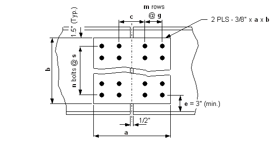
| Note: | Provide shim plates when connecting webs that differ in thickness by 1/8” or more. Use an equal number of shim plates on each side of the web. Uniformity of web plate thicknesses, which would eliminate the need for the minimum thickness of shim plate, should also be considered. |
| Web Dimensions | Splice Plates | Bolts | WT./Splice with 7/8" Bolts (lb) | |||||||
| Web Depth (in) |
Web Thickness (in) |
Plate Width a (in) |
Plate Depth b (in) |
# of rows (m) |
# of bolts per row (n) |
Spacing | ||||
| pitch (s) (in) | gage (g) (in) | center (c) (in) | clearance (e) (in) | |||||||
| 36 | 3/8 | 14 | 31 | 2 | 9 | 3.5 | 3 | 5 | 4 | 126.5 |
| 7/16 | 13.5 | 33 | 2 | 11 | 3 | 3 | 4.5 | 3 | 136.5 | |
| 38 | 3/8 | 14 | 35 | 2 | 9 | 4 | 3 | 5 | 3 | 138.4 |
| 7/16 | 14 | 34.5 | 2 | 10 | 3.5 | 3 | 5 | 3.25 | 140.7 | |
| 40 | 3/8 | 14 | 35 | 2 | 9 | 4 | 3 | 5 | 4 | 138.4 |
| 7/16 | 13.5 | 36 | 2 | 12 | 3 | 3 | 4.5 | 3.5 | 149.0 | |
| 1/2 | 19.5 | 35 | 3 | 9 | 4 | 3 | 4.5 | 4 | 196.4 | |
| 42 | 3/8 | 13.5 | 38 | 2 | 11 | 3.5 | 3 | 4.5 | 3.5 | 150.9 |
| 7/16 | 13.5 | 38 | 2 | 11 | 3.5 | 3 | 4.5 | 3.5 | 150.9 | |
| 1/2 | 13.5 | 39 | 2 | 13 | 3 | 3 | 4.5 | 3 | 161.4 | |
| 44 | 3/8 | 14 | 39 | 2 | 9 | 4.5 | 3 | 5 | 4 | 150.3 |
| 7/16 | 14 | 38 | 2 | 11 | 3.5 | 3 | 5 | 4.5 | 154.9 | |
| 1/2 | 13.5 | 39 | 2 | 13 | 3 | 3 | 4.5 | 4 | 161.4 | |
| 46 | 3/8 | 14 | 43 | 2 | 9 | 5 | 3 | 5 | 3 | 162.2 |
| 7/16 | 13.5 | 43 | 2 | 11 | 4 | 3 | 4.5 | 3 | 165.3 | |
| 1/2 | 13.5 | 42 | 2 | 14 | 3 | 3 | 4.5 | 3.5 | 173.8 | |
| 9/16 | 19 | 43 | 3 | 11 | 4 | 3 | 4 | 3 | 236.5 | |
| 48 | 3/8 | 14 | 43 | 2 | 9 | 5 | 3 | 5 | 4 | 162.2 |
| 7/16 | 14 | 43 | 2 | 11 | 4 | 3 | 5 | 4 | 169.8 | |
| 1/2 | 13.5 | 45 | 2 | 13 | 3.5 | 3 | 4.5 | 3 | 178.6 | |
| 9/16 | 19 | 43 | 3 | 11 | 4 | 3 | 4 | 4 | 236.5 | |
| Web Dimensions | Splice Plates | Bolts | WT./Splice with 7/8" Bolts (lb) | |||||||
| Web Depth (in) |
Web Thickness (in) |
Plate Width a (in) |
Plate Depth b (in) |
# of rows (m) |
# of bolts per row (n) |
Spacing | ||||
| pitch (s) (in) | gage (g) (in) | center (c) (in) | clearance (e) (in) | |||||||
| 50 | 3/8 | 14 | 43.5 | 2 | 10 | 4.5 | 3 | 5 | 4.75 | 167.5 |
| 7/16 | 13.5 | 47 | 2 | 12 | 4 | 3 | 4.5 | 3 | 180.5 | |
| 1/2 | 13.5 | 45 | 2 | 15 | 3 | 3 | 4.5 | 4 | 186.2 | |
| 9/16 | 19 | 47 | 3 | 12 | 4 | 3 | 4 | 3 | 258.3 | |
| 52 | 3/8 | 14 | 48 | 2 | 10 | 5 | 3 | 5 | 3.5 | 180.9 |
| 7/16 | 14 | 48 | 2 | 11 | 4.5 | 3 | 5 | 3.5 | 184.7 | |
| 1/2 | 13.5 | 48.5 | 2 | 14 | 3.5 | 3 | 4.5 | 3.25 | 192.4 | |
| 9/16 | 13 | 48 | 2 | 16 | 3 | 3 | 4 | 3.5 | 193.5 | |
| 5/8 | 19 | 48.5 | 3 | 14 | 3.5 | 3 | 4 | 3.25 | 275.8 | |
| 54 | 7/16 | 13.5 | 51 | 2 | 13 | 4 | 3 | 4.5 | 3 | 195.8 |
| 1/2 | 13.5 | 51 | 2 | 13 | 4 | 3 | 4.5 | 3 | 195.8 | |
| 9/16 | 13 | 51 | 2 | 17 | 3 | 3 | 4 | 3 | 205.6 | |
| 5/8 | 19 | 51 | 3 | 13 | 4 | 3 | 4 | 3 | 280.2 | |
| 56 | 7/16 | 14 | 53 | 2 | 11 | 5 | 3 | 5 | 3 | 199.6 |
| 1/2 | 13.5 | 52 | 2 | 15 | 3.5 | 3 | 4.5 | 3.5 | 206.3 | |
| 9/16 | 13 | 51 | 2 | 17 | 3 | 3 | 4 | 4 | 205.6 | |
| 5/8 | 19 | 52 | 3 | 15 | 3.5 | 3 | 4 | 3.5 | 295.6 | |
| 58 | 7/16 | 14 | 52.5 | 2 | 12 | 4.5 | 3 | 5 | 4.25 | 201.9 |
| 1/2 | 13.5 | 52 | 2 | 15 | 3.5 | 3 | 4.5 | 4.5 | 206.3 | |
| 9/16 | 13 | 54 | 2 | 18 | 3 | 3 | 4 | 3.5 | 217.7 | |
| 5/8 | 19 | 55 | 3 | 14 | 4 | 3 | 4 | 3 | 302.0 | |
| Web Dimensions | Splice Plates | Bolts | WT./Splice with 7/8" Bolts (lb) | |||||||
| Web Depth (in) |
Web Thickness (in) |
Plate Width a (in) |
Plate Depth b (in) |
# of rows (m) |
# of bolts per row (n) |
Spacing | ||||
| pitch (s) (in) | gage (g) (in) | center (c) (in) | clearance (e) (in) | |||||||
| 60 | 7/16 | 13.5 | 57 | 2 | 13 | 4.5 | 3 | 4.5 | 3 | 213.1 |
| 1/2 | 13.5 | 55.5 | 2 | 16 | 3.5 | 3 | 4.5 | 3.75 | 220.1 | |
| 9/16 | 13 | 54 | 2 | 18 | 3 | 3 | 4 | 4.5 | 217.7 | |
| 5/8 | 19 | 57 | 3 | 13 | 4.5 | 3 | 4 | 3 | 304.4 | |
| 62 | 7/16 | 14 | 57 | 2 | 13 | 4.5 | 3 | 5 | 4 | 219.1 |
| 1/2 | 13.5 | 59 | 2 | 15 | 4 | 3 | 4.5 | 3 | 226.4 | |
| 9/16 | 13 | 59 | 2 | 17 | 3.5 | 3 | 4 | 3 | 227.7 | |
| 5/8 | 19 | 59 | 3 | 15 | 4 | 3 | 4 | 3 | 323.9 | |
| 11/16 | 19 | 59 | 3 | 17 | 3.5 | 3 | 4 | 3 | 335.3 | |
| 64 | 7/16 | 13.5 | 59 | 2 | 15 | 4 | 3 | 4.5 | 4 | 226.4 |
| 1/2 | 13.5 | 59 | 2 | 17 | 3.5 | 3 | 4.5 | 4 | 234.0 | |
| 9/16 | 13 | 57 | 2 | 19 | 3 | 3 | 4 | 5 | 229.8 | |
| 5/8 | 19 | 59 | 3 | 15 | 4 | 3 | 4 | 4 | 323.9 | |
| 11/16 | 19 | 59 | 3 | 17 | 3.5 | 3 | 4 | 4 | 335.3 | |
| 66 | 1/2 | 13.5 | 63 | 2 | 16 | 4 | 3 | 4.5 | 3 | 241.7 |
| 9/16 | 13 | 62.5 | 2 | 18 | 3.5 | 3 | 4 | 3.25 | 241.2 | |
| 5/8 | 13 | 63 | 2 | 21 | 3 | 3 | 4 | 3 | 254.0 | |
| 11/16 | 19 | 63 | 3 | 16 | 4 | 3 | 4 | 3 | 345.8 | |
| 68 | 1/2 | 13.5 | 63 | 2 | 16 | 4 | 3 | 4.5 | 4 | 241.7 |
| 9/16 | 13 | 63 | 2 | 21 | 3 | 3 | 4 | 4 | 254.0 | |
| 5/8 | 19 | 63 | 3 | 16 | 4 | 3 | 4 | 4 | 345.8 | |
| 11/16 | 19 | 62.5 | 3 | 18 | 3.5 | 3 | 4 | 4.25 | 355.1 | |
| 70 | 1/2 | 13.5 | 67 | 2 | 17 | 4 | 3 | 4.5 | 3 | 257.0 |
| 9/16 | 13 | 66 | 2 | 19 | 3.5 | 3 | 4 | 3.5 | 254.7 | |
| 5/8 | 13 | 66 | 2 | 22 | 3 | 3 | 4 | 3.5 | 266.1 | |
| 11/16 | 19 | 67 | 3 | 17 | 4 | 3 | 4 | 3 | 367.6 | |
| 72 | 1/2 | 13.5 | 67 | 2 | 17 | 4 | 3 | 4.5 | 4 | 257.0 |
| 9/16 | 13 | 66 | 2 | 22 | 3 | 3 | 4 | 4.5 | 266.1 | |
| 5/8 | 13 | 69 | 2 | 23 | 3 | 3 | 4 | 3 | 278.2 | |
| 11/16 | 19 | 67 | 3 | 17 | 4 | 3 | 4 | 4 | 367.6 | |
| 74 | 1/2 | 13.5 | 71 | 2 | 18 | 4 | 3 | 4.5 | 3 | 272.2 |
| 9/16 | 13 | 69.5 | 2 | 20 | 3.5 | 3 | 4 | 3.75 | 268.2 | |
| 5/8 | 13 | 69 | 2 | 23 | 3 | 3 | 4 | 4 | 278.2 | |
| 11/16 | 19 | 71 | 3 | 18 | 4 | 3 | 4 | 3 | 389.5 | |
| 76 | 9/16 | 13 | 73 | 2 | 21 | 3.5 | 3 | 4 | 3 | 281.6 |
| 5/8 | 13 | 72 | 2 | 24 | 3 | 3 | 4 | 3.5 | 290.3 | |
| 11/16 | 19 | 71 | 3 | 18 | 4 | 3 | 4 | 4 | 389.5 | |
| 78 | 9/16 | 13 | 73 | 2 | 21 | 3.5 | 3 | 4 | 4 | 281.6 |
| 5/8 | 13 | 72 | 2 | 24 | 3 | 3 | 4 | 4.5 | 290.3 | |
| 11/16 | 19 | 75 | 3 | 17 | 4.5 | 3 | 4 | 3 | 400.0 | |
| 80 | 9/16 | 13 | 76.5 | 2 | 22 | 3.5 | 3 | 4 | 3.25 | 295.1 |
| 5/8 | 13 | 75 | 2 | 25 | 3 | 3 | 4 | 4 | 302.4 | |
| 11/16 | 19 | 75 | 3 | 19 | 4 | 3 | 4 | 4 | 411.4 | |
| 82 | 9/16 | 13 | 76.5 | 2 | 22 | 3.5 | 3 | 4 | 4.25 | 295.1 |
| 5/8 | 13 | 75 | 2 | 25 | 3 | 3 | 4 | 5 | 302.4 | |
| 11/16 | 19 | 79 | 3 | 20 | 4 | 3 | 4 | 3 | 433.2 | |
| 84 | 9/16 | 13 | 80 | 2 | 23 | 3.5 | 3 | 4 | 3.5 | 308.6 |
| 5/8 | 13 | 78 | 2 | 26 | 3 | 3 | 4 | 4.5 | 314.5 | |
| 11/16 | 13 | 81 | 2 | 27 | 3 | 3 | 4 | 3 | 326.5 | |
| 86 | 5/8 | 13 | 81 | 2 | 27 | 3 | 3 | 4 | 4 | 326.5 |
| 11/16 | 19 | 79 | 3 | 20 | 4 | 3 | 4 | 5 | 433.2 | |
| 88 | 5/8 | 13 | 81 | 2 | 27 | 3 | 3 | 4 | 5 | 326.5 |
| 11/16 | 13 | 84 | 2 | 28 | 3 | 3 | 4 | 3.5 | 338.6 | |
| 90 | 5/8 | 13 | 87 | 2 | 25 | 3.5 | 3 | 4 | 3 | 335.5 |
| 11/16 | 13 | 87 | 2 | 29 | 3 | 3 | 4 | 3 | 350.7 | |
| 92 | 5/8 | 13 | 84 | 2 | 28 | 3 | 3 | 4 | 5.5 | 338.6 |
| 11/16 | 19 | 88.5 | 3 | 20 | 4.5 | 3 | 4 | 3.25 | 471.6 | |
| 94 | 5/8 | 13 | 90.5 | 2 | 26 | 3.5 | 3 | 4 | 3.25 | 349.0 |
| 11/16 | 13 | 90 | 2 | 30 | 3 | 3 | 4 | 3.5 | 362.8 | |
| 96 | 5/8 | 13 | 90 | 2 | 30 | 3 | 3 | 4 | 4.5 | 362.8 |
| 11/16 | 13 | 93 | 2 | 31 | 3.5 | 3 | 4 | 3 | 374.9 | |
751.14.3.4 Wide Flange Splice Tables
Note: In the 15th edition of the AISC Steel Construction Manual (2017) the k1 values for many w-shapes increased. The k1 dimension is the distance between the centerline of web and the toe of the fillet into the flange. The inner plates below were designed before this change and as designed may encroach on the toe of the flange fillet. Before using one of the tabulated wide flange splice designs the inner plate shall be checked to ensure it does not encroach on the toe of the flange fillet.
27” Wide Flange Beams
ASTM A709, Grade 50 and 50W Webs, Grade 50 and 50W Splices
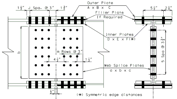
| Note: | Bottom flange splice plates are the same as the top. Provide shim plates when connecting webs that differ in thickness by 1/8” or more. Use an equal number of shim plates on each side of the web. Use the smallest beam size to determine splice details. |
| Size of Beam |
Filler Plate Thick. |
Outer Plate | Inner Plates | Web Splice Plates | Total Number of Bolts |
Weight (lb) | ||||||||
| A (in) |
B (in) |
C (in) |
D (in) |
E (in) |
F (in) |
J | a (in) |
b (in) |
c (in) |
m | ||||
| W27x84** | < 1/4" | 10 | 0.375 | 18.5 | 3.5 | 0.5 | 18.5 | 2 | 19.5 | 21.75 | 0.4375 | 3 | 60 | 238.3 |
| other | 10 | 0.375 | 24.5 | 3.5 | 0.5 | 24.5 | 3 | 19.5 | 21.75 | 0.4375 | 3 | 68 | 270.6 | |
| W27x94** | < 1/4" | 10 | 0.5 | 24.5 | 3.5 | 0.625 | 24.5 | 3 | 25.5 | 21.75 | 0.5 | 4 | 80 | 363.5 |
| other | 10 | 0.5 | 30.5 | 3.5 | 0.625 | 30.5 | 4 | 25.5 | 21.75 | 0.5 | 4 | 88 | 403.0 | |
| W27x102** | < 1/4" | 10 | 0.5 | 24.5 | 3.5 | 0.625 | 24.5 | 3 | 25.5 | 21.75 | 0.5625 | 4 | 80 | 383.2 |
| other | ----------------------------------------- Design by Hand ------------------------------------------ | |||||||||||||
| W27x114** | < 1/4" | 10 | 0.5 | 24.5 | 3.5 | 0.75 | 24.5 | 3 | 25.5 | 21.75 | 0.5625 | 4 | 80 | 395.4 |
| other | ----------------------------------------- Design by Hand ------------------------------------------ | |||||||||||||
| W27x129** | < 1/4" | 10 | 0.5625 | 30.5 | 3.5 | 0.875 | 30.5 | 4 | 31.5 | 21.75 | 0.6875 | 5 | 100 | 565.4 |
| other | ----------------------------------------- Design by Hand ------------------------------------------ | |||||||||||||
| ** Denotes flange widths less than 12” where P/S Panel placement should be thoroughly investigated. | ||||||||||||||
30” Wide Flange Beams
ASTM A709, Grade 50 and 50W Webs, Grade 50 and 50W Splices
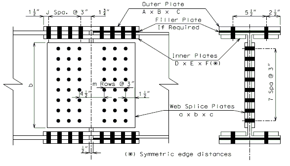
| Note: | Bottom flange splice plates are the same as the top. Provide shim plates when connecting webs that differ in thickness by 1/8” or more. Use an equal number of shim plates on each side of the web. Use the smallest beam size to determine splice details. |
| Size of Beam |
Filler Plate Thick. |
Outer Plate | Inner Plates | Web Splice Plates | Total Number of Bolts |
Weight (lb) | ||||||||
| A (in) |
B (in) |
C (in) |
D (in) |
E (in) |
F (in) |
J | a (in) |
b (in) |
c (in) |
m | ||||
| W30x90** | < 1/4" | 10.5 | 0.375 | 18.5 | 3.5 | 0.5 | 18.5 | 2 | 19.5 | 24 | 0.4375 | 3 | 72 | 262.6 |
| other | 10.5 | 0.375 | 30.5 | 3.5 | 0.5 | 30.5 | 4 | 19.5 | 24 | 0.4375 | 3 | 88 | 328.4 | |
| W30x99** | < 1/4" | 10.5 | 0.375 | 24.5 | 3.5 | 0.5 | 24.5 | 3 | 19.5 | 24 | 0.5 | 3 | 80 | 312.0 |
| other | 10.5 | 0.375 | 30.5 | 3.5 | 0.5 | 30.5 | 4 | 19.5 | 24 | 0.5 | 3 | 88 | 345.0 | |
| W30x108** | < 1/4" | 10.5 | 0.5 | 24.5 | 3.5 | 0.625 | 24.5 | 3 | 19.5 | 24 | 0.5 | 3 | 80 | 342.4 |
| other | 10.5 | 0.5 | 36.5 | 3.5 | 0.625 | 36.5 | 5 | 19.5 | 24 | 0.5 | 3 | 96 | 423.1 | |
| W30x116** | < 1/4" | 10.5 | 0.5 | 30.5 | 3.5 | 0.75 | 30.5 | 4 | 25.5 | 24 | 0.5625 | 4 | 104 | 475.7 |
| other | 10.5 | 0.5 | 30.5 | 3.5 | 0.75 | 30.5 | 4 | 25.5 | 24 | 0.5625 | 4 | 104 | 475.7 | |
| W30x124** | < 1/4" | 10.5 | 0.5 | 30.5 | 3.5 | 0.75 | 30.5 | 4 | 25.5 | 24 | 0.5625 | 4 | 104 | 475.7 |
| other | 10.5 | 0.5 | 30.5 | 3.5 | 0.75 | 30.5 | 4 | 25.5 | 24 | 0.5625 | 4 | 104 | 475.7 | |
| W30x132** | < 1/4" | 10.5 | 0.5 | 30.5 | 3.5 | 0.75 | 30.5 | 4 | 25.5 | 24 | 0.625 | 4 | 104 | 497.4 |
| other | ----------------------------------------- Design by Hand ------------------------------------------ | |||||||||||||
| W30x148** | < 1/4" | 10.5 | 0.625 | 36.5 | 3.5 | 0.875 | 36.5 | 5 | 25.5 | 24 | 0.625 | 4 | 112 | 586.0 |
| other | ----------------------------------------- Design by Hand ------------------------------------------ | |||||||||||||
| ** Denotes flange widths less than 12” where P/S Panel placement should be thoroughly investigated. | ||||||||||||||
33” Wide Flange Beams
ASTM A709, Grade 50 and 50W Webs, Grade 50 and 50W Splices
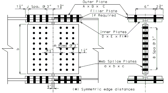
| Note: | Bottom flange splice plates are the same as the top. Provide shim plates when connecting webs that differ in thickness by 1/8” or more. Use an equal number of shim plates on each side of the web. Use the smallest beam size to determine splice details. |
| Size of Beam |
Filler Plate Thick. |
Outer Plate | Inner Plates | Web Splice Plates | Total Number of Bolts |
Weight (lb) | ||||||||
| A (in) |
B (in) |
C (in) |
D (in) |
E (in) |
F (in) |
J | a (in) |
b (in) |
c (in) |
m | ||||
| W33x118** | < 1/4" | 11.5 | 0.5 | 30.5 | 3.5 | 0.625 | 30.5 | 4 | 19.5 | 27 | 0.5 | 3 | 94 | 413.7 |
| other | 11.5 | 0.5 | 36.5 | 3.5 | 0.625 | 36.5 | 5 | 19.5 | 27 | 0.5 | 3 | 102 | 455.8 | |
| W33x130** | < 1/4" | 11.5 | 0.5 | 30.5 | 3.5 | 0.75 | 30.5 | 4 | 25.5 | 27 | 0.5625 | 4 | 112 | 516.3 |
| other | 11.5 | 0.5 | 42.5 | 3.5 | 0.75 | 42.5 | 6 | 25.5 | 27 | 0.5625 | 4 | 128 | 606.4 | |
| W33x141** | < 1/4" | 11.5 | 0.625 | 36.5 | 3.5 | 0.875 | 36.5 | 5 | 25.5 | 27 | 0.5625 | 4 | 120 | 609.2 |
| other | 11.5 | 0.625 | 42.5 | 3.5 | 0.875 | 42.5 | 6 | 25.5 | 27 | 0.5625 | 4 | 128 | 662.1 | |
| W33x152** | < 1/4" | 11.5 | 0.625 | 36.5 | 3.5 | 0.875 | 36.5 | 5 | 25.5 | 27 | 0.625 | 4 | 120 | 633.6 |
| other | ----------------------------------------- Design by Hand ------------------------------------------ | |||||||||||||
| W33x169** | < 1/4" | 11.5 | 0.625 | 36.5 | 3.5 | 1 | 36.5 | 5 | 25.5 | 27 | 0.625 | 4 | 120 | 651.7 |
| other | ----------------------------------------- Design by Hand ------------------------------------------ | |||||||||||||
| ** Denotes flange widths less than 12” where P/S Panel placement should be thoroughly investigated. | ||||||||||||||
33” Wide Flange Beams
ASTM A709, Grade 50 and 50W Webs, Grade 50 and 50W Splices
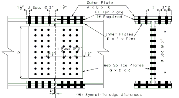
| Note: | Bottom flange splice plates are the same as the top. Provide shim plates when connecting webs that differ in thickness by 1/8” or more. Use an equal number of shim plates on each side of the web. Use the smallest beam size to determine splice details. |
| Size of Beam |
Filler Plate Thick. |
Outer Plate | Inner Plates | Web Splice Plates | Total Number of Bolts |
Weight (lb) | ||||||||||
| A (in) |
B (in) |
C (in) |
D (in) |
E (in) |
F (in) |
G (in) |
I (in) |
J | a (in) |
b (in) |
c (in) |
m | ||||
| W33x201 | < 1/4" | 15.75 | 0.625 | 24.5 | 6 | 0.875 | 24.5 | 2 | 5.75 | 3 | 24.5 | 27 | 0.6875 | 4 | 136 | 669.8 |
| other | ------------------------------------------------------- Design by Hand -------------------------------------------------------- | |||||||||||||||
| W33x221 | < 1/4" | 15.75 | 0.75 | 30.5 | 6 | 0.875 | 30.5 | 2 | 5.75 | 4 | 30.5 | 27 | 0.75 | 5 | 170 | 897.7 |
| other | ------------------------------------------------------- Design by Hand -------------------------------------------------------- | |||||||||||||||
36” Wide Flange Beams
ASTM A709, Grade 50 and 50W Webs, Grade 50 and 50W Splices
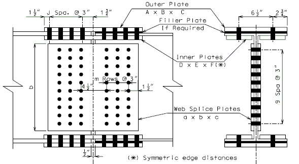
| Note: | Bottom flange splice plates are the same as the top. Provide shim plates when connecting webs that differ in thickness by 1/8” or more. Use an equal number of shim plates on each side of the web. Use the smallest beam size to determine splice details. |
| Size of Beam |
Filler Plate Thick. |
Outer Plate | Inner Plates | Web Splice Plates | Total Number of Bolts |
Weight (lb) | ||||||||
| A (in) |
B (in) |
C (in) |
D (in) |
E (in) |
F (in) |
J | a (in) |
b (in) |
c (in) |
m | ||||
| W36x135 | < 1/4" | 12 | 0.625 | 30.5 | 4 | 0.625 | 30.5 | 4 | 19.5 | 30 | 0.5 | 3 | 100 | 477.1 |
| other | 12 | 0.625 | 42.5 | 4 | 0.625 | 42.5 | 6 | 19.5 | 30 | 0.5 | 3 | 116 | 577.4 | |
| W36x150 | < 1/4" | 12 | 0.625 | 36.5 | 4 | 0.75 | 36.5 | 5 | 25.5 | 30 | 0.5625 | 4 | 128 | 645.1 |
| other | 12 | 0.625 | 42.5 | 4 | 0.75 | 42.5 | 6 | 25.5 | 30 | 0.5625 | 4 | 136 | 698.6 | |
| W36x160 | < 1/4" | 12 | 0.625 | 36.5 | 4 | 0.875 | 36.5 | 5 | 25.5 | 30 | 0.5625 | 4 | 128 | 665.8 |
| other | ----------------------------------------- Design by Hand ------------------------------------------ | |||||||||||||
| W36x170 | < 1/4" | 12 | 0.625 | 36.5 | 4 | 0.875 | 36.5 | 5 | 25.5 | 30 | 0.5625 | 4 | 128 | 665.8 |
| other | ----------------------------------------- Design by Hand ------------------------------------------ | |||||||||||||
| W36x182 | < 1/4" | 12 | 0.75 | 42.5 | 4 | 1 | 42.5 | 6 | 25.5 | 30 | 0.625 | 4 | 136 | 810.1 |
| other | ----------------------------------------- Design by Hand ------------------------------------------ | |||||||||||||
| W36x194 | < 1/4" | 12 | 0.75 | 42.5 | 4 | 1 | 42.5 | 6 | 25.5 | 30 | 0.625 | 4 | 136 | 810.1 |
| other | ----------------------------------------- Design by Hand ------------------------------------------ | |||||||||||||
40” Wide Flange Beams
ASTM A709, Grade 50 and 50W Webs, Grade 50 and 50W Splices
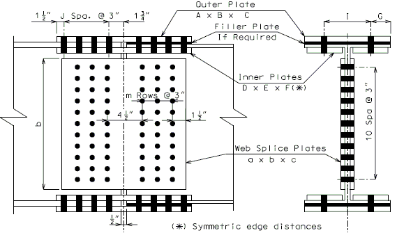
| Note: | Bottom flange splice plates are the same as the top. Provide shim plates when connecting webs that differ in thickness by 1/8” or more. Use an equal number of shim plates on each side of the web. Use the smallest beam size to determine splice details. |
| Size of Beam |
Filler Plate Thick. |
Outer Plate | Inner Plates | Web Splice Plates | Total Number of Bolts |
Weight (lb) | ||||||||||
| A (in) |
B (in) |
C (in) |
D (in) |
E (in) |
F (in) |
G (in) |
I (in) |
J | a (in) |
b (in) |
c (in) |
m | ||||
| W40x149** | < 1/4" | 11.75 | 0.625 | 30.5 | 3.5 | 0.75 | 30.5 | 2.625 | 6.5 | 4 | 19.5 | 33 | 0.4375 | 3 | 106 | 478.2 |
| other | 11.75 | 0.625 | 42.5 | 3.5 | 0.75 | 42.5 | 2.625 | 6.5 | 6 | 19.5 | 33 | 0.4375 | 3 | 122 | 579.1 | |
| W40x167** | < 1/4" | 11.75 | 0.75 | 36.5 | 3.5 | 1 | 36.5 | 2.5 | 6.75 | 5 | 25.5 | 33 | 0.5 | 4 | 136 | 695.1 |
| other | 11.75 | 0.75 | 48.5 | 3.5 | 1 | 48.5 | 2.5 | 6.75 | 7 | 25.5 | 33 | 0.5 | 4 | 152 | 818.0 | |
| W40x183** | < 1/4" | 11.75 | 0.75 | 42.5 | 3.5 | 1.125 | 42.5 | 2.5 | 6.75 | 6 | 25.5 | 33 | 0.5 | 4 | 144 | 777.6 |
| other | 11.75 | 0.75 | 42.5 | 3.5 | 1.125 | 42.5 | 2.5 | 6.75 | 6 | 25.5 | 33 | 0.5 | 4 | 144 | 777.6 | |
| W40x199*** | < 1/4" | 15.75 | 0.625 | 24.5 | 5.75 | 0.75 | 24.5 | 2 | 6.25 | 3 | 25.5 | 33 | 0.5 | 4 | 152 | 639.6 |
| other | ------------------------------------------------------- Design by Hand -------------------------------------------------------- | |||||||||||||||
| W40x211** | < 1/4" | 11.75 | 0.75 | 48.5 | 3.5 | 1.25 | 48.5 | 2.5 | 6.75 | 7 | 25.5 | 33 | 0.625 | 4 | 152 | 925.7 |
| other | ------------------------------------------------------- Design by Hand -------------------------------------------------------- | |||||||||||||||
| W40x215*** | < 1/4" | 15.75 | 0.625 | 30.5 | 5.75 | 0.875 | 30.5 | 2 | 6.25 | 4 | 25.5 | 33 | 0.5625 | 4 | 168 | 772.4 |
| other | ------------------------------------------------------- Design by Hand -------------------------------------------------------- | |||||||||||||||
| ** Denotes flange widths less than 12” where P/S Panel placement should be thoroughly investigated. | ||||||||||||||||
| *** Outer splice plates with widths of 15 3/4” have 4 rows of flange bolts in lieu of 2 rows per drawing. | ||||||||||||||||
751.14.3.5 Shop Welded Splices
Reference: LRFD Figure 6.13.6.2-1
| The following details and note shall be provided on all plate girder bridges. | |
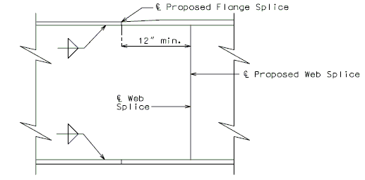
| |
| Welded Shop web Splice | |
|---|---|
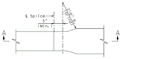
| |
| Plan | |
| 2'-0" Radius Transition | |
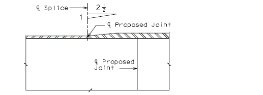
| |
| Section A-A | |
| Welded Shop Flange Splice | |
| Note: | Welded shop web and flange splices may be permitted when detailed on the shop drawings and approved by the engineer. No additional payment will be made for optional welded shop web and flange splices. |
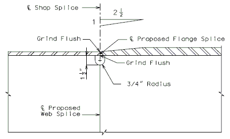
| |
| Welded Shop Splice | |
|---|---|
| Notes: | See Structural Project Manager before utilizing this detail. |
| It is recommended to avoid this detail if possible. | |
751.14.4 Composite Design
751.14.4.1 General
Overview
The pitch of shear connectors shall be determined to satisfy the fatigue limit state, and the resulting number of shear connectors shall not be less than the number required to satisfy the strength limit state.
Cross-section properties are based on the transformed short-term composite section. Cross-section properties of the composite section shall include concrete slab and steel section. Longitudinal deck reinforcement shall not be considered to be a part of the composite section. Cross-section properties of the non-composite section shall include the steel section only. Negative flexure regions in horizontally curved girders may include the steel reinforcement in the composite section.
The stresses of composite girders and slab shall be computed using the composite cross-section properties and shall be consistent with the properties of the various materials used. The ratio of modulus of elasticity of steel to that of concrete, , shall be taken to be 8 when using deck concrete with = 4 KSI.
The effective flange widths for calculating composite sections for interior and exterior girders should be determined by LRFD 4.6.2.6 prior to beginning shear connector design. In order to have a uniform and conservative shear connector design for all girders, the smaller effective flange width, between the interior and exterior girders, should only be used to locate the acceptable areas for placement of additional connectors near point of dead load contraflexure. The larger effective flange width should be used in all other calculations.
An effective slab thickness shall be used for composite design by deducting from the actual slab thickness a 1” integral, sacrificial wearing surface.
New Bridges or Replacement of Existing Superstructures
The regions of the bridge subjected to positive flexure are to be designed as composite and the regions subjected to negative flexure are to be designed as non-composite. Simple span composite bridges shall be provided with shear connectors throughout the length of the span. Continuous composite bridges are to be designed with shear connectors provided in the positive flexure regions only, with additional connectors required in the regions of permanent load contraflexure. Horizontally curved girders require shear connectors throughout the girder length.
For the initial girder design, composite/noncomposite regions can be approximately assumed as:
Redeckings
If existing bridge is partially composite, then leave as partially composite unless making full-length composite will reduce or eliminate a load posting subject to Structural Project Manager or Structural Liaison Engineer approval. If the existing bridge is not composite, then make it full-length composite since this will give the maximum capacity of the bridge for the next service life cycle. This guidance applies to either LRFD or LFD redecking designs. Shear connector design should follow same design code used for redecking.
Design Loading
The girder shear force range due to fatigue loading, , should be determined from structural analysis prior to beginning shear connector design. The shear force range is the difference in the minimum and maximum shear force envelopes at any point. For design, use the average shear force range over the effective span (i.e. between contraflexure points). For horizontally curved girders the lateral component of the fatigue force range should be considered.
The stress range in the longitudinal reinforcement due to fatigue loading, , should be determined prior to beginning shear stud design. In lieu of more accurate computation, may be assumed to be 10 ksi.
- Note: This assumption is not provided by AASHTO LRFD, but is held over from AASHTO LFD Specifications.
Other Considerations
Shear connectors shall not be placed on the flange splice plates. Maintain at least 3” from end of splice plate to nearest connector for fabrication purposes.
The effect of the shear connector on the fatigue resistance of the flange shall be investigated using the provisions of LRFD 6.6.1.2.
Note: All spacing dimensions are measured to center of shear connector
751.14.4.2 Shear Connector Limits
Shear Connector Proportions
Shear connector height, , shall satisfy the following cover and deck penetration provisions:
Minimum shear connector penetration into deck:
- For cast in place deck: 2 in.
- For prestressed panel option: minimum penetration to top of panel
Minimum concrete clear cover over shear connectors = 3 in.
Choose a shear connector height that is acceptable for both SIP and CIP deck options. Use 1 in. increments for selecting shear connector height. Minimum shear connector height = 4 in.
Shear connector diameter, , shall satisfy:
Recommended shear connector diameters, :
- 3/4 in.
- 7/8 in.
Shear Connector Configuration
The following transverse spacing provisions must be satisfied when determining the number of shear connectors per row, :
Minimum transverse shear connector spacing:
- Preferred minimum: 4d
- Absolute minimum: 2 1/4 in.
Minimum distance between edge of top flange and nearest shear connector:
- For cast in place deck: 1 1/2 in.
- For prestressed panel option: 4 1/4 in.
Shear connectors shall be placed by units. A shear connector unit refers to all shear connectors in a given cross-section, spaced transversely across the top flange. Multiple shear connectors per unit may be used if spacing and clearances allow. For horizontally curved girders, when practical, a consistent unit layout and pitch shall be used throughout the span.
Shear Connector Spacing
If it becomes impractical to place the number of shear connectors required by ultimate strength in the specified distance (structures with span ratios greater than 1.5); base the number and spacing of shear connectors on the fatigue analysis only.
For a typical 3-span bridge, the shear connector units can be approximately arranged as below:
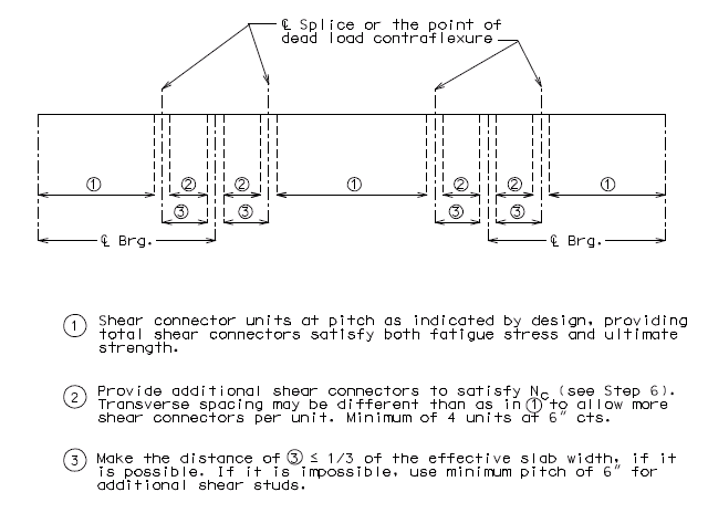
751.14.4.3 Fatigue Design
Fatigue Resistance
The number of fatigue cycles for design, N, shall be determined as:
Where:
| = number of stress range cycles per truck passage | |
| = single lane average daily truck traffic |
For longitudinal members not near interior supports*:
| = 2.0 for spans ≤ 40 ft. | |
| = 1.0 for spans > 40 ft. |
- See LRFD Table 6.6.1.2.5-2 for other situations.
In absence of better information, the single lane average daily truck traffic shall be taken as:
Where:
| = number of trucks per day in one direction, averaged over the design life | |
| = fraction of truck traffic in a single lane |
| Number of Lanes Available to Trucks |
|
| 1 | 1.00 |
| 2 | 0.85 |
| 3 or more | 0.80 |
The shear fatigue resistance of an individual shear connector, , is determined as follows:
Where:
| = shear fatigue factor | |
| = 34.5 – 4.28Log(N) |
Pitch
Straight Girders
The maximum pitch of shear connectors along the longitudinal axis required to satisfy the fatigue limit state, , is determined as:
Where:
| = number of shear connectors per unit | |
| = moment of inertia of the short-term composite section | |
| = vertical shear force range due to fatigue loading | |
| = first moment of the transformed area of the slab about the neutral axis of the short-term composite section |
Maximum pitch = 24 in.
Preferred minimum pitch = 6 in.
Absolute minimum pitch = 6d
Use 1 in. increments for pitch.
Horizontally Curved Girders (see Analysis of Horizontally Curved Girders)
Horizontally curved girders will receive a lateral fatigue component introduced by the diaphragms. The above equation for pitch shall be modified as follows:
Where includes the longitudinal and radial fatigue shear ranges:
For bridge skews
For birdge skews
Where:
| = area of bottom flange | |
| = range of longitudinal fatigue stress range in bottom flange | |
| = distance between brace points | |
| = effective length of deck, 24” – end supports, 48” elsewhere | |
| = radius of girder; use minimum if radius transitions inside girder panel | |
| = net range of diaphragm force at the top flange. |
Note: For the purpose of the above calculations the bridge skew shall be taken as the maximum bent skew along the length of the bridge.
751.14.4.4 Strength Design
Resistance
The total nominal horizontal shear force between the point of maximum positive moment and each adjacent point of zero moment, Vh, is determined as:
Where:
| = 28 day compressive strength of deck concrete | |
| = effective flange width | |
| = effective slab thickness | |
| = yield strength of web | |
| = web depth | |
| = web thickness | |
| = yield strength of tension flange | |
| = width of tension flange | |
| = thickness of tension flange | |
| = yield strength of compression flange | |
| = width of compression flange | |
| = thickness of compression flange |
The nominal shear resistance of a single shear connector embedded in a concrete slab, , is calculated as follows:
Where:
| = cross sectional area of a shear connector | |
| = modulus of elasticity of deck concrete | |
| = tensile strength of shear connector steel |
The factored resistance of a single shear connector, , shall be determined as:
Where
| = resistance factor for shear connectors = 0.85 |
| – Factored Resistance of One Shear Connector | |
| Stud Diameter | |
| 3/4" | 22.5 |
| 7/8" | 30.7 |
The minimum number of shear connectors required for strength in each region, , shall be computed:
Regions are defined as the areas between points of zero moment and adjacent points of maximum positive moment. is the minimum number of shear connectors that must be placed in each region to satisfy the strength limit state.
Additional Connectors
The number of additional connectors to be placed in the region of permanent load contraflexure, , shall be:
Where:
| = total area of deck reinforcement within the effective flange width | |
| = stress range in the longitudinal reinforcement due to fatigue loading |
Minimum number of additional connectors = 4 units at 6d.
The additional shear connectors shall be placed within a distance of 1/3 of the minimum effective flange width on each side of the point of permanent load contraflexure.
If it is not possible to place additional connectors within b/3 from the point of dead load contraflexure, the additional connectors shall be placed as close to the contraflexure point as practical, using the minimum pitch of 6d.
Horizontally Curved Girders
Girders that are analyzed for curvature effects require shear connectors to be placed throughout the bridge. The provision for additional shear connector placement does not apply. Horizontally curved girders require separate analyses for regions near the end of the bridge and regions near interior supports. They also require a lateral shear force to be considered as shown below.
End of Bridge - Region:
Where:
| = lateral shear force | ||
| = arc length between end of girder and location of maximum positive moment | ||
| = minimum radius over arc length, . | ||
Near interior support – Region
Where:
| for section over pier | |||
| = lateral shear force near an interior support | |||
| = arc length between point of maximum positive moment and interior support | |||
| = minimum girder radius over length, . | |||
751.14.4.5 Shear Connector Details
| Minimum Flange Width For Given Rows of Studs (in.) (For decks utilizing prestressed panels) |
Weight in Place Per 100 Studs (lbs) | |||||||
| # of Studs per unit, n |
Absolute Min. |
Preferred Min. | Stud Dia. | 4" | 5" | 6" | 7" | |
| 3/4" dia. | 7/8" dia. | 3/4" | 63 | 75 | 88 | 100 | ||
| 2 | 10.75 | 11.50 | 12.00 | |||||
| 3 | 13.00 | 14.50 | 15.50 | 7/8" | 81 | 98 | 115 | 132 |
| 4 | 15.25 | 17.50 | 19.00 | |||||
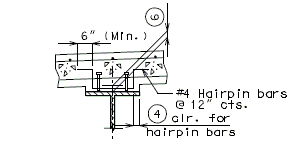
| ||

|
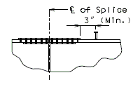
| |
| Section Thru Haunch | Clearance at Expansion Device |
Clearance at Splice Plate |
|---|
Shear Connector Unit
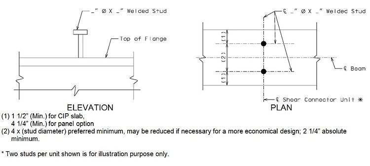
P/C P/S Panel Forms on Steel Structures
Evaluate the viability of the use of P/S panels on tangent and curved structures on a case by case basis and use or include as an option to a CIP slab where deemed appropriate.
Whenever panels are used, the minimum top flange width shall be 12" for plate girders and 10" for wide flange beams.
Steel girders shall be cambered when using P/S Panels. Minimum joint filler thickness is 1", except over splice plates, in which case use 1/4" minimum. Maximum joint filler thickness is 2", except over splice plates, in which case use 1".
Shear connectors shall have a minimum height equal to the top of panel.
Shear connectors shall be spaced by units and shear connectors in each unit shall be placed along centerline () of girder. On wide flange widths, two lines of connectors may be used if spacings and clearances allow.
Additional shear connectors, Nac, at point of contraflexure may be placed in units normal to centerline of girder as space allows or in a single row along centerline of girder as shown below:
P/S strands shall extend 3" minimum and 6" maximum past edge of precast prestressed panel and not closer than 1" to the adjacent panels.
Panel end at splices shall be notched to avoid bolt heads as shown below:
![]() 3/4" min. wide bearing edge for panel at splice, typ.
3/4" min. wide bearing edge for panel at splice, typ.
![]() 4 x (Stud diameter) preferred minimum, may be reduced if necessary for a more economical design; 2-1/4" absolute minimum.
4 x (Stud diameter) preferred minimum, may be reduced if necessary for a more economical design; 2-1/4" absolute minimum.
* In order to meet ![]() and
and ![]() above, it is necessary to have an edge bolt distance of 2" or greater for splice plate.
above, it is necessary to have an edge bolt distance of 2" or greater for splice plate.
Minimum joint filler thickness is 1" except over splice plates in which case use 1/4" minimum. Use 3/4" joint filler width for panels over splice plates. When joint filler is less than 1/2" thick over splice plate, the contractor is required to make the width of joint filler at splice the same width as panel on splice.
Maximum difference in top of flange thickness should be checked so that joint filler thickness does not exceed 2".
751.14.5 Details
751.14.5.1 Bearing Stiffeners
Refer to EPG 751.14.5.10 for weld design and detail guidance. Refer to EPG 751.14.5.5 Transverse Stiffeners for beveled plate guidance for unequal flange widths.
The preferred welded connection to flange is more prone to fatigue than the bolted connection. Girder shall be sized to reduce fatigue stresses to allow for preferred detail. If resizing is impractical the bolted connection shall be used.
Size bearing stiffener plate by design (1/2" thick minimum). See EPG 751.14.2.6 Other Requirements.
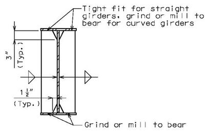
No Attachments
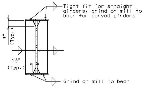
Diaphragms or Cross Frames Attached
(Preferred detail)
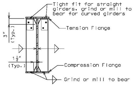
Cross Frames Attached
(Optional detail1)
1 Holes in the tension flange restricts girder design in accordance with EPG 751.14.2.2 Analysis Methods
Locations
Refer to EPG 751.14.5.10 for weld design and detail guidance.
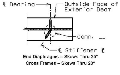
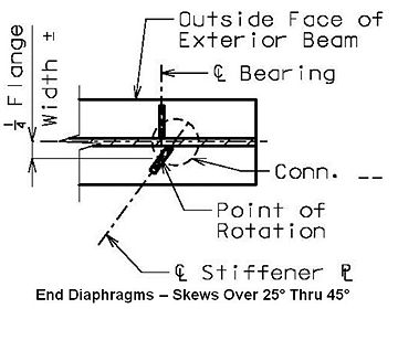
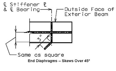
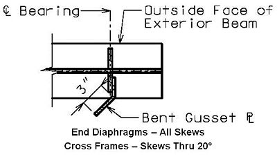
Welds for Optional Stiffener Locations
Refer to EPG 751.14.5.10 for weld design and detail guidance.
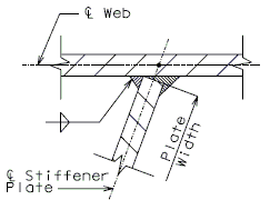
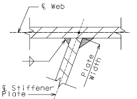
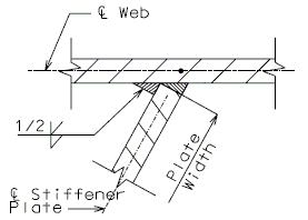
Connection Angle Details for Optional Stiffener Connection
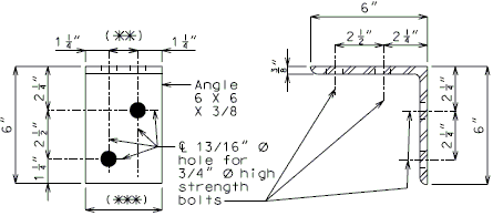
| |
| Front Elevation | Section Thru Angle |
|---|---|
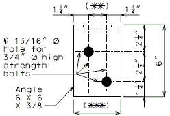
|
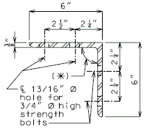
|
| Plan | Section Thru Angle Bridges on Vertical Grade |
| (*) | Angle legs shall be adjusted to conform to the variable angle between bearing stiffener and top flange created by the girder tilt requirement due to vertical grade. |
| (**) | 1/2" for W21 and W24 wide flange beam shapes. 1 1/2" for all other wide flange beams and plate girders. |
| (***) | 3” for W21 and W24 wide flange beam shapes. 4” for all other wide flange beams and plate girders. |
| Stiffener Thickness (in) | |||||||||||||||||||
|---|---|---|---|---|---|---|---|---|---|---|---|---|---|---|---|---|---|---|---|
| Skew | 1/2 | 5/8 | 3/4 | 7/8 | 1 | 1 1/8 | 1 1/4 | 1 3/8 | 1 1/2 | 1 5/8 | 1 3/4 | 1 7/8 | 2 | 2 1/8 | 2 1/4 | 2 3/8 | 2 1/2 | 2 5/8 | |
| 0° THRU 5° | A | A | A | A | A | A | A | A | A | A | A | A | A | A | B | B | B | B | |
| 6° THRU 10° | A | A | A | A | A | B | B | B | B | B | B | B | B | B | B | B | B | B | |
| 11° THRU 15° | A | A | B | B | B | B | B | B | B | B | B | B | B | B | B | B | B | B | |
| 16° THRU 20° | A | B | B | B | B | B | B | B | B | B | B | B | B | B | B | B | B | B | |
| 21° THRU 25° | B | B | B | B | B | B | B | B | B | B | B | B | B | B | B | B | B | B | |
| 26° THRU 30° | B | B | B | B | B | B | B | B | B | B | B | B | B | B | B | B | B | B | |
| 31° THRU 35° | C | C | C | C | C | C | C | C | C | C | C | C | C | C | C | C | C | C | |
| 36° THRU 40° | C | C | C | C | C | C | C | C | C | C | C | C | C | C | C | C | C | C | |
| 41° THRU 45° | C | C | C | C | C | C | C | C | C | C | C | C | C | C | C | C | C | C | |
751.14.5.2 Int. Diaphragms and Cross Frames
Refer to EPG 751.14.5.10 for weld design and detail guidance. Refer to EPG 751.14.5.5 Transverse Stiffeners for beveled plate guidance for unequal flange widths.
The preferred welded connection to flange is more prone to fatigue than the bolted connection. Girder shall be sized to reduce fatigue stresses to allow for preferred detail. If resizing is impractical, the bolted connection shall be used. When the bolted connection is used, the top and bottom tension or compression flanges shall be shown on the "Elevation of Girder" detail on plans.
Minimum connection plate size is 5 1/2" x 1/2”. Width of plate shall be increased as required by 1/2" increments. Thickness of plate shall be increased as required by 1/8" increments.
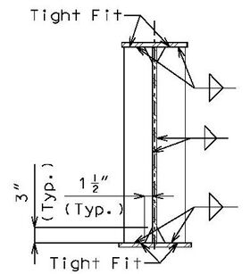
(Preferred detail)
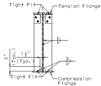
(Optional detail1)
1 Holes in the tension flange restricts girder design in accordance with EPG 751.14.2.2 Analysis Methods
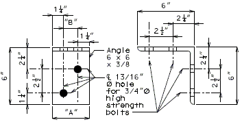
|
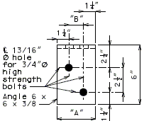
| |
| Front Elevation Detail of Flange Connection Angle |
Section thru Flange Connection Angle 6 x 6 x 3/8 |
Plan Detail of Flange Connection Angle |
|---|---|---|
Diaphragm Details
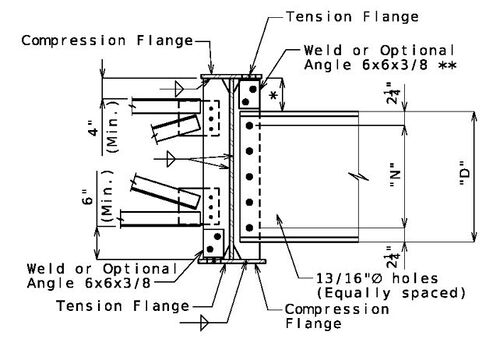
| ||||
| ||||
| See table below for "D" and "N" values. | ||||
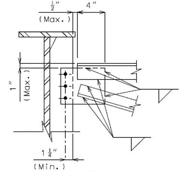
| ||||
| Diaphragm Connection at Stiffener Detail |
|---|
| Note: | The above details are assumed adequate for straight girders. Horizontally curved girders require design for torsional effects (see Analysis of Horizontally Curved Girders). |
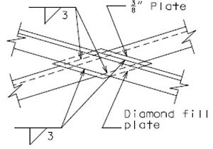
|
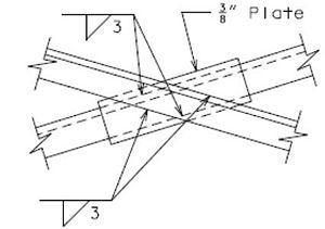
|
| Fill Plate Detail - Preferred | Optional Fill Plate Detail for Contractor |
|---|
Refer to EPG 751.14.5.10 for weld design and detail guidance.
| Shape | "D" (in) | "N" | Channel, Angle or Bent Plate |
"A" (in) | "B" (in) |
|---|---|---|---|---|---|
| W21X48 THRU W21X93 | 12 | 4 | C12 x 20.7 | 3 | 1/2 |
| W24X68 THRU W24X103 | 12 | 4 | C12 x 20.7 | 3 | 1/2 |
| W27X84 THRU W27X129 | 15 | 4 | 5/16 x 23 | 4 | 1 1/2 |
| W30X90 THRU W30X148 | 18 | 5 | 5/16 x 26 | 4 | 1 1/2 |
| W33X118 THRU W33X221 | 21 | 5 | 5/16 x 29 | 4 | 1 1/2 |
| W36X135 THRU W36X194 | 21 | 5 | 5/16 x 29 | 4 | 1 1/2 |
| W40X149 THRU W40X215 | 21 | 5 | 5/16 x 29 | 4 | 1 1/2 |
| 36" thru 40" Plate Girders | 21 | 5 | 5/16 x 29 | 4 | 1 1/2 |
| 42" Plate Girders | 27 | 5 | 5/16 x 35 | 4 | 1 1/2 |
| > 42" Plate Girders | Diagonal Member | L3x3x5/16 | 4 | 1 1/2 | |
| Horizontal Member |
*** S < 10'-2" | L3.5x3.5x5/16 | |||
| other | L4x4x5/16 | ||||
| ** | Table is applicable for diaphragms and cross frames used as bracing members. For criterion used in determining members sizes see the footnotes for the “Bottom Horizontal Members for Web Depths” and “ Diagonal Members for Web Depths > 48” tables for End Diaphragms. |
| *** | S = girder spacing along diaphragm skew |
| Diaphragms and cross frames used as primary members must be checked for torsion effects. (See Analysis of Horizontally Curved Girders) | |
| ATTENTION DETAILER: |
|---|
| Intermediate diaphragm connection plates shall be detailed for Connection “A” for skews thru 20˚. Details of Connection “A” are shown in EPG 751.14.5.1 Bearing Stiffeners. |
751.14.5.3 End Diaphragms for Wide Flange Beams
| W21 thru W30 | Beam Spacing, ft. | |||||||
|---|---|---|---|---|---|---|---|---|
| Skew, deg. | 7 | 7.5 | 8 | 8.5 | 9 | 9.5 | 10 | 10.5 |
| 0 | C15x33.9 | C15x33.9 | C15x40 | C15x50 | C15x50 | W16x36 | W16x40 | W16x40 |
| 10 | C15x33.9 | C15x40 | C15x40 | C15x50 | C15x50 | W16x36 | W16x40 | W16x40 |
| 20 | C15x33.9 | C15x40 | C15x50 | C15x50 | W16x36 | W16x40 | W16x40 | W16x45 |
| 30 | C15x40 | C15x50 | C15x50 | W16x36 | W16x40 | W16x40 | W16x45 | W16x45 |
| 40 | C15x50 | W16x36 | W16x40 | W16x45 | W16x45 | W16x50 | W16x50 | W16x57 |
| 50 | W16x40 | W16x45 | W16x50 | W16x50 | W16x57 | W16x57 | W16x67 | W16x67 |
| 60 | W16x57 | W16x67 | W16x67 | W16x67 | W16x67 | W16x77 | W16x77 | W16x89 |
| W33 | Beam Spacing, ft. | |||||||
|---|---|---|---|---|---|---|---|---|
| Skew, deg. | 7 | 7.5 | 8 | 8.5 | 9 | 9.5 | 10 | 10.5 |
| 0 | W16x31 | W16x31 | W16x31 | W16x36 | W16x36 | W16x36 | W16x40 | W16x40 |
| 10 | W16x31 | W16x31 | W16x31 | W16x36 | W16x36 | W16x36 | W16x40 | W16x40 |
| 20 | W16x31 | W16x31 | W16x36 | W16x36 | W16x36 | W16x40 | W16x40 | W16x45 |
| 30 | W16x31 | W16x36 | W16x36 | W16x36 | W16x40 | W16x40 | W16x45 | W16x45 |
| 40 | W16x36 | W16x36 | W16x40 | W16x45 | W16x45 | W16x50 | W16x50 | W16x57 |
| 50 | W16x40 | W16x45 | W16x50 | W16x50 | W16x57 | W16x57 | W16x67 | W16x67 |
| 60 | W16x57 | W16x67 | W16x67 | W16x67 | W16x67 | W16x77 | W16x77 | W16x89 |
| W36 | Beam Spacing, ft. | |||||||
|---|---|---|---|---|---|---|---|---|
| Skew, deg. | 7 | 7.5 | 8 | 8.5 | 9 | 9.5 | 10 | 10.5 |
| 0 | W18x35 | W18x35 | W18x35 | W18x35 | W18x35 | W18x35 | W18x40 | W18x40 |
| 10 | W18x35 | W18x35 | W18x35 | W18x35 | W18x35 | W18x35 | W18x40 | W18x40 |
| 20 | W18x35 | W18x35 | W18x35 | W18x35 | W18x35 | W18x40 | W18x40 | W18x40 |
| 30 | W18x35 | W18x35 | W18x35 | W18x35 | W18x40 | W18x40 | W18x46 | W18x46 |
| 40 | W18x35 | W18x35 | W18x40 | W18x40 | W18x46 | W18x46 | W18x50 | W18x50 |
| 50 | W18x40 | W18x46 | W18x46 | W18x50 | W18x50 | W18x55 | W18x55 | W18x60 |
| 60 | W18x50 | W18x55 | W18x60 | W18x65 | W18x65 | W18x71 | W18x76 | W18x76 |
| W40 thru W44 | Beam Spacing, ft. | |||||||
|---|---|---|---|---|---|---|---|---|
| Skew, deg. | 7 | 7.5 | 8 | 8.5 | 9 | 9.5 | 10 | 10.5 |
| 0 | W21x44 | W21x44 | W21x44 | W21x44 | W21x44 | W21x44 | W21x44 | W21x44 |
| 10 | W21x44 | W21x44 | W21x44 | W21x44 | W21x44 | W21x44 | W21x44 | W21x44 |
| 20 | W21x44 | W21x44 | W21x44 | W21x44 | W21x44 | W21x44 | W21x44 | W21x44 |
| 30 | W21x44 | W21x44 | W21x44 | W21x44 | W21x44 | W21x44 | W21x44 | W21x44 |
| 40 | W21x44 | W21x44 | W21x44 | W21x44 | W21x44 | W21x44 | W21x44 | W21x48 |
| 50 | W21x44 | W21x44 | W21x44 | W21x44 | W21x48 | W21x48 | W21x55 | W21x55 |
| 60 | W21x48 | W21x50 | W21x55 | W21x55 | W21x62 | W21x62 | W21x68 | W21x73 |
| Note: | The values in the table above may be used for both straight and horizontally curved beams. |
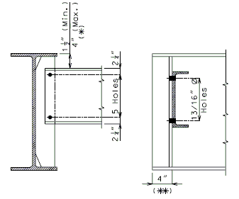
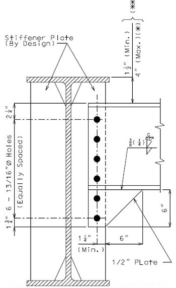
Refer to EPG 751.14.5.10 for weld design and detail guidance.
| (*) | Slope diaphragms when structure is superelevated or when 4” maximum depth is exceeded. See EPG 751.13 Expansion Devices for the details of end diaphragms on a structure. |
| (**) | Modify if necessary to clear the anchor bolts of the flat plate bearing or connection bolts of the expansion device. |
All Sizes
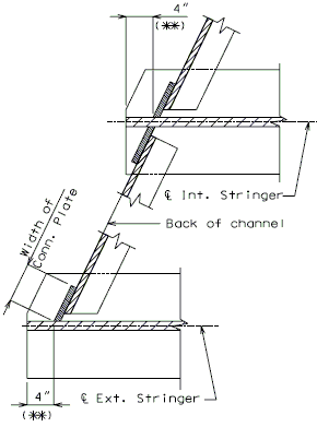
| ATTENTION DETAILER: |
|---|
| End diaphragms shall be detailed horizontally, stepped, or sloped as required. |
751.14.5.4 End Diaphragms for Plate Girders
| Webs Thru 40" | Girder Spacing, ft. | |||||||
|---|---|---|---|---|---|---|---|---|
| Skew, deg. | 7 | 7.5 | 8 | 8.5 | 9 | 9.5 | 10 | 10.5 |
| 0 | W21x44 | W21x44 | W21x44 | W21x44 | W21x44 | W21x44 | W21x44 | W21x44 |
| 10 | W21x44 | W21x44 | W21x44 | W21x44 | W21x44 | W21x44 | W21x44 | W21x44 |
| 20 | W21x44 | W21x44 | W21x44 | W21x44 | W21x44 | W21x44 | W21x44 | W21x44 |
| 30 | W21x44 | W21x44 | W21x44 | W21x44 | W21x44 | W21x44 | W21x44 | W21x44 |
| 40 | W21x44 | W21x44 | W21x44 | W21x44 | W21x44 | W21x44 | W21x44 | W21x48 |
| 50 | W21x44 | W21x44 | W21x44 | W21x44 | W21x48 | W21x48 | W21x55 | W21x55 |
| 60 | W21x48 | W21x50 | W21x55 | W21x55 | W21x62 | W21x62 | W21x68 | W21x73 |
| Webs ≥ 42" | Girder Spacing, ft. | |||||||
|---|---|---|---|---|---|---|---|---|
| Skew, deg. | 7 | 7.5 | 8 | 8.5 | 9 | 9.5 | 10 | 10.5 |
| 0 | C15x33.9 | C15x33.9 | C15x40 | C15x50 | C15x50 | W16x36 | W16x40 | W16x40 |
| 10 | C15x33.9 | C15x40 | C15x40 | C15x50 | C15x50 | W16x36 | W16x40 | W16x40 |
| 20 | C15x33.9 | C15x40 | C15x50 | C15x50 | W16x36 | W16x40 | W16x40 | W16x45 |
| 30 | C15x40 | C15x50 | C15x50 | W16x36 | W16x40 | W16x40 | W16x45 | W16x45 |
| 40 | C15x50 | W16x36 | W16x40 | W16x45 | W16x45 | W16x50 | W16x50 | W16x57 |
| 50 | W16x40 | W16x45 | W16x50 | W16x50 | W16x57 | W16x57 | W16x67 | W16x67 |
| 60 | W16x57 | W16x67 | W16x67 | W16x67 | W16x67 | W16x77 | W16x77 | W16x89 |
| Webs ≥ 42" | Girder Spacing, ft. | |||||||
|---|---|---|---|---|---|---|---|---|
| Skew, deg. | 7 | 7.5 | 8 | 8.5 | 9 | 9.5 | 10 | 10.5 |
| 0 thru 10 | L3 1/2x3 1/2x5/16 | L3 1/2x3 1/2x5/16 | L3 1/2x3 1/2x5/16 | L3 1/2x3 1/2x5/16 | L4x4x5/16 | L4x4x5/16 | L4x4x5/16 | L4x4x5/16 |
| 20 | L3 1/2x3 1/2x5/16 | L3 1/2x3 1/2x5/16 | L3 1/2x3 1/2x5/16 | L3 1/2x3 1/2x5/16 | L4x4x5/16 | L4x4x5/16 | L4x4x5/16 | L4x4x5/16 |
| 30 | L3 1/2x3 1/2x5/16 | L3 1/2x3 1/2x5/16 | L4x4x5/16 | L4x4x5/16 | L4x4x5/16 | L4x4x5/16 | L4x4x5/16 | L5x5x5/16 |
| 40 | L3 1/2x3 1/2x5/16 | L4x4x5/16 | L4x4x5/16 | L4x4x5/16 | L5x5x5/16 | L5x5x5/16 | L5x5x5/16 | L5x5x5/16 |
| 50 | L4x4x5/16 | L4x4x5/16 | L5x5x5/16 | L5x5x5/16 | L5x5x5/16 | L5x5x5/16 | L6x6x3/8 | L6x6x3/8 |
| 60 | L5x5x5/16 | L5x5x5/16 | L6x6x3/8 | L6x6x3/8 | L6x6x3/8 | L6x6x3/8 | WT6x17.5 | WT6x17.5 |
| Webs ≤ 60" | Girder Spacing, ft. | |||||||
|---|---|---|---|---|---|---|---|---|
| Skew, deg. | 7 | 7.5 | 8 | 8.5 | 9 | 9.5 | 10 | 10.5 |
| 0 thru 50 | L3x3x5/16 | L3x3x5/16 | L3x3x5/16 | L3x3x5/16 | L3x3x5/16 | L3x3x5/16 | L3x3x5/16 | L3x3x5/16 |
| 60 | L3x3x5/16 | L3x3x5/16 | L3x3x5/16 | L3x3x5/16 | L3 1/2x3 1/2x5/16 | L3 1/2x3 1/2x5/16 | L3 1/2x3 1/2x5/16 | L3 1/2x3 1/2x5/16 |
| Webs < 112" | Girder Spacing, ft. | |||||||
|---|---|---|---|---|---|---|---|---|
| Skew, deg. | 7 | 7.5 | 8 | 8.5 | 9 | 9.5 | 10 | 10.5 |
| 40 | L3x3x5/16 | L3x3x5/16 | L3x3x5/16 | L3x3x5/16 | L3x3x5/16 | L3x3x5/16 | L3x3x5/16 | L3x3x5/16 |
| 60 | L3x3x5/16 | L3x3x5/16 | L3 1/2x3 1/2x5/16 | L3 1/2x3 1/2x5/16 | L3 1/2x3 1/2x5/16 | L3 1/2x3 1/2x5/16 | L3 1/2x3 1/2x5/16 | L3 1/2x3 1/2x5/16 |
For girder spacing or skews not listed in table, use nearest tabulated angle size.
Enter the tables with the skew of the diaphragm, not the bridge skew.
The members in Tables 2 and 3 were selected to meet only the slenderness requirement . For diagonal bracing members the following values were used for equal leg single angle members:
L3x3x5/16 = 0.85 L3 1/2x3 1/2x5/16 and longer leg lengths = 0.75
For horizontal bracing members the following K values were used for equal leg single angle members:
L3x3x5/16 = 1.1 L3 1/2x3 1/2x5/16 = 0.95 L4x4x5/16 = 0.85 L5x5x5/16 = 0.80 L6x6x3/8 = 0.75
The above values were determined using the following reference article: “Critical Slenderness of Compression Members with Effective Lengths about Nonprincipal Axes”, L. A. Lutz (1992)
For WT shapes: = 0.75 (in-plane), 1.0 (out-of-plane)
Member lengths, l, were measured from the center of bolted connection. The center of bolted connection is assumed to be located 3.5” perpendicular to CL web. Vertically, diagonal members are assumed to extend to 2 3/8” from outer gusset plate edge. In-plane bending was assumed to be fixed-fixed while out-of-plane bending is assumed to be pinned at the bolted connection and fixed at the diagonal member crossing. Diagonal members are assumed to be braced in the middle.
For diaphragms and cross-frames designed as primary members in horizontally curved girders:
Primary members shall also be designed for torsional effects. (See Analysis of Horizontally Curved Girders)
End Diaphragms

| |
| End Diaphragm - 36" Thru 40" Webs | |
|---|---|
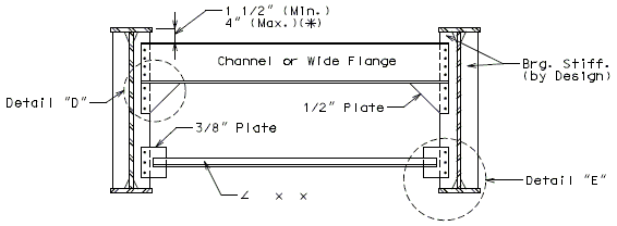
| |
| End Diaphragm - 42" Thru 48" Webs | |
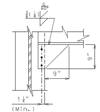
|
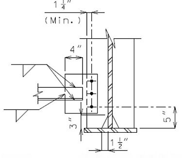
|
| Detail "D" | Detail "E" |
| Haunch slab to bear on channel or wide flange. | |
| (*) | Slope diaphragms when a structure is superelevated or when the 4" maximum depth is exceeded. |
Refer to EPG 751.14.5.10 for weld design and detail guidance.
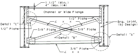
| |
| End Diaphragm - Webs Over 48" | |
|---|---|
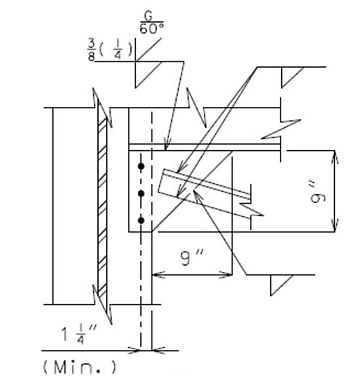
|
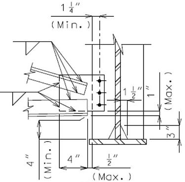
|
| Detail "C" | Detail "A" |
| Haunch slab to bear on channel or wide flange. | |
| (*) | Slope diaphragms when a structure is superelevated or when the 4" maximum depth is exceeded. |
Refer to EPG 751.14.5.10 for weld design and detail guidance.
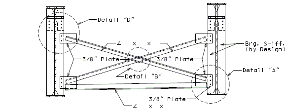
| |
| End Diaphragm - Webs Over 48" Structure with Finger Plate Expansion Device | |
|---|---|
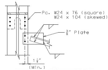
|
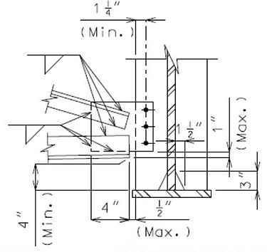
|
| Detail "D" | Detail "A" |
Refer to EPG 751.14.5.10 for weld design and detail guidance.
751.14.5.5 Transverse Stiffeners
Transverse stiffeners are also referred to as intermediate web stiffeners.
Minimum stiffener size is 5 1/2" x 1/2”. Width of plate shall be increased as required by 1/2" increments. Thickness of plate shall be increased as required by 1/8" increments.
Transverse stiffeners shall be used on inside face of exterior girders and in successive alignment along either side of interior girders.
When transverse stiffeners are used, top and bottom tension or compression flanges shall be shown on the "Elevation of Girder" detail on plans.
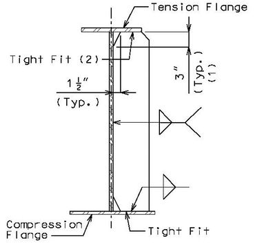
| ||
| Int. web Stiffener (One Side Only) Variable Flange Width |
||
|---|---|---|
| Refer to EPG 751.14.5.10 for weld design and detail guidance. | ||
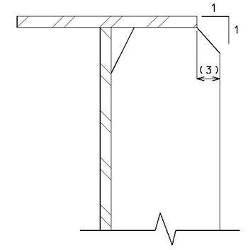
| ||
| Details of Beveled Plate for Int. Web Stiffener, Bearing Stiffener and Intermediate Diaphragm Connection Plates | ||
| (1) | Check LRFD 6.10.11.1.1 for clip limits. |
| (2) | Attach to flange when stiffener is also used as a diaphragm connection plate. |
| (3) | When dimension exceeds 1/2", bevel stiffener plate. |
751.14.5.6 Longitudinal Stiffeners
| When longitudinal stiffeners are required they shall be used on the outside of exterior girders and in successive alignment along either side of interior girders. | 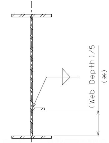
|
| The placement of longitudinal stiffeners may interfere with bolting the diaphragm or cross frame in place. Should this occur, it will be necessary to clip the longitudinal stiffeners as shown below. | |
| Also, when lateral bracing is required, place the longitudinal stiffener on the opposite side of girder. | |
| The appropriate details shown below shall be modified as needed and placed on the design plans. | |
| (*) Location shall satisfy requirements of LRFD 6.10.8.3. | |
| Longitudinal Web Stiffener (One Side Only) Refer to EPG 751.14.5.10 for weld design and detail guidance. |
|---|
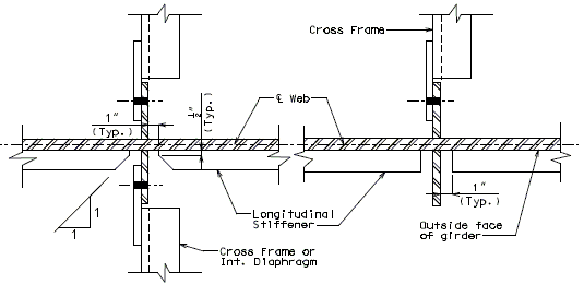
| |
| Interior Girders Square or Skewed |
Exterior Girders at Intermediate Bearing Stiffeners |
|---|---|
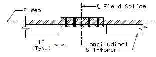
| |
| Typical Section at Bolted Field Splice | |
751.14.5.7 Lateral Bracing
Lateral bracing shall be omitted on all spans ft. Lateral bracing may be omitted on spans ft provided the girder meets all applicable Strength limit states.
Lateral bracing shall be placed in outer bays.
Members selected shall meet requirements of bracing members with .
Under no circumstance shall lateral bracing be detailed to go through diaphragms. In order to facilitate erection, structural tees for lateral bracing may be inverted to connect to the top gusset plates.
Whenever practicable, diaphragms and lateral bracing shall connect to bearing stiffeners in bridges having large skews, diaphragms and lateral bracing need not connect to end bearing stiffeners for such structures but should connect to a girder midway between the bearing stiffener and the first transverse web stiffener.
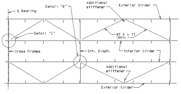
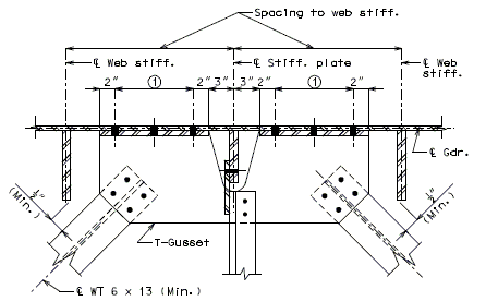
| |
| Spaced at 2" (Min.), 3" (Max.) | |
| Detail "B" | |
|---|---|
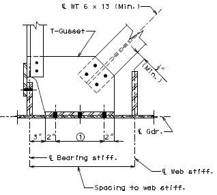
|
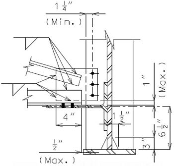
|
| Detail "C" | Detail "A" |
| Note: | Lateral Bracing T-Gusset shall be cut to required depth from W27 x 94, or T-Gusset can be built from plates in shop. |
| Refer to EPG 751.14.5.10 for weld design and detail guidance. |

| |
| (*) | Locate T-Gusset as shown above, dimension at all connections should be constant from top of bottom flange. |
| Place following not on plans: | Note: T-Gusset shall be placed (*) inches above top of bottom flange. |
| Constant Depth Girders | |
|---|---|

| |
| (**) | Locate T-Gusset as shown above, dimension at all connections should be constant from top of bottom flange in constant web depth portions. |
| Constant - Variable Depth Girders | |

| |
| (***) | Locate T-Gusset as shown above, dimension at all connections thru tapered section should be constant from top of bottom flange (Slope T-Gusset same as bottom flange). Continue same slope through variable depth section of girders. |
| Tapered - Variable Depth Girders | |
751.14.5.8 Protective Coating Requirements
Coating requirements for new steel girder bridge shall be in accordance with Sec 1080 and Sec 1081. See EPG 751.1.2.9.2, EPG 751.6.2.11 and EPG 751.6.2.12 for additional guidance.
System G (three-coat system) is the preferred system for both non-weathering and weathering steel structures (Sec 1081). System G typically is not preferred when overlapping an existing vinyl coating but may be allowed if the existing coating is determined to be in good condition. System G uses a solvent based finish coat which may cause issues when overlapping an existing solvent-based vinyl coating system (System C) because it may re-wet the existing coating and cause delamination of the base coat. If the existing coating is in good condition as determined by paint pull-off tests the intermediate epoxy coating will provide a reliable barrier between the solvent-based coatings. Consult the structural project manager or structural liaison engineer before using System G near existing vinyl coatings.
System G has replaced calcium sulfonate as the preferred overcoating system. To ensure sufficient bond of the existing coating, adhesion pull-off tests shall be performed in accordance with ASTM D4541. If the adhesion test fails, as determined by the engineer of record, then overcoating shall not be allowed and recoating should be considered.
System H (three-coat system) is typically used when the bond for System G is considered questionable where recoating operations will take place near an existing vinyl coating system (System C). System H uses a waterborne acrylic for the intermediate and finish field coats that does not tend to interfere with the solvent-based vinyl coating.
System I (two-coat system) may be used for non-weathering and weathering steel and should be based on the following guidance:
- (a) System I should be considered in areas where the aesthetics of a coating system over the long term is unusually more critical than System G. While System G and I provide long term protection, System I has excellent gloss retention and UV resistance. System I is a context sensitive design (CSD) solution. CSD follows from project scoping and is subject to the project core team protocols.
- (1) Consider for locations where the structure is more visible or the public has leisurely time for more than just a casual glance, for example structures near a ballpark or a pedestrian bridge. Using same rationale, bridges that are tall or have wide girder spacing or a low number of girders where more of the superstructure is visible could also be candidates.
- (2) Consider the image consciousness of the surroundings in conjunction with rather than solely the protection of the structure which is equally provided by both systems. Maintenance of either System G or I should be considered the same.
- (b) System I is a polysiloxane finish coat that is normally applied directly over an inorganic or organic zinc primer with no intermediate coating. Since the system is a two-coat system, it may be applied in less time which can influence critical path scheduling and impacts to the driving public. For example, it may be possible for a contractor to get in and out quicker than if they were to use a three-coat system. MoDOT coating policy as described in Standard Specification Section 1081 requires different field coating requirements based on the type of bridge crossing. For roadway grade separations, it is required that interior girders have only a single field coat in order to satisfy that all girders on a roadway grade separation bridge have at least two coatings for protection. In the case of System I, the Standard Specifications require that a System G epoxy intermediate field coat be applied to all interior girders and the interior of fascia girders and that the System I polysiloxane finish coating be applied to the exterior of the facia girders only. This is based on a system I polysiloxane coating cost being greater than a system G epoxy coating on a per-gallon cost basis. It also requires that the contractor be given the option to substitute the System I finish coat in place of a System G intermediate coat. If CSD determines that the polysiloxane should be applied to all girders, then the general notes for coatings and the quantities on the contract plans will need to reflect the revised coating requirements.
- (c) System I is approved for use on state highway projects beginning February 2011. Alternate bidding is encouraged if guideline (a) is not required to be met and with approval of the Structural Project Manager or Structural Liaison Engineer and the project core team.
System G, H or I typically require an inorganic or organic zinc primer per Sec 1081. Inorganic zinc shall be used for new steel fabrication. For recoating operations, organic zinc primer should be considered as a direct replacement for the inorganic zinc required in the specifications. Organic zinc primers require a lower level of surface preparation (SSPC-SP6: commercial blast cleaning vs SSPC-SP10: near white blast cleaning) and are generally easier to apply in the field than inorganic zinc primers. Only organic zinc primers that can provide a Class B slip coefficient are allowed for use in recoating operations.
See EPG 751.50 A4. Protective Coatings for standard detailing notes and guidance on how they are used.
Epoxy-mastic primers may be used for overcoating lead-based coatings if the existing coating is determined to be in good condition, but this is considered a short-term solution in comparison to System G overcoating. Consult the structural project manager or structural liaison engineer before using epoxy-mastics near existing lead-based coatings.
Galvanized non-weathering structural steel beams, girders, bracing and diaphragms may be used as required or allowed by alternate, on a case-by-case basis, with approval of the Structural Project Manager or Structural Liaison Engineer and the project core team.
When galvanized structural steel is required, place note EPG 751.50 (A4a1.8.2a) on the plans. Do not use notes EPG 751.50 (A4a1.1 – A4a1.7). When galvanized structural steel is bid as an alternate, place notes EPG 751.50 (A4a1.8.1a, A4a1.8.1b, and A4a1.8.1c) on the plans under the applicable coating new steel notes EPG 751.50 (A4a1.1-A4a1.7).
751.14.5.9 Weathering Steel
Use of weathering steel may require special detailing as specified in the referenced documents in EPG 751.1.2.9 Girder Type Selection.
751.14.5.9.1 Drip Bar Guidance
General
The purpose of a drip bar placed on the bottom flange is to intercept and deflect water and debris. Drip bars should be installed on new, or retrofitting existing weathering steel where a need is discovered.
Drip bars should be utilized for three reasons:
1. To protect girders and beams from sustained and accumulated (heavy) water flow along the web-flange crease that can promote deterioration by wearing action (due to particulate matter and debris) and long term moisture retention along the crease and along the lower web whereby water is drawn up the sides of the lower web by capillary action which is observable in the field as constantly "wetted" sides or permanent discoloration. For a new girder or beam, this can retard the development of or reduce the efficacy of the protective oxide coating.
2. To protect bearing devices from sustained moisture due to accumulating water and debris.
3. To protect substructure from long term staining. (For the short term, temporary protective coating is utilized during weathering steel construction; see EPG 711 Protective Coatings for Exposed Concrete Surfaces.)
Guidance
Drip bars shall not be provided on flat structures (0.0 % grade) unless in the case of long spans where permanently cambered girders or beams can produce a water flow.
Drip bars shall be placed skewed on top of bottom flange and preferably placed squared on bottom of bottom flange.
Drip bars shall not be provided directly over railroads, roadways and walkways.
(Case 1) To protect girders and beams: Drip bars should be located at the downgrade side of open or closed expansion devices between 5 ft. from the center of the expansion device and to within 1 ft. from the end of the partial coating limit (to ensure the drip bars are coated) for all girders or beams within a span.
(Case 2) To protect girder and beam ends, bearings and bearing stiffeners: Drip bars should be located at the upgrade side of bearings at the exterior faces of exterior girders or beams at about 4 ft. away from the face of the bent for downhill runs of 100 ft. or longer span girders or beams.
(Case 3) To protect substructure: Drip bars should be located adjacent to the upgrade side of the bent at the exterior faces of exterior girders or beams at about 4 ft. away from the face of the bent for downhill runs of 100 ft. or longer span girders or beams to prevent stain marks on the substructure in either urban or context sensitive designs, for example where the aesthetics of the structure is considered important. For aesthetics reasons drip bars adjacent to substructure may be provided where the structure is over railroad, water or near integral abutments.
Fatigue analysis of girder or beam for welded connection of drip bars shall be required in the event that there will be effective stress cycles in tension and/or stress reversal on the welds. Bolted drip angle details may be considered instead of welded drip bars details as an alternative.
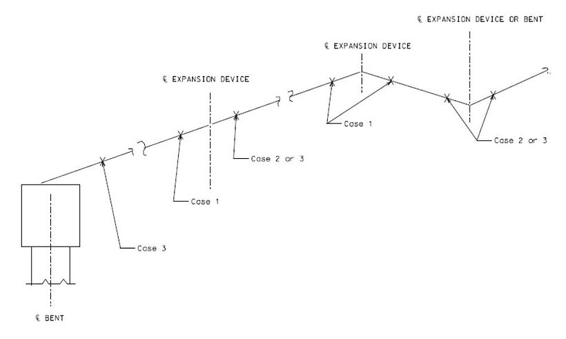
| Notes: |
| Identify direction of grade on plans and orient drip bar accordingly to deflect water and debris. |
| Case 1 - Provide drip bar detail at all girders to block water from expansion device to protect the girders. |
| Case 2 or 3 - Provide drip bar detail at exterior face of exterior girders to deflect water and debris from 100 ft. or longer span draining to a bent. |
751.14.5.9.2 Drip Bar Details
| Bridge Standard Drawings – Drip Bar |
|---|
| Drip Bar for Weathered Steel |
Welded drip bar details are preferred because they are simpler, require less work and produce less damage to new or existing weathering steel flanges. Bolted drip angles are optional and should only be used when welded drip bars cannot be used. Both sets of details are not intended to be used as alternates on a single job.
751.14.5.10 Weld Design and Detail Guidance
General
Fillet Welds
Weld design and detail guidance is provided to ensure that the correct fillet weld size is used for fabrication and to reduce incidences of inconsistent and/or incorrect fillet weld sizes shown on the plans which can cause problems for both designer and fabricator.
Preferred MoDOT standard practice is to exclude (leave blank) fillet weld sizes from the bridge plans which is to mean that the fillet weld size shall be determined by the fabricator and that they are contractually obligated to use the minimum fillet weld sizes given in Sec 1080 (shown as the minimum size of fillet weld) of the Standard Specifications.
Excluding fillet weld sizes from the bridge plans is correct in most situations, for example routine welded connections. This accepted and preferred practice prevents the designer from performing unnecessary and complicated load estimates and weld strength computations for mundane welded connections while ensuring consistent plan details for ease of fabrication. Standard Drawings and the details shown in EPG 751.14.5 Details show fillet weld symbols without the fillet weld size and should be assumed adequate for typical applications. Minimum fillet weld sizes are based only on material thickness of parts to be adjoined and are not specific to loading condition or magnitude of load, and are proven empirically to work in practice for typical applications. For more information, see itemized guidance following.
However, excluding fillet weld sizes shall not preclude sound engineering practice of ensuring that a minimum fillet weld size given in accordance with Sec 1080 is acceptable to resist maximum factored loads. This is for typical applications only – ALWAYS CHECK to be sure.
Specialty Welds
For purposes of this section only, any weld not a fillet weld is considered a specialty weld and weld symbol should include all pertinent design information and instruction for fabricating weld, i.e. type, size and instructions.
Itemized Guidance
Itemized guidance is provided to be used for all types of welds.
| No. 1 | Weld design shall be in accordance with AISC Steel Construction Manual, 13th Ed., Part 8; AASHTO LRFD Bridge Design Specifications, Bridge Welding Code AASHTO/AWS D1.5M/D1.5 Bridge Welding Code, Missouri Standard Specifications Sec 1080 and EPG 751.5.9 Miscellaneous Details. |
| No. 2 | The minimum fillet weld size for welding connections shall not be less than the size required by design to resist the maximum factored loads in accordance with LRFD 6.13.3 nor the minimum fillet weld size shown in Sec 1080. |
| No. 3 | Design of welds shall include fatigue investigation and diaphragm moment effects due to bridge skew and curvature effects if applicable. For routine* plate girders and wide flange beams, leave the weld size blank for the stiffener to web weld and use the requirements in the Standard Specifications. For curved plate girders, skews greater than 50° and spans longer than 200 ft., the stiffener to web fillet weld size should be investigated. |
| * Judgment and experience are required to determine this; guidance is provided and may not be strict enough in characterizing nonroutine (or nontypical) bridges. | |
| No. 4 | Fillet weld size for weld connections shall not be shown on the plans if minimum required fillet weld size by design is less than or equal to fillet weld size shown in Sec 1080. (Fabricators and inspectors will use the minimum fillet weld size given in Sec 1080 unless larger fillet weld size is shown on the bridge plans.) |
| No. 5 | Seismic design effects shall also be considered for design of welds when required. |
| No. 6 | Fillet weld size shall be shown on the bridge plans for specialty weld connections, for example, as shown in EPG 751.14.5.3 End Diaphragm Connection for W27 thru W40 beams and EPG 751.14.5.4 End Diaphragm for Plate Girders, Detail “D”. Specialty welds as shown shall be checked for conditions given in No. 4. |
| No. 7 | Working clearance requirements to allow adequate room for welder to make proper welds shall be checked in accordance with AISC Steel Construction Manual, 13th Ed., Part 8; AASHTO Bridge Design LRFD Specifications and Bridge Welding Code AASHTO/AWS D1.5M/D1.5 Bridge Welding Code. |
| No. 8 | Field weld symbols should be shown with fillet weld size. In general, field welding symbols should be shown complete, i.e. include all pertinent design information and instruction for fabricating weld, i.e. type, size and instructions. |
| No. 9 | Angle size for steel diaphragms should be shown without inch (“) marks on the plans. |
| Examples of Design and Detail of Bearing Stiffener Fillet Welds | |
| Ex. 1 Routine Bridge – Nonseismic | |
| Check No. 3 | Routine by criteria (given); no weld size check necessary. |
| Check No. 4 | Leave weld size blank but show weld symbol. |
| Check No. 7 | Check working clearances. Is there adequate clearance to make the weld? |
| Ex. 2 Nonroutine Bridge – Nonseismic | |
| Check No. 3 | Nonroutine by criteria (given); weld size check necessary using No. 1 and No.2; if design fillet weld size <= minimum fillet weld size shown in Sec 1080, do not show fillet weld size (leave blank) on plans, but do show fillet weld symbol. |
| Check No. 4 | Insert design fillet weld size if design fillet weld size > minimum fillet weld size shown in Sec 1080. |
| Check No. 7 | Check working clearances. Is there adequate clearance to make the weld? |
| Ex. 3 Nonroutine Bridge – Seismic | |
| Check No.4 | Nonroutine by criteria (given); weld size check necessary using No. 1 and No. 2. Seismic; Consult with Structural Project Manager or Structural Liaison Engineer to consider developing loads and designing fillet weld size; If design fillet weld size < minimum fillet weld size shown in Sec 1080, do not show fillet weld size (leave blank) on plans, but do show fillet weld symbol. |
| Check No. 5 | Insert design fillet weld size if design fillet weld size > minimum fillet weld size shown in Sec 1080. |
| Check No. 7 | Check working clearances. Is there adequate clearance to make the weld? |
751.14.6 Miscellaneous Details
751.14.6.1 Girder Haunch
| Prestressed Panel Section: | |
|---|---|
| Steel girders shall be cambered when using P/S Panels. | |
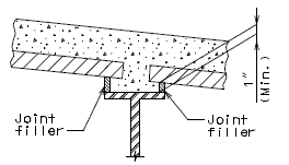
| |
| Cast-in-Place Section: | |
| Cambering steel girders is preferred over varying the haunch profile. For wide flange beams with nominal depths ≥ 36 in., the cambering method required by the fabricator may not be economical and should be compared to the cost of using variable haunching. When variable haunching is used in lieu of cambering, the maximum haunch limit may be maintained by changing girder slopes at field splices. | |
| Slab Haunch Limits: | |
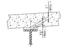
|
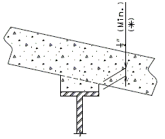
|
| Normal Crown Roadway Slab |
Superelevated Slab |
| (*) | 1/2 in. minimum edge clearance except over splice plates use 1/4 in. min. |
751.14.6.2 Girder Camber and Dead Load Deflection
| Straight Grade (Dead Load Deflection) | ||
|---|---|---|
| Compute Dead load Deflection at 1/4 points for bridges with spans less than 75', at 1/10 points for spans 75' and over. | ||
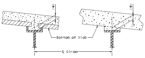
| ||
| Theoretical Slab Haunch |
Theoretical Slab Haunch | |
| (P/C P/S Panel Section) | (C.I.P. Section) | |
| (*) | Dimension (bottom of slab to top of web) may vary if girder camber after erection differs from plan camber by more than the % of Dead Load Deflection due to weight of structural steel. No payment will be made for any adjustment in forming or additional concrete required for variation in haunching. | |
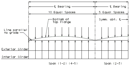
| ||
| Plate Girder Camber Diagram | ||
| Note: | Camber included allowance for _______________. (**) | |
| ___% of dead load deflection due to weight of structural steel. | ||
| (**) | Provide proper notes. | |
| Vertical Curves(Dead Load Deflection) | |||||
|---|---|---|---|---|---|
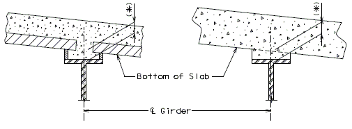
| |||||
| Theoretical Slab Haunch |
Theoretical Slab Haunch | ||||
| (P/C P/S Panel Section) | (C.I.P. Section) | ||||
| (*) | Dimension (bottom of slab to top of web) may vary if girder camber after erection differs from plan camber by more than the % of Dead Load Deflection due to weight of structural steel. No payment will be made for any adjustment in forming or additional concrete required for variation in haunching. | ||||
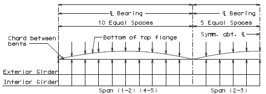
| |||||
| Plate Girder Camber Diagram | |||||
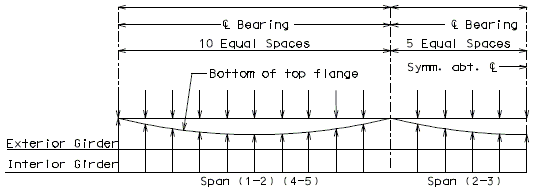
| |||||
| Plate Girder Deflection Diagram | |||||
| Note: | Camber included allowance for _______________. (**) | ||||
| ___% of dead load deflection due to weight of structural steel. | |||||
| (**) | Provide proper notes. | ||||
751.14.6.3 Girder Elevation Variation Sketch
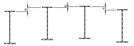

Dimensions showing girder variations shall be placed on the cross section thru slab or, if necessary because of the number and type of variations, the above type of detail and table shall be placed near the structural steel layout.
751.14.6.4 Spacing of Intermediate Diaphragm from Splice
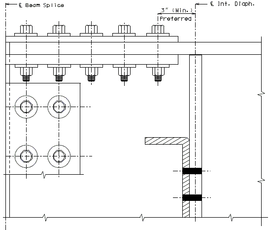
751.14.6.5 Offsets for Curved Plate Girders
Plans for structures having horizontally curved plate girders shall have the detail shown below placed near the plan of structural steel.
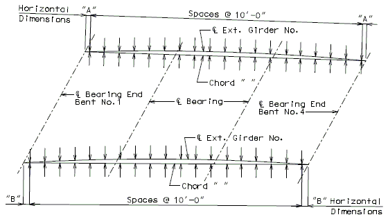
Centerline Girder Curve Offsets
| Note: | Typical example for 3 span structure shown. |


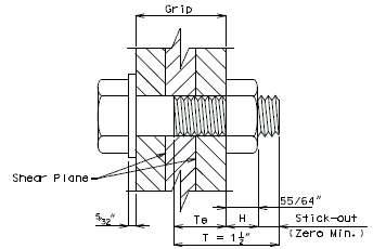


![{\displaystyle \,F_{fat}=MAX{\Bigg [}{\frac {A_{bot}\sigma _{flg}l}{wR}},{\frac {F_{rc}}{w}}{\Bigg ]}}](https://wikimedia.org/api/rest_v1/media/math/render/svg/68d9aaec7576dd908efa155ca8f4993aa5b04668)


