Difference between revisions of "616.12 Work Zone Speed Limits"
m (→616.29.3 Work Zone SPEED LIMIT Figures: Per Traffic, guidance clarification) |
|||
| Line 48: | Line 48: | ||
{|style="border:4px solid #ff9933; background:#f5f5f5" align="right" | {|style="border:4px solid #ff9933; background:#f5f5f5" align="right" | ||
|- | |- | ||
| − | |[[media:616. | + | |[[media:616.29.3.1.pdf|pdf. version of Fig. 616.29.3.1]] |
|- | |- | ||
|} | |} | ||
| Line 57: | Line 57: | ||
! style="background:#BEBEBE" rowspan="2" | Speed!! style="background:#BEBEBE" colspan="2"|Sign Spacing (ft.) !! style="background:#BEBEBE" colspan="2"| Taper Length (ft.)!!style="background:#BEBEBE" rowspan="2"|Optional Buffer Length, B (ft.)!! style="background:#BEBEBE" colspan="2"|Channelizer Spacing (ft.) | ! style="background:#BEBEBE" rowspan="2" | Speed!! style="background:#BEBEBE" colspan="2"|Sign Spacing (ft.) !! style="background:#BEBEBE" colspan="2"| Taper Length (ft.)!!style="background:#BEBEBE" rowspan="2"|Optional Buffer Length, B (ft.)!! style="background:#BEBEBE" colspan="2"|Channelizer Spacing (ft.) | ||
|- | |- | ||
| − | ! style="background:#BEBEBE" |Undivided, S!! style="background:#BEBEBE"|Divided, S!! style="background:#BEBEBE"|Shoulder, T1 | + | ! style="background:#BEBEBE" |Undivided, S!! style="background:#BEBEBE"|Divided, S!! style="background:#BEBEBE"|Shoulder, T1 !! style="background:#BEBEBE"|Lane, T2 !! style="background:#BEBEBE"| Tapers!! style="background:#BEBEBE"|Buffer/Work Areas |
|- | |- | ||
| − | |0 - 35 || 200 || 200 || | + | |0 - 35 || 200 || 200 || colspan="5" rowspan="7" style="background:#ffffcc"|This typical application provides guidelines for the sequencing and location of work zone speed limit signs. Review appropriate typical applications for signs, sign spacing, taper length, buffer length, channelizer spacing, TMAs, channelizers, etc. |
|- | |- | ||
| − | |40 | + | |40 || 350 || 500 |
|- | |- | ||
| − | | | + | |45||350||500 |
|- | |- | ||
| − | |rowspan="3"|60 - 70 ||colspan="2"| SA: 1000 | + | |50 - 55 || 500 || 1000 |
| + | |- | ||
| + | |rowspan="3"|60 - 70 ||colspan="2"| SA: 1000 | ||
|- | |- | ||
|colspan="2"|SB: 1500 | |colspan="2"|SB: 1500 | ||
|- | |- | ||
|colspan="2"|SC: 2640 | |colspan="2"|SC: 2640 | ||
| − | |||
| − | |||
| − | |||
| − | |||
|} | |} | ||
| − | [[image:616. | + | [[image:616.29.3.1.jpg|right|580px]] |
| Line 91: | Line 89: | ||
throughout the entire work zone, per example, head-to-head on multilane applications. | throughout the entire work zone, per example, head-to-head on multilane applications. | ||
| − | ( | + | (1) WO3-5 (SPEED LIMIT XX AHEAD). This sign is used when the approved speed reduction for an immediate location is greater than 10 mph below the existing or posted speed limit. |
| − | ( | + | (2) The SPEED LIMIT sign may be moved upstream, if the district deems the work zone requires |
advance speed limit notification. | advance speed limit notification. | ||
| Line 138: | Line 136: | ||
{|style="border:4px solid #ff9933; background:#f5f5f5" align="right" | {|style="border:4px solid #ff9933; background:#f5f5f5" align="right" | ||
|- | |- | ||
| − | |[[media:616. | + | |[[media:616.29.3.2.pdf|pdf. version of Fig. 616.29.3.2]] |
|- | |- | ||
|} | |} | ||
| + | |||
===Fig. 616.29.3.2 Work Zone SPEED LIMIT Locations within Activity Area=== | ===Fig. 616.29.3.2 Work Zone SPEED LIMIT Locations within Activity Area=== | ||
====<center>''Table 616.29.3.2''</center>==== | ====<center>''Table 616.29.3.2''</center>==== | ||
| Line 147: | Line 146: | ||
! style="background:#BEBEBE" rowspan="2" | Speed!! style="background:#BEBEBE" colspan="2"|Sign Spacing (ft.) !! style="background:#BEBEBE" colspan="2"| Taper Length (ft.)!!style="background:#BEBEBE" rowspan="2"|Optional Buffer Length, B (ft.)!! style="background:#BEBEBE" colspan="2"|Channelizer Spacing (ft.) | ! style="background:#BEBEBE" rowspan="2" | Speed!! style="background:#BEBEBE" colspan="2"|Sign Spacing (ft.) !! style="background:#BEBEBE" colspan="2"| Taper Length (ft.)!!style="background:#BEBEBE" rowspan="2"|Optional Buffer Length, B (ft.)!! style="background:#BEBEBE" colspan="2"|Channelizer Spacing (ft.) | ||
|- | |- | ||
| − | ! style="background:#BEBEBE" |Undivided, S!! style="background:#BEBEBE"|Divided, S!! style="background:#BEBEBE"|Shoulder, T1 | + | ! style="background:#BEBEBE" |Undivided, S!! style="background:#BEBEBE"|Divided, S!! style="background:#BEBEBE"|Shoulder, T1 !! style="background:#BEBEBE"|Lane, T2 !! style="background:#BEBEBE"| Tapers!! style="background:#BEBEBE"|Buffer/Work Areas |
| + | |- | ||
| + | |0 - 35 || 200 || 200 || colspan="5" rowspan="7" style="background:#ffffcc"|This typical application provides guidelines for the sequencing and location of work zone speed limit signs. Review appropriate typical applications for signs, sign spacing, taper length, buffer length, channelizer spacing, TMAs, channelizers, etc. | ||
|- | |- | ||
| − | | | + | |40 || 350 || 500 |
|- | |- | ||
| − | | | + | |45||350||500 |
|- | |- | ||
| − | |50 - 55 || 500 || 1000 | + | |50 - 55 || 500 || 1000 |
|- | |- | ||
| − | |rowspan="3"|60 - 70 ||colspan="2"| SA: 1000 | + | |rowspan="3"|60 - 70 ||colspan="2"| SA: 1000 |
|- | |- | ||
|colspan="2"|SB: 1500 | |colspan="2"|SB: 1500 | ||
|- | |- | ||
|colspan="2"|SC: 2640 | |colspan="2"|SC: 2640 | ||
| − | |||
| − | |||
| − | |||
| − | |||
|} | |} | ||
| − | [[image:616. | + | [[image:616.29.3.2.jpg|right|580px]] |
| Line 181: | Line 178: | ||
This typical application may be appropriate for work zones with a stationary concern within a long activity area. | This typical application may be appropriate for work zones with a stationary concern within a long activity area. | ||
| − | ( | + | (1) If used, the WO3-5 (SPEED LIMIT XX AHEAD) sign shall be located in the Advance Warning Area. |
This sign is used only when the approved speed reduction for an immediate location is greater than 10 mph below the existing or posted speed limit. For sign placement, refer to [[#Fig. 616.29.3.1 Work Zone SPEED LIMIT Locations within Advance Warning Area| | This sign is used only when the approved speed reduction for an immediate location is greater than 10 mph below the existing or posted speed limit. For sign placement, refer to [[#Fig. 616.29.3.1 Work Zone SPEED LIMIT Locations within Advance Warning Area| | ||
EPG 616.29.3.1 Work Zone SPEED LIMIT Locations Within Advance Warning Area]]. | EPG 616.29.3.1 Work Zone SPEED LIMIT Locations Within Advance Warning Area]]. | ||
| − | ( | + | (2) The SPEED LIMIT signs should be located at the farthest upstream activity with |
human presence. | human presence. | ||
| Line 191: | Line 188: | ||
Reduced speed limit signing shall be removed, covered or turned from traffic when conditions requiring the reduced speed no longer exist. | Reduced speed limit signing shall be removed, covered or turned from traffic when conditions requiring the reduced speed no longer exist. | ||
| + | |||
| + | |||
| + | |||
| + | |||
| + | |||
| + | |||
| Line 209: | Line 212: | ||
{|style="border:4px solid #ff9933; background:#f5f5f5" align="right" | {|style="border:4px solid #ff9933; background:#f5f5f5" align="right" | ||
|- | |- | ||
| − | |[[media:616. | + | |[[media:616.29.3.3.pdf|pdf. version of Fig. 616.29.3.3]] |
|- | |- | ||
|} | |} | ||
| Line 220: | Line 223: | ||
! style="background:#BEBEBE" rowspan="2" | Speed!! style="background:#BEBEBE" colspan="2"|Sign Spacing (ft.) !! style="background:#BEBEBE" colspan="2"| Taper Length (ft.)!!style="background:#BEBEBE" rowspan="2"|Optional Buffer Length, B (ft.)!! style="background:#BEBEBE" colspan="2"|Channelizer Spacing (ft.) | ! style="background:#BEBEBE" rowspan="2" | Speed!! style="background:#BEBEBE" colspan="2"|Sign Spacing (ft.) !! style="background:#BEBEBE" colspan="2"| Taper Length (ft.)!!style="background:#BEBEBE" rowspan="2"|Optional Buffer Length, B (ft.)!! style="background:#BEBEBE" colspan="2"|Channelizer Spacing (ft.) | ||
|- | |- | ||
| − | ! style="background:#BEBEBE" |Undivided, S!! style="background:#BEBEBE"|Divided, S!! style="background:#BEBEBE"|Shoulder, T1 | + | ! style="background:#BEBEBE" |Undivided, S!! style="background:#BEBEBE"|Divided, S!! style="background:#BEBEBE"|Shoulder, T1 !! style="background:#BEBEBE"|Lane, T2 !! style="background:#BEBEBE"| Tapers!! style="background:#BEBEBE"|Buffer/Work Areas |
|- | |- | ||
| − | |0 - 35 || 200 || 200 || | + | |0 - 35 || 200 || 200 || colspan="5" rowspan="7" style="background:#ffffcc"|This typical application provides guidelines for the sequencing and location of work zone speed limit signs. Review appropriate typical applications for signs, sign spacing, taper length, buffer length, channelizer spacing, TMAs, channelizers, etc. |
|- | |- | ||
| − | |40 | + | |40 || 350 || 500 |
|- | |- | ||
| − | | | + | |45||350||500 |
|- | |- | ||
| − | |rowspan="3"|60 - 70 ||colspan="2"| SA: 1000 | + | |50 - 55 || 500 || 1000 |
| + | |- | ||
| + | |rowspan="3"|60 - 70 ||colspan="2"| SA: 1000 | ||
|- | |- | ||
|colspan="2"|SB: 1500 | |colspan="2"|SB: 1500 | ||
|- | |- | ||
|colspan="2"|SC: 2640 | |colspan="2"|SC: 2640 | ||
| − | |||
| − | |||
| − | |||
| − | |||
|} | |} | ||
| − | [[image:616. | + | [[image:616.29.3.3.jpg|right|580px]] |
| Line 256: | Line 257: | ||
throughout the entire work zone, per example, head-to-head on multilane applications. | throughout the entire work zone, per example, head-to-head on multilane applications. | ||
| − | ( | + | (1) WO3-5 (SPEED LIMIT XX AHEAD). This sign is used only when the approved speed reduction for an immediate location is greater than 10 mph below the existing or posted speed limit. |
| − | ( | + | (2) The SPEED LIMIT sign may be moved upstream, if the district deems the work zone requires |
advance speed limit notification. | advance speed limit notification. | ||
| Line 265: | Line 266: | ||
For undivided roadways, provide signs only on the right side of each direction. | For undivided roadways, provide signs only on the right side of each direction. | ||
| + | |||
| + | |||
| + | |||
| Line 297: | Line 301: | ||
{|style="border:4px solid #ff9933; background:#f5f5f5" align="right" | {|style="border:4px solid #ff9933; background:#f5f5f5" align="right" | ||
|- | |- | ||
| − | |[[media:616. | + | |[[media:616.29.3.4.pdf|pdf. version of Fig. 616.29.3.4]] |
|- | |- | ||
|} | |} | ||
| Line 308: | Line 312: | ||
For proper speed limit sign spacing, reference typical applications [[#Fig. 616.29.3.1 Work Zone SPEED LIMIT Locations within Advance Warning Area|EPG 616.29.3.1 Work Zone Speed Limit Locations within Advance Warning Area]] or [[#Fig. 616.29.3.2 Work Zone SPEED LIMIT Locations within Activity Area|EPG 616.29.3.2 Work Zone Speed Limit Locations within Activity Area]]. | For proper speed limit sign spacing, reference typical applications [[#Fig. 616.29.3.1 Work Zone SPEED LIMIT Locations within Advance Warning Area|EPG 616.29.3.1 Work Zone Speed Limit Locations within Advance Warning Area]] or [[#Fig. 616.29.3.2 Work Zone SPEED LIMIT Locations within Activity Area|EPG 616.29.3.2 Work Zone Speed Limit Locations within Activity Area]]. | ||
| + | |||
[[Category:616 Temporary Traffic Control]] | [[Category:616 Temporary Traffic Control]] | ||
Revision as of 11:46, 12 January 2011
MoDOT has the authority to set speed limits on the state highway system. This power extends to establishing speed limits in temporary traffic control zones, where the speed limit may be reduced from the normal speed limit for safety purposes. Work zones shall be designed to the normal posted speed limit.
A reduced speed limit should be carefully considered before it is imposed, as motorists will only reduce their speed if they perceive a need to do so. Any decision to reduce the speed limit based on an arbitrary, "across the board" or other inappropriate rationale may result in non-compliance with the reduced speed limit by motorists and a false sense of security for workers.
Should a reduced speed limit be deemed appropriate, the following table shows the recommended maximum speed reductions that may be imposed in temporary traffic control zones.
Contents
- 1 Table 616.29 Recommended Maximum Speed Reductions
- 2 616.29.1 WORK ZONE FINE Sign (CONST-3A)
- 3 616.29.2 Sign Descriptions and Applications
- 4 616.29.3 Work Zone SPEED LIMIT Figures
- 4.1 Fig. 616.29.3.1 Work Zone SPEED LIMIT Locations within Advance Warning Area
- 4.2 Fig. 616.29.3.2 Work Zone SPEED LIMIT Locations within Activity Area
- 4.3 Fig. 616.29.3.3 Work Zone FINE Sign and SPEED LIMIT Locations within Advance Warning Area
- 4.4 Fig. 616.29.3.4 Work Zone SPEED LIMIT Locations for Reductions Greater than 20 mph and Reduction in Two Locations
Table 616.29 Recommended Maximum Speed Reductions
| Activity (i.e. Workers, Equipment or Material) Location | Recommended Work Zone Speed Reduction (When Applicable) | |
|---|---|---|
| 10 ft. beyond edge of travelway to edge of right of way | No speed reduction | |
| In traffic lane or within 10 ft. of the traffic lane | 10 mph | |
| Head-to-head on multilane | 10 mph | |
| Special circumstances within a temporary traffic control work zone may warrant a lower speed limit than recommend above. All speed limit reductions greater than 10 mph shall be documented, submitted to and approved by the District Work Zone Coordinator. | ||
After selecting a reduced speed limit based upon the table above, the following guidelines will assist in the proper installation and application of that reduced speed limit in the temporary traffic control zone.
- On divided highways, the reduced speed is applicable to the affected direction of travel only.
- Existing SPEED LIMIT signs within the temporary traffic control zone shall be covered or removed.
- SPEED LIMIT signs indicating the normal speed limit should be installed at the end of the reduced area provided no other reduction is imposed within the next one-half mile or no existing SPEED LIMIT sign is located within the next one-half mile.
- Reduced speed limit signing shall be removed, covered or turned from traffic when conditions requiring the reduced speed no longer exist.
- For two-lane roadways, normal SPEED LIMIT signs are typically installed opposite the work zone SPEED LIMIT sign on the opposite approach facing traffic leaving the work zone.
- Reduced SPEED LIMIT signs are not to be installed on side street approaches or ramps for work limited to main line only. Reduced SPEED LIMIT signs may be installed downstream from the ramp or side street to inform drivers of the work zone speed limit. If the work is on the ramp, or affects the ramp, reduced SPEED LIMIT signs are to be used.
- Posted work zone speed limit shall not be below 35 mph, except when local ordinance provides for a lower speed. The lower speed shall be used when applicable.
- Appropriate warning signs with advisory speed plaques should be used to advise of any specialized situations (i.e., temporary bypass, narrow lanes, etc.).
- For approved speed reductions greater than 10 mph, additional notification should be provided through the use of the SPEED LIMIT XX AHEAD sign. Refer to EPG 616.29.3 Work Zone SPEED LIMIT Figures.
- For approved speed reductions greater than 20 mph, the speed limit should be reduced in two stages. Refer to EPG 616.29.3 Work Zone SPEED LIMIT Figures.
616.29.1 WORK ZONE FINE Sign (CONST-3A)
The WORK ZONE FINE sign is specified on projects where all the following criteria are met:
- Duration of the work zone is longer than 4 hours.
- Reduced speed limits are in effect.
- Normal posted speed limit is 60 mph or greater.
- Workers will be present without positive protection (concrete barrier or guardrail).
If a lane closure is used on a roadway with two lanes in the direction of travel, two DO NOT PASS and two PASS WITH CARE signs and two CONST-3X, (SPEEDING/PASSING) plates are to be specified. WORK ZONE plaques are to be specified for all DO NOT PASS and PASS WITH CARE signs being used as part of the work zone signing sequence. If a lane closure is used on a roadway with three or more lanes in the direction of travel, the DO NOT PASS and PASS WITH CARE signs and SPEEDING/PASSING plates are not to be specified.
616.29.2 Sign Descriptions and Applications
Sign descriptions and applications are located in EPG 616.2 Work Zone Signing and Applications.
616.29.3 Work Zone SPEED LIMIT Figures
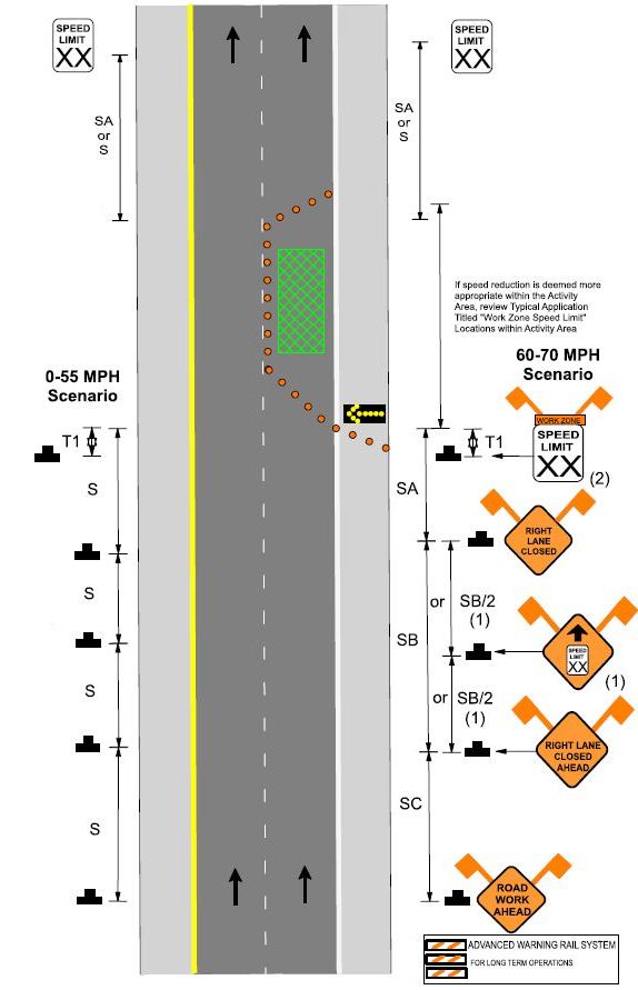
| pdf. version of Fig. 616.29.3.1 |
Fig. 616.29.3.1 Work Zone SPEED LIMIT Locations within Advance Warning Area
Table 616.29.3.1
| Speed | Sign Spacing (ft.) | Taper Length (ft.) | Optional Buffer Length, B (ft.) | Channelizer Spacing (ft.) | |||
|---|---|---|---|---|---|---|---|
| Undivided, S | Divided, S | Shoulder, T1 | Lane, T2 | Tapers | Buffer/Work Areas | ||
| 0 - 35 | 200 | 200 | This typical application provides guidelines for the sequencing and location of work zone speed limit signs. Review appropriate typical applications for signs, sign spacing, taper length, buffer length, channelizer spacing, TMAs, channelizers, etc. | ||||
| 40 | 350 | 500 | |||||
| 45 | 350 | 500 | |||||
| 50 - 55 | 500 | 1000 | |||||
| 60 - 70 | SA: 1000 | ||||||
| SB: 1500 | |||||||
| SC: 2640 | |||||||
For speed limit guidance, refer to EPG 616.29 Work Zone Speed Limits.
This typical application may be appropriate for single location work, per example, bridge work, culvert repair, localized pavement repair.
This typical application may be appropriate for work zone that may require a decrease of speed throughout the entire work zone, per example, head-to-head on multilane applications.
(1) WO3-5 (SPEED LIMIT XX AHEAD). This sign is used when the approved speed reduction for an immediate location is greater than 10 mph below the existing or posted speed limit.
(2) The SPEED LIMIT sign may be moved upstream, if the district deems the work zone requires advance speed limit notification.
For undivided roadways, provide signs only on the right side of each direction.
Reduced speed limit signing shall be removed, covered, or turned from traffic when conditions requiring the reduced speed no longer exist.
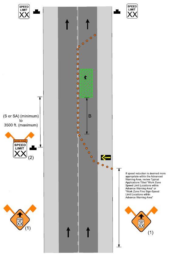
| pdf. version of Fig. 616.29.3.2 |
Fig. 616.29.3.2 Work Zone SPEED LIMIT Locations within Activity Area
Table 616.29.3.2
| Speed | Sign Spacing (ft.) | Taper Length (ft.) | Optional Buffer Length, B (ft.) | Channelizer Spacing (ft.) | |||
|---|---|---|---|---|---|---|---|
| Undivided, S | Divided, S | Shoulder, T1 | Lane, T2 | Tapers | Buffer/Work Areas | ||
| 0 - 35 | 200 | 200 | This typical application provides guidelines for the sequencing and location of work zone speed limit signs. Review appropriate typical applications for signs, sign spacing, taper length, buffer length, channelizer spacing, TMAs, channelizers, etc. | ||||
| 40 | 350 | 500 | |||||
| 45 | 350 | 500 | |||||
| 50 - 55 | 500 | 1000 | |||||
| 60 - 70 | SA: 1000 | ||||||
| SB: 1500 | |||||||
| SC: 2640 | |||||||
For speed limit guidance, refer to EPG 616.29 Work Zone Speed Limits.
This typical application may be appropriate for moving operations when acitivities will move along the travelway, per example, resurfacing projects, pavement repair, concrete overlay, pavement marking, etc.
This typical application may be appropriate for work zones with a stationary concern within a long activity area.
(1) If used, the WO3-5 (SPEED LIMIT XX AHEAD) sign shall be located in the Advance Warning Area. This sign is used only when the approved speed reduction for an immediate location is greater than 10 mph below the existing or posted speed limit. For sign placement, refer to EPG 616.29.3.1 Work Zone SPEED LIMIT Locations Within Advance Warning Area.
(2) The SPEED LIMIT signs should be located at the farthest upstream activity with human presence.
For undivided roadways, provide signs only on the right side of each direction.
Reduced speed limit signing shall be removed, covered or turned from traffic when conditions requiring the reduced speed no longer exist.
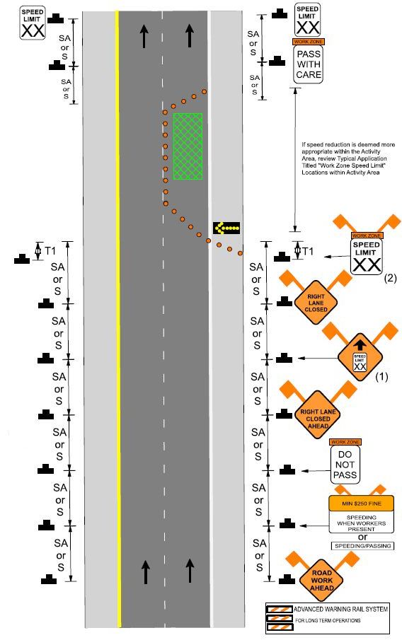
| pdf. version of Fig. 616.29.3.3 |
Fig. 616.29.3.3 Work Zone FINE Sign and SPEED LIMIT Locations within Advance Warning Area
Table 616.29.3.3
| Speed | Sign Spacing (ft.) | Taper Length (ft.) | Optional Buffer Length, B (ft.) | Channelizer Spacing (ft.) | |||
|---|---|---|---|---|---|---|---|
| Undivided, S | Divided, S | Shoulder, T1 | Lane, T2 | Tapers | Buffer/Work Areas | ||
| 0 - 35 | 200 | 200 | This typical application provides guidelines for the sequencing and location of work zone speed limit signs. Review appropriate typical applications for signs, sign spacing, taper length, buffer length, channelizer spacing, TMAs, channelizers, etc. | ||||
| 40 | 350 | 500 | |||||
| 45 | 350 | 500 | |||||
| 50 - 55 | 500 | 1000 | |||||
| 60 - 70 | SA: 1000 | ||||||
| SB: 1500 | |||||||
| SC: 2640 | |||||||
For speed limit guidance, refer to EPG 616.29 Work Zone Speed Limits.
This typical application may be appropriate for single location work, per example, bridge work, culvert repair, localized pavement repair.
This typical application may be appropriate for work zone that may require a decrease of speed throughout the entire work zone, per example, head-to-head on multilane applications.
(1) WO3-5 (SPEED LIMIT XX AHEAD). This sign is used only when the approved speed reduction for an immediate location is greater than 10 mph below the existing or posted speed limit.
(2) The SPEED LIMIT sign may be moved upstream, if the district deems the work zone requires advance speed limit notification.
Reduced speed limit signing shall be removed, covered, or turned from traffic when conditions requiring the reduced speed no longer exist.
For undivided roadways, provide signs only on the right side of each direction.
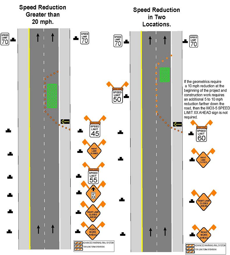
| pdf. version of Fig. 616.29.3.4 |
Fig. 616.29.3.4 Work Zone SPEED LIMIT Locations for Reductions Greater than 20 mph and Reduction in Two Locations
For undivided roadways, provide signs only on the right side of each direction.
For proper speed limit sign spacing, reference typical applications EPG 616.29.3.1 Work Zone Speed Limit Locations within Advance Warning Area or EPG 616.29.3.2 Work Zone Speed Limit Locations within Activity Area.


