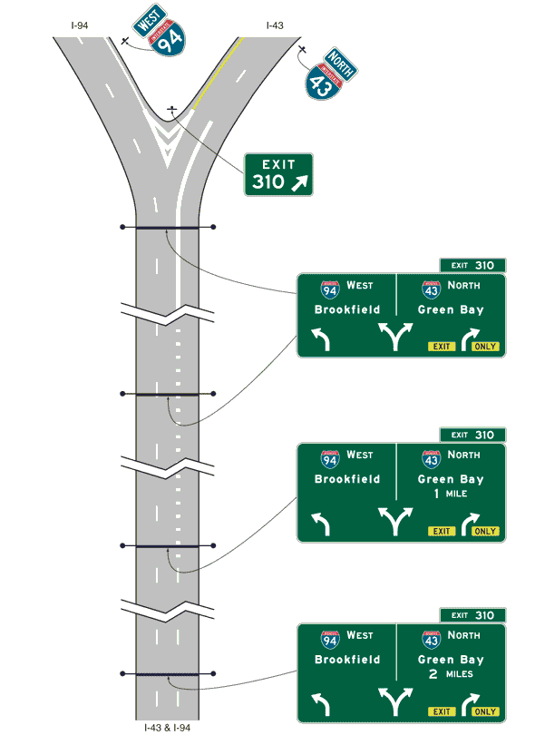
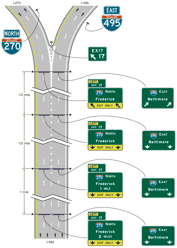
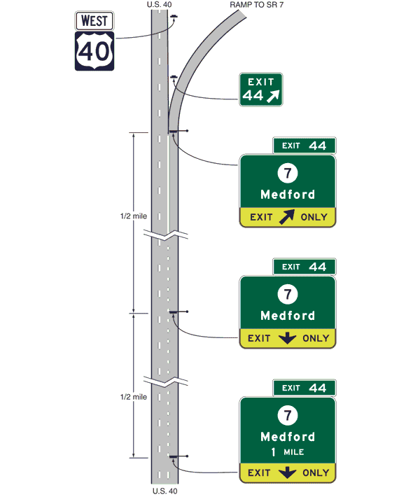
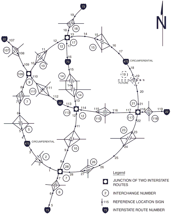
Difference between revisions of "903.8 Freeway and Expressway Guide Signs"
m (→903.8.58 Supplemental Guide Signs for Lakes: updated link) |
|||
| (3 intermediate revisions by the same user not shown) | |||
| Line 1: | Line 1: | ||
[[image:903.8 Freeway and Expressway Guide Signs.jpg|right|350px]] | [[image:903.8 Freeway and Expressway Guide Signs.jpg|right|350px]] | ||
| − | ==903.8.1 Scope of Freeway and Expressway Guide Sign Standards (MUTCD Section 2E.01)== | + | ==903.8.1 Scope of Freeway and Expressway Guide Sign Standards ([https://mutcd.fhwa.dot.gov/ MUTCD] Section 2E.01)== |
'''Support.''' This article provides a uniform and effective system of signing for high-volume, high-speed motor vehicle traffic on freeways and expressways. The requirements and specifications for expressway signing exceed those for conventional roads (see [[903.7 Conventional Road Guide Signs|EPG 903.7]]), but are less than those for freeway signing. Since there are many geometric design variables to be found in existing roads, a signing concept commensurate with prevailing conditions is the primary consideration. Refer to [[:Category:900 TRAFFIC CONTROL#900.1.13 Definitions of Headings, Words and Phrases in the EPG 900 articles (MUTCD Section 1A.13)|EPG 900.1.13 Definitions of Headings, Words and Phrases]] for definitions of freeway and expressway. | '''Support.''' This article provides a uniform and effective system of signing for high-volume, high-speed motor vehicle traffic on freeways and expressways. The requirements and specifications for expressway signing exceed those for conventional roads (see [[903.7 Conventional Road Guide Signs|EPG 903.7]]), but are less than those for freeway signing. Since there are many geometric design variables to be found in existing roads, a signing concept commensurate with prevailing conditions is the primary consideration. Refer to [[:Category:900 TRAFFIC CONTROL#900.1.13 Definitions of Headings, Words and Phrases in the EPG 900 articles (MUTCD Section 1A.13)|EPG 900.1.13 Definitions of Headings, Words and Phrases]] for definitions of freeway and expressway. | ||
| Line 12: | Line 12: | ||
[[image:903.8.2.jpg|right|375px]] | [[image:903.8.2.jpg|right|375px]] | ||
| − | '''Support.''' The development of a signing system for freeways and expressways is approached on the premise that the signing is primarily for the benefit and direction of travelers who are not familiar with the route or area. The signing furnishes travelers with clear instructions for orderly progress to their destinations. Sign installations are an integral part of the facility and, as such, are best planned concurrently with the development of highway location and geometric design. For optimal results, plans for signing are analyzed during the earliest stages of preliminary design and details are correlated as final design is developed. The excessive signing found on many major highways usually is the result of using a multitude of signs that are too small | + | '''Support.''' The development of a signing system for freeways and expressways is approached on the premise that the signing is primarily for the benefit and direction of travelers who are not familiar with the route or area. The signing furnishes travelers with clear instructions for orderly progress to their destinations. Sign installations are an integral part of the facility and, as such, are best planned concurrently with the development of highway location and geometric design. For optimal results, plans for signing are analyzed during the earliest stages of preliminary design and details are correlated as final design is developed. The excessive signing found on many major highways usually is the result of using a multitude of signs that are too small, poorly designed and placed to accomplish the intended purpose. |
Freeway and expressway signing should be considered and developed as a planned system of installations. An engineering study is sometimes necessary for proper solution of the problems of many individual locations, but, in addition, consideration of an entire route is necessary. | Freeway and expressway signing should be considered and developed as a planned system of installations. An engineering study is sometimes necessary for proper solution of the problems of many individual locations, but, in addition, consideration of an entire route is necessary. | ||
| Line 18: | Line 18: | ||
'''Guidance.''' Travelers should be guided with consistent signing on the approaches to interchanges when they drive from one state to another and when driving through rural or urban areas. Because geographical, geometric and operating factors regularly create significant differences between urban and rural conditions, the signing should take these conditions into account. Guide signs on freeways and expressways should serve distinct functions as follows: | '''Guidance.''' Travelers should be guided with consistent signing on the approaches to interchanges when they drive from one state to another and when driving through rural or urban areas. Because geographical, geometric and operating factors regularly create significant differences between urban and rural conditions, the signing should take these conditions into account. Guide signs on freeways and expressways should serve distinct functions as follows: | ||
| − | A. Give directions to destinations, or to streets or highway routes, at intersections or interchanges; | + | :A. Give directions to destinations, or to streets or highway routes, at intersections or interchanges; |
| − | B. Furnish advance notice of the approach to intersections or interchanges; | + | :B. Furnish advance notice of the approach to intersections or interchanges; |
| − | C. Direct travelers into appropriate lanes in advance of diverging or merging movements; | + | :C. Direct travelers into appropriate lanes in advance of diverging or merging movements; |
| − | D. Identify routes and directions on those routes; | + | :D. Identify routes and directions on those routes; |
| − | E. Show distances to destinations; | + | :E. Show distances to destinations; |
| − | F. Indicate access to general motorist services, rest, scenic and recreational areas; and | + | :F. Indicate access to general motorist services, rest, scenic and recreational areas; and |
| − | G. Provide other information of value to the traveler. | + | :G. Provide other information of value to the traveler. |
==903.8.3 General Design (MUTCD Section 2E.04)== | ==903.8.3 General Design (MUTCD Section 2E.04)== | ||
| Line 38: | Line 38: | ||
'''Standard.''' Standard shapes and colors shall be used so that travelers can promptly recognize traffic signs. | '''Standard.''' Standard shapes and colors shall be used so that travelers can promptly recognize traffic signs. | ||
| − | '''Support.''' Guide signs are generally considered to be the white-on-green signs and are normally associated with major highways and interstates. When preparing signing plans, consistency and coordination with existing signing is critical. This does not mean poor signing should be replaced in kind for the sake of consistency. Consistent application of legend styles, abbreviations, control cities, wording, and arrow placement are important for proper driver guidance and expectancy. This is accomplished by routinely applying standards. Signing is basically for the first time driver, not repeat traffic. An example of poor signing would be having two advance guide signs for the same exit listing different control cities. Another example would be using local cities for general guidance instead of standard control cities. It is important to have consistent signing throughout the state of Missouri. | + | '''Support.''' Guide signs are generally considered to be the white-on-green signs and are normally associated with major highways and interstates. When preparing signing plans, consistency and coordination with existing signing is critical. This does not mean poor signing should be replaced in kind for the sake of consistency. Consistent application of legend styles, abbreviations, control cities, wording, and arrow placement are important for proper driver guidance and expectancy. This is accomplished by routinely applying standards. Signing is basically for the first-time driver, not repeat traffic. An example of poor signing would be having two advance guide signs for the same exit listing different control cities. Another example would be using local cities for general guidance instead of standard control cities. It is important to have consistent signing throughout the state of Missouri. |
Guide sign standards in this section and as shown on the standard plans are used whenever possible. Conditions that require deviation from these standards are held to a minimum and justified. Design variances require district justification at the preliminary sign location stage. Signing variances are also noted in the plans. Some deviations from design standards may require approval as outlined in [[131.1 Design Exception Process|EPG 131.1 Design Exception Process]]. | Guide sign standards in this section and as shown on the standard plans are used whenever possible. Conditions that require deviation from these standards are held to a minimum and justified. Design variances require district justification at the preliminary sign location stage. Signing variances are also noted in the plans. Some deviations from design standards may require approval as outlined in [[131.1 Design Exception Process|EPG 131.1 Design Exception Process]]. | ||
| Line 54: | Line 54: | ||
==903.8.5 Retroreflection or Illumination (MUTCD Section 2E.06)== | ==903.8.5 Retroreflection or Illumination (MUTCD Section 2E.06)== | ||
| − | ''Standard.'' Letters, numerals, symbols, arrows, and borders of all guide signs shall be retroreflectorized. The background of all guide signs that are not independently illuminated shall be retroreflective. | + | '''Standard.''' Letters, numerals, symbols, arrows, and borders of all guide signs shall be retroreflectorized. The background of all guide signs that are not independently illuminated shall be retroreflective. |
'''Support.''' Where there is no serious interference from extraneous light sources, retroreflectorized post-mounted signs usually provide adequate nighttime visibility. | '''Support.''' Where there is no serious interference from extraneous light sources, retroreflectorized post-mounted signs usually provide adequate nighttime visibility. | ||
| Line 60: | Line 60: | ||
On freeways and expressways where much driving at night is done with low-beam headlights, the amount of headlight illumination incident to an overhead sign display is relatively small. | On freeways and expressways where much driving at night is done with low-beam headlights, the amount of headlight illumination incident to an overhead sign display is relatively small. | ||
| − | ''' | + | '''Option.''' Overhead sign lighting may be installed based on engineering judgement. Typical installations are limited to signs located in tunnels or under structures. |
| − | '''Support.''' There are two types of reflective | + | '''Support.''' There are two types of reflective sheeting used by MoDOT, (see [https://www.modot.org/standard-plans-section-900 Standard Plans 903]): |
| − | :1) | + | :1) ASTM Type IV Prismatic |
| − | + | :2) ASTM Type IX or XI Prismatic | |
| − | :2) | ||
| − | |||
| − | |||
==903.8.6 Urban Signing Characteristics (MUTCD Section 2E.06)== | ==903.8.6 Urban Signing Characteristics (MUTCD Section 2E.06)== | ||
| Line 74: | Line 71: | ||
'''Support.''' Urban conditions are characterized not so much by city limits or other arbitrary boundaries, as by the following features: | '''Support.''' Urban conditions are characterized not so much by city limits or other arbitrary boundaries, as by the following features: | ||
| − | A. Mainline roadways with more than two lanes in each direction; | + | :A. Mainline roadways with more than two lanes in each direction; |
| − | B. High traffic volumes on the through roadways; | + | :B. High traffic volumes on the through roadways; |
| − | C. High volumes of traffic entering and leaving interchanges; | + | :C. High volumes of traffic entering and leaving interchanges; |
| − | D. Interchanges closely spaced; | + | :D. Interchanges closely spaced; |
| − | E. Roadway and interchange lighting; | + | :E. Roadway and interchange lighting; |
| − | F. Three or more interchanges serving the major city; | + | :F. Three or more interchanges serving the major city; |
| − | G. A loop, circumferential or spur serving a sizable portion of the urban population; and | + | :G. A loop, circumferential or spur serving a sizable portion of the urban population; and |
| − | H. Visual clutter from roadside development. | + | :H. Visual clutter from roadside development. |
Operating conditions and road geometrics on urban freeways and expressways usually make special sign treatments desirable, including: | Operating conditions and road geometrics on urban freeways and expressways usually make special sign treatments desirable, including: | ||
| − | A. Use of Interchange Sequence signs; | + | :A. Use of Interchange Sequence signs; |
| − | B. Use of sign spreading to the maximum extent possible (see EPG 903.8.11); | + | :B. Use of sign spreading to the maximum extent possible (see [[#903.8.11 Designation of Destinations (MUTCD Section 2E.13)|EPG 903.8.11); |
| − | C. Elimination of General | + | :C. Elimination of General or Specific Service signing (see [[903.10 General Service Signs|EPG 903.10 General Service Signs]]); |
| − | D. Reduction to a minimum of post-interchange signs (see [[#903.8.40 Post-Interchange Signs (MUTCD Section 2E.38)|EPG 903.8.40 Post-Interchange Signs]]); | + | :D. Reduction to a minimum of post-interchange signs (see [[#903.8.40 Post-Interchange Signs (MUTCD Section 2E.38)|EPG 903.8.40 Post-Interchange Signs]]); |
| − | E. Display of advance signs at distances closer to the interchange, with appropriate adjustments in the legend (see [[#903.8.34 Advance Guide Signs (MUTCD Section 2E.33)|EPG 903.8.34 Advance Guide Signs]]); | + | :E. Display of advance signs at distances closer to the interchange, with appropriate adjustments in the legend (see [[#903.8.34 Advance Guide Signs (MUTCD Section 2E.33)|EPG 903.8.34 Advance Guide Signs]]); |
| − | F. Use of overhead signs on roadway structures and independent sign supports (see [[#903.8.26 Overhead Sign Installations (MUTCD Section 2E.25)|Overhead Sign Installations]]); | + | :F. Use of overhead signs on roadway structures and independent sign supports (see [[#903.8.26 Overhead Sign Installations (MUTCD Section 2E.25)|Overhead Sign Installations]]); |
| − | G. Use of Overhead Arrow-per-Lane | + | :G. Use of Overhead Arrow-per-Lane guide signs in advance of intersections and interchanges; and |
| − | H. Frequent use of street names as the principal message in guide signs. | + | :H. Frequent use of street names as the principal message in guide signs. |
Lower speeds that are often characteristic of urban operations do not justify lower signing standards. Typical traffic patterns are more complex for the traveler to negotiate and large, easy-to-read legends are, therefore, just as necessary as on rural highways. | Lower speeds that are often characteristic of urban operations do not justify lower signing standards. Typical traffic patterns are more complex for the traveler to negotiate and large, easy-to-read legends are, therefore, just as necessary as on rural highways. | ||
| Line 126: | Line 123: | ||
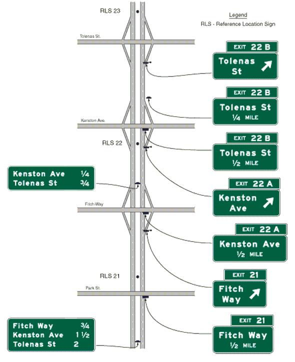
'''Guidance.''' Where overhead signing is used, sign spreading should be used at all single exit interchanges and to the extent possible at multi-exit interchanges. Sign spreading should be accomplished by using the following: | '''Guidance.''' Where overhead signing is used, sign spreading should be used at all single exit interchanges and to the extent possible at multi-exit interchanges. Sign spreading should be accomplished by using the following: | ||
| − | A. The Exit Direction sign should be the only sign used in the vicinity of the gore (other than the Exit Gore sign). It should be located overhead near the theoretical gore and generally on an overhead sign support structure. | + | :A. The Exit Direction sign should be the only sign used in the vicinity of the gore (other than the Exit Gore sign). It should be located overhead near the theoretical gore and generally on an overhead sign support structure. |
| − | B. The Advance Guide sign to indicate the next interchange exit should be placed near the crossroad location. If the crossroad goes over the mainline, the Advance Guide sign should be placed on the overcrossing structure or on a separate structure immediately in front of the overcrossing structure. | + | :B. The Advance Guide sign to indicate the next interchange exit should be placed near the crossroad location. If the crossroad goes over the mainline, the Advance Guide sign should be placed on the overcrossing structure or on a separate structure immediately in front of the overcrossing structure. |
'''Standard.''' No more than three signs shall be placed on any truss for one direction of travel, preferably only two. Only guide signs shall be placed on a truss for one traffic direction. | '''Standard.''' No more than three signs shall be placed on any truss for one direction of travel, preferably only two. Only guide signs shall be placed on a truss for one traffic direction. | ||
| − | + | <div id="Fig. 903.8.9"></div> | |
[[image:Figure 903.8.9.jpg|thumb|center|frame|<center>'''Fig. 903.8.9 Example of Guide Sign Spreading'''</center>]] | [[image:Figure 903.8.9.jpg|thumb|center|frame|<center>'''Fig. 903.8.9 Example of Guide Sign Spreading'''</center>]] | ||
| Line 160: | Line 157: | ||
'''Guidance.''' Control city legends should be used in the following situations along a freeway: | '''Guidance.''' Control city legends should be used in the following situations along a freeway: | ||
| − | A. At interchanges between freeways; | + | :A. At interchanges between freeways; |
| − | B. At separation points of overlapping freeway routes; | + | :B. At separation points of overlapping freeway routes; |
| − | C. On directional signs on intersecting routes, to guide traffic entering the freeway; | + | :C. On directional signs on intersecting routes, to guide traffic entering the freeway; |
| − | D. On Pull-Through signs; and | + | :D. On Pull-Through signs; and |
| − | E. On the bottom line of post-interchange distance signs. | + | :E. On the bottom line of post-interchange distance signs. |
'''Support.''' Continuity of destination names is also useful on expressways serving long-distance or intrastate travel. | '''Support.''' Continuity of destination names is also useful on expressways serving long-distance or intrastate travel. | ||
| − | The determination of major destinations or control cities is important to the quality of service provided by the freeway. Control cities on freeway guide signs are selected by the State and are contained in the ''Guidelines for the Selection of Supplemental Guide Signs for Traffic Generators Adjacent to Freeways, 4th Edition/Guide Signs, Part II: Guidelines for Airport Guide Signing/Guide Signs, Part III: List of Control Cities for Use in Guide Signs on Interstate Highways'', published by and available from the American Association of State and Highway Transportation Officials, see Table 903.8.11. | + | The determination of major destinations or control cities is important to the quality of service provided by the freeway. Control cities on freeway guide signs are selected by the State and are contained in the ''Guidelines for the Selection of Supplemental Guide Signs for Traffic Generators Adjacent to Freeways, 4th Edition/Guide Signs, Part II: Guidelines for Airport Guide Signing/Guide Signs, Part III: List of Control Cities for Use in Guide Signs on Interstate Highways'', published by and available from the American Association of State and Highway Transportation Officials, see Table 903.8.11. Central Office Highway Safety and Traffic Division selects and maintains control cities for each route to maintain consistency in signing across the state. |
| − | Typically, interchanges between freeways and | + | Typically, interchanges between freeways and conventional routes within an urban area identify the exit by the cross-street on the guide signing rather than using control points, control cities, or other community names. |
| − | '''Guidance.''' For interstates, post-interchange distance signs should contain | + | '''Guidance.''' For interstates, post-interchange distance signs should contain three lines. The first line is generally the next destination reached by means of the next interchange, the second line is generally the next significant control city and the third line is generally the anchor control city for the route or section of route. |
In a limited number of locations, the use of the name of a neighboring state or adjacent county might be more relevant. Use of these identifiers should be used sparingly and only if such a designation is in the best interest of the motorists in that region. | In a limited number of locations, the use of the name of a neighboring state or adjacent county might be more relevant. Use of these identifiers should be used sparingly and only if such a designation is in the best interest of the motorists in that region. | ||
| Line 186: | Line 183: | ||
Destination signs with arrows at ramp terminals are not to contain distances. | Destination signs with arrows at ramp terminals are not to contain distances. | ||
| − | '''Standard.''' The last, or in some cases the third line, shall be the next control city, or the control city used consistently throughout the route. If the intersecting road of freeway in an urban area is a state-maintained route, the appropriate route shield shall be used in addition to the street name or control communities displayed. | + | '''Standard.''' The last, or in some cases the third line, shall be the next control city, or the control city used consistently throughout the route. If the intersecting road of a freeway in an urban area is a state-maintained route, the appropriate route shield shall be used in addition to the street name or control communities displayed. |
| − | Destination signs shall not be used on roadways | + | Destination signs shall not be used on roadways which provide interchange sequence signing. |
| − | If used, Advance Destination signs shall be located a minimum of 200 ft. before an intersection or any ramp terminal. | + | If used, Advance Destination signs shall be located a minimum of 200 ft. before an intersection or any ramp terminal. For three-line signs, the destination going straight shall be listed first, with the arrow to the extreme left of the sign. The destination left shall be next with the arrow to the extreme left, and the third line with the destination right, with the arrow to the extreme right. The same order shall be used for two-line destination signs. |
'''Option.''' The second line, if used, may be any significant destination between the next exit and the next control city. | '''Option.''' The second line, if used, may be any significant destination between the next exit and the next control city. | ||
| Line 196: | Line 193: | ||
Advance Destination signs may be eliminated in urban areas where numerous destinations exist, numerous signs exist, or ground mounting space is limited. | Advance Destination signs may be eliminated in urban areas where numerous destinations exist, numerous signs exist, or ground mounting space is limited. | ||
| − | A community within a predominantly rural area that is served by multiple interchanges may identify the interchanges using either the name of the cross-street, the name of the local community or the nearest control | + | A community within a predominantly rural area that is served by multiple interchanges may identify the interchanges using either the name of the cross-street, the name of the local community or the nearest control cities. |
===<center>Table 903.8.11 Interstate Sign Control Cities</center>=== | ===<center>Table 903.8.11 Interstate Sign Control Cities</center>=== | ||
| Line 215: | Line 212: | ||
|- | |- | ||
|44|| Wichita Falls, Lawton, Oklahoma City, Tulsa, Joplin, Springfield, Rolla, St. Louis | |44|| Wichita Falls, Lawton, Oklahoma City, Tulsa, Joplin, Springfield, Rolla, St. Louis | ||
| + | |- | ||
| + | |49|| Joplin, Kansas City | ||
|- | |- | ||
|55|| New Orleans, Hammond, McComb, Jackson, Grenada, Memphis, Blytheville, Sikeston, Cape Girardeau, St. Louis, Chicago | |55|| New Orleans, Hammond, McComb, Jackson, Grenada, Memphis, Blytheville, Sikeston, Cape Girardeau, St. Louis, Chicago | ||
| Line 233: | Line 232: | ||
==903.8.12 Size and Style of Letters and Signs (MUTCD Section 2E.14)== | ==903.8.12 Size and Style of Letters and Signs (MUTCD Section 2E.14)== | ||
| − | '''Standard.''' For all freeway and expressway signs that do not have a standardized design, the message dimensions shall be determined first, and the outside sign dimensions secondarily. Word messages in the legend of expressway guide signs shall be in letters at least 8 inches tall. Larger lettering shall be used for major guide signs at or in advance of interchanges and for all overhead signs. All names of places, streets and highways on freeway and expressway guide signs shall be composed of lower-case letters with initial upper-case letters. The nominal loop height of the lower-case letters shall be ¾ of the height of the initial upper-case letter. Other word legends shall be composed of upper-case letters. Interline and edge spacing shall be as provided in EPG 903.8.13. | + | '''Standard.''' For all freeway and expressway signs that do not have a standardized design, the message dimensions shall be determined first, and the outside sign dimensions secondarily. Word messages in the legend of expressway guide signs shall be in letters at least 8 inches tall. Larger lettering shall be used for major guide signs at or in advance of interchanges and for all overhead signs. All names of places, streets and highways on freeway and expressway guide signs shall be composed of lower-case letters with initial upper-case letters. The nominal loop height of the lower-case letters shall be ¾ of the height of the initial upper-case letter. Other word legends shall be composed of upper-case letters. Interline and edge spacing shall be as provided in [[#903.8.13 Line Spacing (MUTCD Section 2E.15)|EPG 903.8.13]]. |
Lettering size on freeway and expressway signs shall be the same for both rural and urban conditions. | Lettering size on freeway and expressway signs shall be the same for both rural and urban conditions. | ||
| Line 249: | Line 248: | ||
!Advanced Guide | !Advanced Guide | ||
|| E1-1|| [[#903.8.34 Advance Guide Signs (MUTCD Section 2E.33)|903.8.34]]|| -|| -|| -|| Varies | || E1-1|| [[#903.8.34 Advance Guide Signs (MUTCD Section 2E.33)|903.8.34]]|| -|| -|| -|| Varies | ||
| + | |- | ||
| + | !Overhead Arrow-per-Lane | ||
| + | || E1-1|| [[#903.8.22 Design of Overhead Arrow-per-Lane Guide Signs for Option Lanes (MUTCD Section 2E.21)|903.8.22]] | ||
| + | || - || - || - ||Varies | ||
|- | |- | ||
!Exit Hat | !Exit Hat | ||
| Line 254: | Line 257: | ||
|- | |- | ||
!Left | !Left | ||
| − | || E1-5aP|| [[#903.8.25 | + | || E1-5aP|| [[#903.8.25 Lane Reduction and Route Termination |903.8.25]] || -|| -|| -|| 72 X 30 |
|- | |- | ||
!Left Exit | !Left Exit | ||
| − | || E1-5bP|| [[#903.8.25 | + | || E1-5bP|| [[#903.8.25 Lane Reduction and Route Termination |903.8.25]]|| -|| -|| -|| Var X 54 |
| − | |||
| − | |||
| − | |||
| − | |||
| − | |||
| − | |||
|- | |- | ||
!City Exit - Next X Exits | !City Exit - Next X Exits | ||
| − | || E4-1|| [[#903.8. | + | || E4-1|| [[#903.8.45 NEXT XX EXITS Sign (MUTCD Section 2E.42)|903.8.45]] || -|| -|| -|| Varies |
|- | |- | ||
!Next Exit X Miles | !Next Exit X Miles | ||
| − | || E4-2|| [[#903.8. | + | || E4-2|| [[#903.8.35 Next Exit Plaques (MUTCD Section 2E.34)|903.8.35]] || -|| -|| -|| Var X 36 |
|- | |- | ||
| − | ! | + | !Supplemental Guide |
|| E4-3|| [[#903.8.36 Other Supplemental Guide Signs (MUTCD Section 2E.35)|903.8.36]] || -|| -|| -|| Varies | || E4-3|| [[#903.8.36 Other Supplemental Guide Signs (MUTCD Section 2E.35)|903.8.36]] || -|| -|| -|| Varies | ||
|- | |- | ||
| Line 278: | Line 275: | ||
|- | |- | ||
!Exit Gore - With Number | !Exit Gore - With Number | ||
| − | || E5-1a|| [[#903.8.39 Exit Gore Signs (E5-1 Series) (MUTCD Section 2E.37)|903.8.39]]|| -|| -|| -|| Var | + | || E5-1a|| [[#903.8.39 Exit Gore Signs (E5-1 Series) (MUTCD Section 2E.37)|903.8.39]]|| -|| -|| -|| 72 X Var |
|- | |- | ||
!Interchange Sequence | !Interchange Sequence | ||
| Line 302: | Line 299: | ||
'''Guidance.''' Freeway lettering sizes should be used when expressway geometric design is comparable to freeway standards. | '''Guidance.''' Freeway lettering sizes should be used when expressway geometric design is comparable to freeway standards. | ||
| − | Other sign letter size requirements not specifically identified elsewhere in this article should be guided by these specifications | + | Other sign letter size requirements not specifically identified elsewhere in this article should be guided by these specifications. |
'''Support.''' A sign mounted over a particular roadway lane to which it applies might have to be limited in horizontal dimension to the width of the lane, so that another sign can be placed over an adjacent lane. The necessity to maintain proper vertical clearance might also place a further limitation on the size of the overhead sign and the legend that can be accommodated. | '''Support.''' A sign mounted over a particular roadway lane to which it applies might have to be limited in horizontal dimension to the width of the lane, so that another sign can be placed over an adjacent lane. The necessity to maintain proper vertical clearance might also place a further limitation on the size of the overhead sign and the legend that can be accommodated. | ||
| Line 308: | Line 305: | ||
Overhead and ground mounted guide signs are designed with Series E Modified letters, as shown in the Standard Highway Signs manual. If black legend is to be used (such as "EXIT ONLY") the E Modified Series should be chosen. | Overhead and ground mounted guide signs are designed with Series E Modified letters, as shown in the Standard Highway Signs manual. If black legend is to be used (such as "EXIT ONLY") the E Modified Series should be chosen. | ||
| − | Series B through | + | Series B through E Modified is mainly for smaller sheet signs such as: warning, regulatory and route marker signs. The Standard Highway Signs manual shows series and letter heights for these types of signs. |
| − | |||
| − | |||
| − | |||
| − | |||
| − | |||
| − | |||
==903.8.13 Line Spacing (MUTCD Section 2E.15)== | ==903.8.13 Line Spacing (MUTCD Section 2E.15)== | ||
| Line 356: | Line 347: | ||
'''Guidance.''' The use of punctuation is not to be used on structural signing. | '''Guidance.''' The use of punctuation is not to be used on structural signing. | ||
| − | '''Option.''' Exceptions include the use of a solidus (slanted line or forward slash) to separate routes listed on interchange sequence signing | + | '''Option.''' Exceptions include the use of a solidus (slanted line or forward slash) to display fractions, a dash or hyphen to separate routes listed on interchange sequence signing or placed between “I” and the interstate route number on interchange sequence signing, and any punctuation that is part of a proper name such as “Boone’s Lick Rd”. |
==903.8.17 Symbols (MUTCD Section 2E.18)== | ==903.8.17 Symbols (MUTCD Section 2E.18)== | ||
| Line 384: | Line 375: | ||
Type A arrows shall not be placed on signs with EXIT ONLY panels that contain a Type C arrow. Either a Type A or C arrow shall be used, but not both on the same sign. | Type A arrows shall not be placed on signs with EXIT ONLY panels that contain a Type C arrow. Either a Type A or C arrow shall be used, but not both on the same sign. | ||
| − | Multiple arrows shall be used at multilane exits. Multiple 45-degree Type A arrows or any Type C arrows shall always be placed in the bottom line of copy with no other legend | + | Multiple arrows shall be used at multilane exits. Multiple 45-degree Type A arrows or any Type C arrows shall always be placed in the bottom line of copy with no other legend and centered over the appropriate lane or lanes. Standard Type C arrows shall be combined with EXIT ONLY panels when appropriate, as seen in the standard plans. |
| − | When used with an EXIT ONLY panel, multiple Type A arrows shall appear directly above the panel | + | When used with an EXIT ONLY panel, multiple Type A arrows shall appear directly above the panel and shall be spaced horizontally over the center of the appropriate lanes. |
Downward pointing arrows shall not appear on any guide signing in advance of the deceleration lane for exits that are accessed only via a deceleration lane. | Downward pointing arrows shall not appear on any guide signing in advance of the deceleration lane for exits that are accessed only via a deceleration lane. | ||
| Line 409: | Line 400: | ||
Inverted U arrows may be used on Exit Direction or Gore Exit signs when the ramp or exit speed is 30 mph or less. | Inverted U arrows may be used on Exit Direction or Gore Exit signs when the ramp or exit speed is 30 mph or less. | ||
| − | '''Support.''' Directional and down arrows for use on guide signs are shown in [[903.7 Conventional Road Guide Signs#Fig. 903.7.8 Various|Fig. 903.7.8]]. Detailed drawings and standardized sizes based on ranges of letter heights for these arrows will be provided by Central Office Traffic. | + | '''Support.''' Directional and down arrows for use on guide signs are shown in [[903.7 Conventional Road Guide Signs#Fig. 903.7.8 Various|Fig. 903.7.8]]. Detailed drawings and standardized sizes based on ranges of letter heights for these arrows will be provided by Central Office Highway Safety and Traffic. |
==903.8.19 Cardinal Directions== | ==903.8.19 Cardinal Directions== | ||
| Line 425: | Line 416: | ||
Since lettered routes are not designated as being strictly North/South or East/West, the shield does not normally carry a cardinal direction with it. An exception is with a lettered route that has two exits, which would occur at a cloverleaf interchange. The cardinal direction used in this case should be the direction physically associated with the route. | Since lettered routes are not designated as being strictly North/South or East/West, the shield does not normally carry a cardinal direction with it. An exception is with a lettered route that has two exits, which would occur at a cloverleaf interchange. The cardinal direction used in this case should be the direction physically associated with the route. | ||
| − | Multiple shields for overlapping roadways should be arranged in the following order of importance: interstate, interstate business, U.S. | + | Multiple shields for overlapping roadways should be arranged in the following order of importance: interstate, interstate business, U.S. Routes, U.S. business, Missouri numbered and Missouri lettered. Multiple shields for the same roadway type (i.e. I-35 and I-70, or U.S. 34 and U.S. 67) should be arranged in numerical order starting with the lowest numbered route. For lettered routes, the shields should be arranged in alphabetical order. |
When several routes end at a ramp terminal, all guide sign shields should be arranged as the traveler views the routes at the ramp terminal, from left to right. Cardinal directions are not required. | When several routes end at a ramp terminal, all guide sign shields should be arranged as the traveler views the routes at the ramp terminal, from left to right. Cardinal directions are not required. | ||
| Line 441: | Line 432: | ||
An example of how to sign without the use of a cardinal direction for multiple shields, at a directional ramp split: to the left is Route U and to the right are overlapping Routes A and U.S. Route 47. On the first line of copy, the guide sign shows the Route U shield first, then the U.S. Route 47 shield next to the Route A shield. This impresses upon the motorists to turn left for Route U. The space between the U.S. Route 47 and the Route A shields may be narrowed from the standard 12 in. to as low as 6 in. to give the impression of unity. The space between the Route U shield and the U.S. Route 47 shield is a minimum of 24 in. to give the impression of separation. | An example of how to sign without the use of a cardinal direction for multiple shields, at a directional ramp split: to the left is Route U and to the right are overlapping Routes A and U.S. Route 47. On the first line of copy, the guide sign shows the Route U shield first, then the U.S. Route 47 shield next to the Route A shield. This impresses upon the motorists to turn left for Route U. The space between the U.S. Route 47 and the Route A shields may be narrowed from the standard 12 in. to as low as 6 in. to give the impression of unity. The space between the Route U shield and the U.S. Route 47 shield is a minimum of 24 in. to give the impression of separation. | ||
| − | + | An example of how to use a cardinal direction for multiple shields: an exit to the right for overlapping Routes I-64 and Route 40 is ordered as I-64, Route 40, with one cardinal direction "EAST" placed to the right of the Route 40 shield. | |
==903.8.20 Sign Size Management== | ==903.8.20 Sign Size Management== | ||
| Line 451: | Line 442: | ||
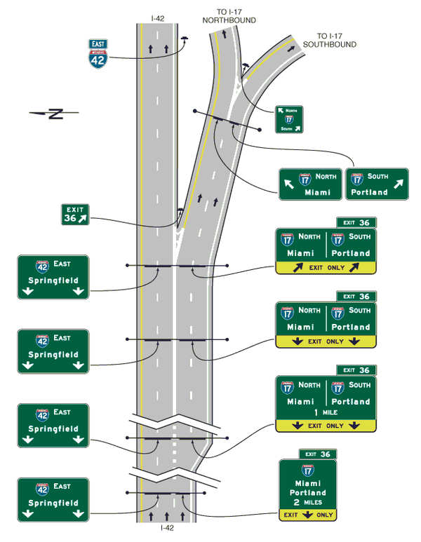
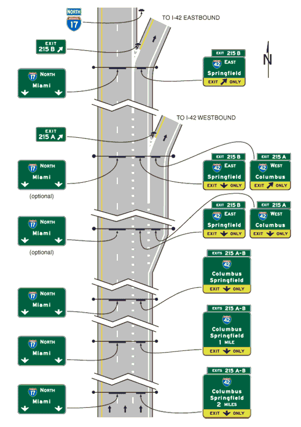
'''Support.''' Some freeway and expressway splits or multi-lane exit interchanges contain an interior option lane serving both movements in which traffic can either leave the route or remain on the route, or choose either destination at a split, from the same lane. | '''Support.''' Some freeway and expressway splits or multi-lane exit interchanges contain an interior option lane serving both movements in which traffic can either leave the route or remain on the route, or choose either destination at a split, from the same lane. | ||
| − | '''Standard.''' On freeways and expressways, either the Overhead Arrow-per-Lane or Diagrammatic guide sign designs as provided in EPG 903.8.22 and EPG 903.8.23 shall be used for all multi-lane exits at major interchanges that have an optional exit lane that also carries the through route and for all splits that include an option lane. Overhead Arrow-per-Lane or Diagrammatic guide signs shall not be used on freeways and expressways for any other types of exits or splits, including single-lane exits and splits that do not have an option lane. | + | '''Standard.''' On freeways and expressways, either the Overhead Arrow-per-Lane or Diagrammatic guide sign designs as provided in EPG 903.8.22 and [[#903.8.23 Design of Freeway and Expressway Diagrammatic Guide Signs for Option Lanes (MUTCD Section 2E.22)|EPG 903.8.23]] shall be used for all multi-lane exits at major interchanges that have an optional exit lane that also carries the through route and for all splits that include an option lane. Overhead Arrow-per-Lane or Diagrammatic guide signs shall not be used on freeways and expressways for any other types of exits or splits, including single-lane exits and splits that do not have an option lane. |
'''Guidance.''' The Overhead Arrow-per-Lane guide sign design should also be considered for multi-lane exits with an option lane at interchanges based on such factors as the extent of the need to optimize the mainline operation by maximizing the usage of the option lane, the extent of the period(s) of the day during which the exiting volumes warrant the multi-lane exit arrangement, and the nature of the traffic that primarily uses the option lane during the high-volume periods. | '''Guidance.''' The Overhead Arrow-per-Lane guide sign design should also be considered for multi-lane exits with an option lane at interchanges based on such factors as the extent of the need to optimize the mainline operation by maximizing the usage of the option lane, the extent of the period(s) of the day during which the exiting volumes warrant the multi-lane exit arrangement, and the nature of the traffic that primarily uses the option lane during the high-volume periods. | ||
| Line 461: | Line 452: | ||
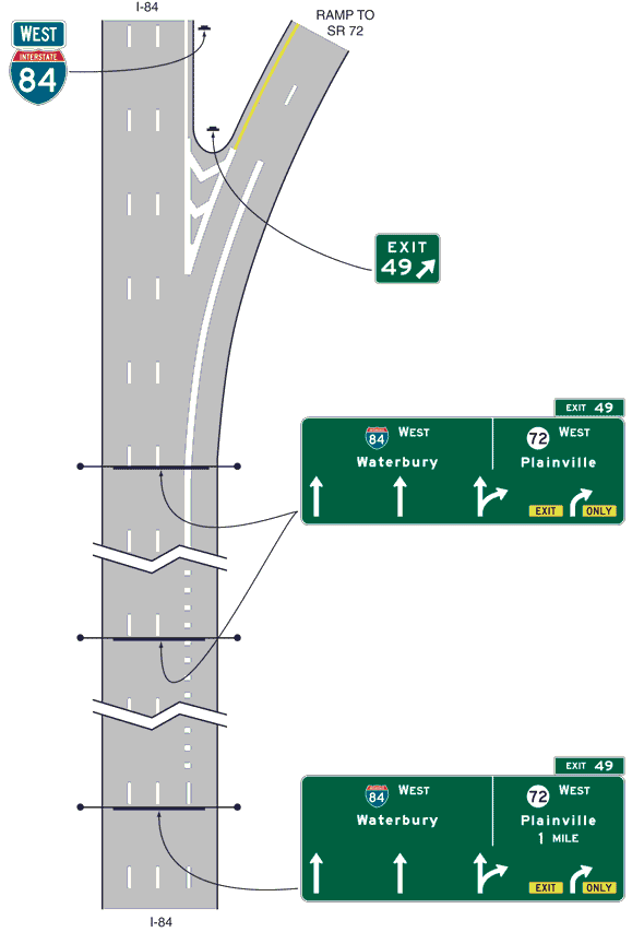
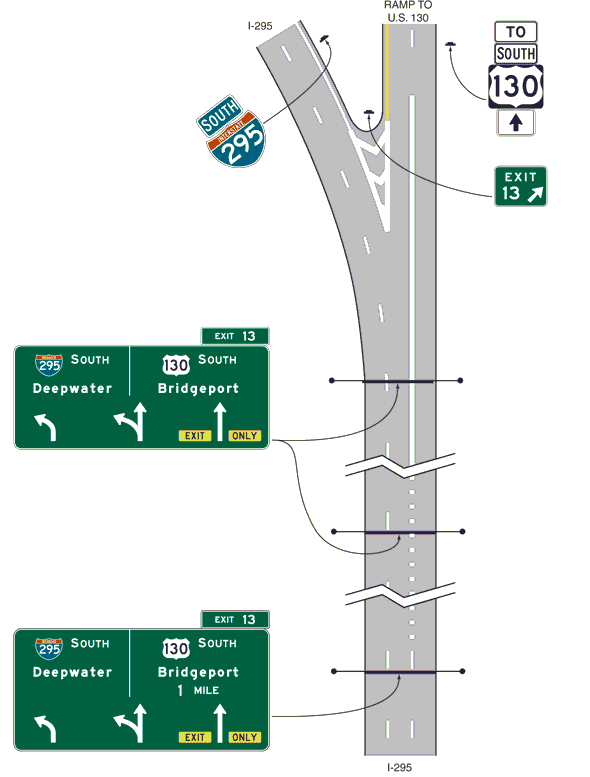
'''Support.''' Overhead Arrow-per-Lane guide signs are used where an option lane is present at freeway and expressway multi-lane exit interchanges and splits. They display an upward-pointing arrow above each lane that conveys the direction(s) of travel that the lane serves at the point of departure. At locations where an option lane is present at a multi-lane exit or split, Overhead Arrow-per-Lane guide signs have been shown to be superior to either conventional guide signs or Diagrammatic guide signs because they convey positive direction about which destination and direction each approach lane serves, particularly for the option lane, which is otherwise difficult to clearly sign. | '''Support.''' Overhead Arrow-per-Lane guide signs are used where an option lane is present at freeway and expressway multi-lane exit interchanges and splits. They display an upward-pointing arrow above each lane that conveys the direction(s) of travel that the lane serves at the point of departure. At locations where an option lane is present at a multi-lane exit or split, Overhead Arrow-per-Lane guide signs have been shown to be superior to either conventional guide signs or Diagrammatic guide signs because they convey positive direction about which destination and direction each approach lane serves, particularly for the option lane, which is otherwise difficult to clearly sign. | ||
| − | '''Standard.''' Overhead Arrow-per-Lane guide signs shall be used on all new or reconstructed freeways and expressways as described in EPG 903.8.21. | + | '''Standard.''' Overhead Arrow-per-Lane guide signs shall be used on all new or reconstructed freeways and expressways as described in [[#903.8.21 Signing for Option Lanes at Splits and Multi-Lane Exits (MUTCD Section 2E.20)|EPG 903.8.21]]. |
Where used, the Overhead Arrow-per-Lane guide sign at the exit or split shall be located at or in the immediate vicinity of the point where the exiting lanes begin to diverge from the through lanes or, for a split, at the point where the approach lanes begin to diverge from one another, preserving the relation of the arrows displayed on the sign to their respective lanes. The Overhead Arrow-per-Lane guide sign at the exit shall not be located at or near the theoretical gore. | Where used, the Overhead Arrow-per-Lane guide sign at the exit or split shall be located at or in the immediate vicinity of the point where the exiting lanes begin to diverge from the through lanes or, for a split, at the point where the approach lanes begin to diverge from one another, preserving the relation of the arrows displayed on the sign to their respective lanes. The Overhead Arrow-per-Lane guide sign at the exit shall not be located at or near the theoretical gore. | ||
| Line 473: | Line 464: | ||
'''Standard.''' Overhead Arrow-per-Lane guide signs used on freeways and expressways shall include one arrow above each lane and shall be designed in accordance with the following criteria: | '''Standard.''' Overhead Arrow-per-Lane guide signs used on freeways and expressways shall include one arrow above each lane and shall be designed in accordance with the following criteria: | ||
| − | A. The sign shall include an upward-pointing arrow for each lane of the approach to the split or exit, and the shaft of each arrow shall be located approximately over the center of the lane to which it applies. | + | :A. The sign shall include an upward-pointing arrow for each lane of the approach to the split or exit, and the shaft of each arrow shall be located approximately over the center of the lane to which it applies. |
| − | B. Arrows for continuing through lanes shall be vertically upward pointing (see Fig. 903.8.22.1) unless those lanes are on a significantly curved alignment beyond the theoretical gore, in which case the arrows for the continuing through lanes shall indicate the approximate degree of curvature (see Fig. 903.8.22.2). | + | :B. Arrows for continuing through lanes shall be vertically upward pointing (see Fig. 903.8.22.1) unless those lanes are on a significantly curved alignment beyond the theoretical gore, in which case the arrows for the continuing through lanes shall indicate the approximate degree of curvature (see Fig. 903.8.22.2). |
| − | C. The arrow for a lane that must exit shall be curved in the direction of the exit and shall be accompanied by black-on-yellow EXIT (E11-1a) and ONLY (E11-1b) sign panels adjacent to the lower end of the arrow shaft. The E11-1a and E11-1b sign panels shall not be used for a split of two overlapping routes where neither of the diverging routes is designated as an exit. Where the through lanes curve and the exit continues on a straight alignment, upward-pointing vertical arrows shall be used for the exiting movement and curved arrows for the through movement. | + | :C. The arrow for a lane that must exit shall be curved in the direction of the exit and shall be accompanied by black-on-yellow EXIT (E11-1a) and ONLY (E11-1b) sign panels adjacent to the lower end of the arrow shaft. The E11-1a and E11-1b sign panels shall not be used for a split of two overlapping routes where neither of the diverging routes is designated as an exit. Where the through lanes curve and the exit continues on a straight alignment, upward-pointing vertical arrows shall be used for the exiting movement and curved arrows for the through movement. |
| − | D. The arrow for an optional exit lane that also carries the through route shall have a single shaft that bifurcates into a vertically upward-pointing arrow and a curving arrow corresponding to the configuration of the through and exit lanes. | + | :D. The arrow for an optional exit lane that also carries the through route shall have a single shaft that bifurcates into a vertically upward-pointing arrow and a curving arrow corresponding to the configuration of the through and exit lanes. |
| − | E. For splits with an option lane, the arrow for the lane from which either direction of the split can be accessed shall have a single shaft that bifurcates into two upward-pointing curving arrows showing the approximate degrees of curvature of the two roadways beyond the theoretical gore (see Fig. 903.8.22.3). | + | :E. For splits with an option lane, the arrow for the lane from which either direction of the split can be accessed shall have a single shaft that bifurcates into two upward-pointing curving arrows showing the approximate degrees of curvature of the two roadways beyond the theoretical gore (see Fig. 903.8.22.3). |
| − | F. A vertical white line shall be used to separate the route shields and destinations for the two diverging movements from each other. | + | :F. A vertical white line shall be used to separate the route shields and destinations for the two diverging movements from each other. |
| − | G. The distance to the exit or split shall be displayed below the off-movement destination on the advance signs at the 1-mile and 2-mile locations. | + | :G. The distance to the exit or split shall be displayed below the off-movement destination on the advance signs at the 1-mile and 2-mile locations. |
| − | H. The number of lanes displayed on a sign shall correspond to the number of lanes at the location of that sign. An advance sign shall not depict lanes that are added downstream of a sign location. | + | :H. The number of lanes displayed on a sign shall correspond to the number of lanes at the location of that sign. An advance sign shall not depict lanes that are added downstream of a sign location. |
| − | I. For numbered exits, the Exit Number (E1-5P) or Left Exit Number (E1-5bP) plaque shall be used at the top of the sign in accordance with EPG 903.8.32. For unnumbered left exits, the LEFT (E1-5aP) plaque shall be used at the top left edge of the sign. | + | :I. For numbered exits, the Exit Number (E1-5P) or Left Exit Number (E1-5bP) plaque shall be used at the top of the sign in accordance with [[#903.8.32 Interchange Exit Numbering (MUTCD Section 2E.31)|EPG 903.8.32]]. For unnumbered left exits, the LEFT (E1-5aP) plaque shall be used at the top left edge of the sign. |
'''Guidance.''' Overhead Arrow-per-Lane guide signs used on freeways and expressways should be designed in accordance with the following additional criteria: | '''Guidance.''' Overhead Arrow-per-Lane guide signs used on freeways and expressways should be designed in accordance with the following additional criteria: | ||
| − | A. No more than one destination should be displayed for each movement, and no more than two destinations should be displayed per sign. | + | :A. No more than one destination should be displayed for each movement, and no more than two destinations should be displayed per sign. |
| − | B. The arrowhead(s) for the diverging movement should be positioned lower on the sign than the arrowhead(s) for the movement that continues straight ahead, independent of which movement carries the through route. Where the movements are freeway or expressway splits rather than exits, the arrowheads should be positioned at approximately the same height on the sign. | + | :B. The arrowhead(s) for the diverging movement should be positioned lower on the sign than the arrowhead(s) for the movement that continues straight ahead, independent of which movement carries the through route. Where the movements are freeway or expressway splits rather than exits, the arrowheads should be positioned at approximately the same height on the sign. |
| − | C. Route shields, cardinal directions, and destinations should be positioned on the sign such that they are clearly related to the arrowhead(s) for the movement to which they apply. | + | :C. Route shields, cardinal directions, and destinations should be positioned on the sign such that they are clearly related to the arrowhead(s) for the movement to which they apply. |
| − | D. The cardinal direction should be placed adjacent to the route shield for exits or splits leading in a single cardinal direction. | + | :D. The cardinal direction should be placed adjacent to the route shield for exits or splits leading in a single cardinal direction. |
| − | E. The vertical white line that is used to separate the route shields and destinations for the two diverging movements from each other should not descend below the top of the arrowheads for the through lanes, and should be positioned approximately halfway between the diverging arrowheads for the optional movement lane. | + | :E. The vertical white line that is used to separate the route shields and destinations for the two diverging movements from each other should not descend below the top of the arrowheads for the through lanes, and should be positioned approximately halfway between the diverging arrowheads for the optional movement lane. |
'''Standard.''' Overhead Arrow-per-Lane guide signs shall not be used to depict a downstream split of an exit ramp on a sign located on the mainline. | '''Standard.''' Overhead Arrow-per-Lane guide signs shall not be used to depict a downstream split of an exit ramp on a sign located on the mainline. | ||
| − | '''Support.''' Specific detailed design of Overhead Arrow-per-Lane guide signs will be provided by Central Office Traffic. | + | '''Support.''' Specific detailed design of Overhead Arrow-per-Lane guide signs will be provided by Central Office Highway Safety and Traffic. |
'''Option.''' Where extra emphasis of an especially low advisory ramp speed is needed, an EXIT XX MPH (E13-2) sign panel may be placed below the applicable destination legend to supplement, but not to replace, the exit or ramp advisory speed warning signs. | '''Option.''' Where extra emphasis of an especially low advisory ramp speed is needed, an EXIT XX MPH (E13-2) sign panel may be placed below the applicable destination legend to supplement, but not to replace, the exit or ramp advisory speed warning signs. | ||
| − | + | <div id="Fig. 903.8.22.1"></div> | |
[[image:903.8.22.1.jpg|center|600px|thumb|<center>'''Fig. 903.8.22.1, Overhead Arrow-per-Lane Guide Signs for a Two-Lane Exit to the Right with an Option Lane'''</center>]] | [[image:903.8.22.1.jpg|center|600px|thumb|<center>'''Fig. 903.8.22.1, Overhead Arrow-per-Lane Guide Signs for a Two-Lane Exit to the Right with an Option Lane'''</center>]] | ||
| Line 518: | Line 509: | ||
==903.8.23 Design of Freeway and Expressway Diagrammatic Guide Signs for Option Lanes (MUTCD Section 2E.22)== | ==903.8.23 Design of Freeway and Expressway Diagrammatic Guide Signs for Option Lanes (MUTCD Section 2E.22)== | ||
| − | '''Support.''' | + | '''Support.''' MoDOT no longer uses diagrammatic signs for option lanes. Overhead arrow-per-lane guide signs are used exclusively for this purpose. |
| − | |||
| − | |||
| − | |||
| − | |||
| − | |||
| − | |||
| − | |||
| − | |||
| − | |||
| − | |||
| − | |||
| − | |||
| − | |||
| − | |||
| − | |||
| − | |||
| − | |||
| − | |||
| − | |||
| − | |||
| − | |||
| − | |||
| − | |||
| − | |||
| − | |||
| − | |||
| − | |||
| − | |||
| − | |||
| − | |||
| − | |||
| − | |||
| − | |||
| − | |||
| − | |||
| − | |||
| − | |||
| − | |||
| − | |||
| − | |||
| − | |||
| − | |||
| − | |||
| − | |||
| − | |||
| − | |||
| − | |||
| − | |||
| − | |||
| − | |||
| − | |||
| − | |||
| − | |||
| − | |||
| − | |||
| − | |||
| − | |||
| − | |||
| − | |||
| − | |||
| − | |||
| − | |||
| − | |||
| − | |||
| − | |||
| − | |||
| − | |||
| − | |||
| − | |||
| − | |||
| − | |||
| − | |||
==903.8.24 Signing for Interchange Lane Drops (MUTCD Section 2E.24)== | ==903.8.24 Signing for Interchange Lane Drops (MUTCD Section 2E.24)== | ||
| − | '''Standard.''' The provisions of this section shall only apply to lane drops at exits that do not have an optional exit lane. At exits that have an optional exit lane in addition to the dropped lane, | + | '''Standard.''' The provisions of this section shall only apply to lane drops at exits that do not have an optional exit lane. At exits that have an optional exit lane in addition to the dropped lane, [[#903.8.21 Signing for Option Lanes at Splits and Multi-Lane Exits (MUTCD Section 2E.20)|EPG 903.8.21]] and [[#903.8.22 Design of Overhead Arrow-per-Lane Guide Signs for Option Lanes (MUTCD Section 2E.21)|EPG 903.8.22]] shall apply. |
| − | |||
| − | |||
| − | + | Major guide signs for all lane drops at interchanges shall be mounted overhead. An EXIT ONLY sign panel shall be used for all interchange lane drops at which the through route is carried on the mainline and when a continuous lane is dropped at an interchange, and the lane being dropped is a minimum of 1000 ft. long from full lane width to the driving pavement exit gore point. | |
| + | Except on Overhead Arrow-per-Lane guide signs, the EXIT ONLY (down arrow) (E3-3) sign panel shall be used on all signing of lane drops on all overhead Advance Guide signs and appropriate Exit Direction signs (see Figs. 903.8.24.1 through 903.8.24.3). The number of arrows on each sign shall correspond to the number of dropped lanes at the location of each sign. Placement of the down arrow shall comply with [[#903.8.18 Arrows for Interchange Guide Signs (MUTCD Section 2E.19)|EPG 903.8.18]]. | ||
| + | <div id="Fig. 903.8.24.1"></div> | ||
[[image:903.8.24.1.jpg|thumb|<center>'''Fig. 903.8.24.1, Guide Signs for a Split with Dedicated Lanes'''</center>|600px]] | [[image:903.8.24.1.jpg|thumb|<center>'''Fig. 903.8.24.1, Guide Signs for a Split with Dedicated Lanes'''</center>|600px]] | ||
| − | + | <div id="Fig. 903.8.24.2"></div> | |
[[image:903.8.24.2.jpg|thumb|<center>'''Fig. 903.8.24.2, Guide Signs for a Single Lane Exit to the Left with a Dropped Lane'''</center>|600px]] | [[image:903.8.24.2.jpg|thumb|<center>'''Fig. 903.8.24.2, Guide Signs for a Single Lane Exit to the Left with a Dropped Lane'''</center>|600px]] | ||
[[image:903.8.24.3.jpg|thumb|<center>'''Fig. 903.8.24.3, Guide Signs for a Single Lane Exit to the Right with a Dropped Lane'''</center>|600px]] | [[image:903.8.24.3.jpg|thumb|<center>'''Fig. 903.8.24.3, Guide Signs for a Single Lane Exit to the Right with a Dropped Lane'''</center>|600px]] | ||
| − | + | '''Option.''' The EXIT ONLY message may also be used in a situation where the lane being dropped is less than 1,000 ft. long where the terminus of the lane is not visible to the driver. | |
| − | '''Option.''' The EXIT ONLY message may also be used in a situation | ||
'''Standard.''' EXIT ONLY legends shall only be used on overhead signs and be centered over the lane being dropped. For lane drops, the Exit Direction sign shall be of the format shown in Figs. 903.8.24.2 and 903.8.24.3. The bottom portion of the Exit Direction sign shall be fluorescent yellow with a black border and shall include a diagonally upward-pointing black directional arrow (left or right) for each lane dropped at the exit, with the sign designed and placed so that each arrow is located over the approximate center of each lane being dropped. The words EXIT and ONLY shall be positioned to the left and right, respectively, of the arrow on the E11-1d sign panel for a single-lane drop. For a two-lane drop, the words EXIT ONLY shall be located between the two arrows on the E11-1e sign panel. The number of arrows on the sign shall correspond to the number of dropped lanes at the location of the sign. | '''Standard.''' EXIT ONLY legends shall only be used on overhead signs and be centered over the lane being dropped. For lane drops, the Exit Direction sign shall be of the format shown in Figs. 903.8.24.2 and 903.8.24.3. The bottom portion of the Exit Direction sign shall be fluorescent yellow with a black border and shall include a diagonally upward-pointing black directional arrow (left or right) for each lane dropped at the exit, with the sign designed and placed so that each arrow is located over the approximate center of each lane being dropped. The words EXIT and ONLY shall be positioned to the left and right, respectively, of the arrow on the E11-1d sign panel for a single-lane drop. For a two-lane drop, the words EXIT ONLY shall be located between the two arrows on the E11-1e sign panel. The number of arrows on the sign shall correspond to the number of dropped lanes at the location of the sign. | ||
| − | New EXIT ONLY legends shall be placed within the white border of the guide sign. This panel shall span the entire sign width along the bottom of a guide sign | + | New EXIT ONLY legends shall be placed within the white border of the guide sign. This panel shall span the entire sign width along the bottom of a guide sign. |
Where an exit only situation exists but overhead signing of the exit only is not possible the RIGHT LANE EXIT ONLY (E11-2st) sign shall be used. | Where an exit only situation exists but overhead signing of the exit only is not possible the RIGHT LANE EXIT ONLY (E11-2st) sign shall be used. | ||
| Line 633: | Line 551: | ||
Wherever the dropped lane carries the through route, signs should be used without the EXIT ONLY sign panel. | Wherever the dropped lane carries the through route, signs should be used without the EXIT ONLY sign panel. | ||
| − | ==903.8.25 | + | ==903.8.25 Lane Reduction and Route Termination== |
'''Guidance.''' When a lane is dropped on a multi-lane, high-volume, high-speed roadway by merging lanes (lane not dropped at an interchange), at least two overhead advance signs should be used. The first sign should indicate the lane that ends and a distance. | '''Guidance.''' When a lane is dropped on a multi-lane, high-volume, high-speed roadway by merging lanes (lane not dropped at an interchange), at least two overhead advance signs should be used. The first sign should indicate the lane that ends and a distance. | ||
| Line 639: | Line 557: | ||
The last sign should indicate the lane that ends and an action line. | The last sign should indicate the lane that ends and an action line. | ||
| − | These signs should be black legend on fluorescent yellow background | + | These signs should be black legend on fluorescent yellow background and placed over the lane that is ending. These signs should have 12 in. series E Modified letters, all upper-case. |
'''Support.''' For example, the first line may read RIGHT LANE ENDS. The second line should provide a distance in feet or mileage such as "1000 FT" or "1/2 MILE". When sufficient distance is available, two advance distance signs are provided at 1 mile and 1/2 mile. | '''Support.''' For example, the first line may read RIGHT LANE ENDS. The second line should provide a distance in feet or mileage such as "1000 FT" or "1/2 MILE". When sufficient distance is available, two advance distance signs are provided at 1 mile and 1/2 mile. | ||
| − | + | Another example, the first line states RIGHT LANE ENDS, and the second line may read "MERGE LEFT". | |
| + | |||
| + | For typical 4-lane to 2-lane reductions see [[903.16 Typical Signing Applications|EPG 903.16 Typical Signing Applications]]. | ||
| − | + | ===903.8.25.1 Signing for Route Termination=== | |
| + | '''Standard.''' In advance of the termination of any route, a sign shall be installed to indicate the route ends and all traffic must exit. The sign shall include the shield of the route, which terminates with a relevant text message, such as “ALL VEHICLES MUST EXIT”. | ||
| + | |||
| + | ===903.8.25.2 Signing for Route Name Change=== | ||
| + | '''Standard.''' In advance of the location where a route name changes, a sign shall be erected indicating “(Rte. XXX) Ends Continue on (Rte. YYY)”. If Route XXX and YYY use different cardinal directions, then they should be included as modifiers to the route shields. | ||
| + | |||
| + | '''Support.''' For termination of conventional roads see [[903.7 Conventional Road Guide Signs#903.7.20 END Auxiliary Sign (M4-6) (MUTCD Section 2D.22)|EPG 903.7.20]]. | ||
==903.8.26 Overhead Sign Installations (MUTCD Section 2E.25)== | ==903.8.26 Overhead Sign Installations (MUTCD Section 2E.25)== | ||
| − | '''Support.''' Specifications for the design and construction of structural supports for signs have been standardized by the American Association of State Highway and Transportation Officials (AASHTO). Overcrossing structures can often serve for the support of overhead signs | + | '''Support.''' Specifications for the design and construction of structural supports for signs have been standardized by the American Association of State Highway and Transportation Officials (AASHTO). Overcrossing structures can often serve for the support of overhead signs and might in some cases be the only practical location that will provide adequate viewing distance. Use of these structures as sign supports will eliminate the need for additional sign supports along the roadside. Factors justifying the installation of overhead signs and installation information are given in [[903.4 Overhead Guide Sign Mounting#903.4.1 Overhead Sign Installations (MUTCD Section 2A.17)|EPG 903.4.1 Overhead Sign Installations]]. Vertical clearance of overhead signs is also discussed in [[903.4 Overhead Sign Mounting#903.4.1 Overhead Sign Installations (MUTCD Section 2A.17)|EPG 903.4.1]]. |
==903.8.27 Lateral Offset (MUTCD Section 2E.26)== | ==903.8.27 Lateral Offset (MUTCD Section 2E.26)== | ||
| − | '''Standard.''' The minimum lateral offset outside the usable roadway shoulder for post-mounted freeway and expressway signs or for overhead sign supports, either to the right-hand or left-hand side of the roadway, shall be 6 feet. | + | '''Standard.''' The minimum lateral offset outside the usable roadway shoulder for post-mounted freeway and expressway signs or for overhead sign supports, either to the right-hand or left-hand side of the roadway, shall be a minimum of 6 feet, see Standard Plans 903. This minimum clearance shall also apply outside of a curb. If located within the clear zone, the signs shall be mounted on crashworthy supports. |
| − | '''Guidance.''' Where practical, a sign should not be less than | + | '''Guidance.''' Where practical, a sign should not be less than 12 ft. from the edge of the nearest traffic lane. |
Where an expressway median is 12 ft. or less in width, consideration should be given to spanning both roadways without a center support. | Where an expressway median is 12 ft. or less in width, consideration should be given to spanning both roadways without a center support. | ||
| Line 661: | Line 587: | ||
Where overhead sign supports cannot be placed sufficiently far away from the line of traffic or in an otherwise protected site, they should either be designed to minimize the impact forces or be adequately shielded by a traffic barrier of suitable design. | Where overhead sign supports cannot be placed sufficiently far away from the line of traffic or in an otherwise protected site, they should either be designed to minimize the impact forces or be adequately shielded by a traffic barrier of suitable design. | ||
| − | '''Standard.''' Butterfly-type sign supports and other overhead | + | '''Standard.''' Butterfly-type sign supports and other overhead non-crashworthy sign supports shall not be installed in gores or other unshielded locations within the clear zone. |
'''Option.''' Lesser clearances, but not generally less than 6 ft., may be used on connecting roadways or ramps at interchanges. | '''Option.''' Lesser clearances, but not generally less than 6 ft., may be used on connecting roadways or ramps at interchanges. | ||
| Line 669: | Line 595: | ||
'''Support.''' Freeway and expressway guide signs are classified and treated in the following categories: | '''Support.''' Freeway and expressway guide signs are classified and treated in the following categories: | ||
| − | A. Route signs and Trailblazer Assemblies; | + | :A. Route signs and Trailblazer Assemblies; |
| − | B. At Grade Intersection signs; | + | :B. At Grade Intersection signs; |
| − | C. Interchange signs; | + | :C. Interchange signs; |
| − | D. Interchange Sequence signs; | + | :D. Interchange Sequence signs; |
| − | E. Community Interchanges Identification signs; | + | :E. Community Interchanges Identification signs; |
| − | F. NEXT XX EXITS signs; | + | :F. NEXT XX EXITS signs; |
| − | G. General Service signs; | + | :G. General Service signs; |
| − | H. Rest and Scenic Area signs; | + | :H. Rest and Scenic Area signs; |
| − | I. Tourist Information and Welcome Center signs; | + | :I. Tourist Information and Welcome Center signs; |
| − | J. Reference Location signs; | + | :J. Reference Location signs; |
| − | K. Miscellaneous information signs; | + | :K. Miscellaneous information signs; |
| − | L. Radio Information signing; | + | :L. Radio Information signing; |
| − | M. Carpool and Ridesharing signing; | + | :M. Carpool and Ridesharing signing; |
| − | N. Weigh Station signing; | + | :N. Weigh Station signing; |
| − | O. Specific Service signs; and | + | :O. Specific Service signs; and |
| − | P. Recreational and Cultural Interest Area signs. | + | :P. Recreational and Cultural Interest Area signs. |
==903.8.29 Route Signs and Trailblazer Assemblies (MUTCD Section 2E.27)== | ==903.8.29 Route Signs and Trailblazer Assemblies (MUTCD Section 2E.27)== | ||
| Line 707: | Line 633: | ||
'''Guidance.''' Route signs should be incorporated as cut-out shields or other distinctive shapes on large directional guide signs. Where the Interstate shield is displayed in an assembly or on the face of a guide sign with U.S. or state route signs, the interstate numeral should be at least equal in size to the numerals on the other Route signs. The use of independent Route signs should be limited primarily to route confirmation assemblies. | '''Guidance.''' Route signs should be incorporated as cut-out shields or other distinctive shapes on large directional guide signs. Where the Interstate shield is displayed in an assembly or on the face of a guide sign with U.S. or state route signs, the interstate numeral should be at least equal in size to the numerals on the other Route signs. The use of independent Route signs should be limited primarily to route confirmation assemblies. | ||
| − | Route signs and auxiliary signs showing junctions and turns should be used for guidance on approach roads | + | Route signs and auxiliary signs showing junctions and turns should be used for guidance on approach roads and for route confirmation just beyond entrances for reassurance along the freeway or expressway. |
Only standard sizes should be used for guide signs and independent use. | Only standard sizes should be used for guide signs and independent use. | ||
| Line 713: | Line 639: | ||
Route shields should be placed before street names and destinations, usually in the first line of the legend. | Route shields should be placed before street names and destinations, usually in the first line of the legend. | ||
| − | + | '''Support.''' Shields are detailed in the standard plans. Numbered primary, U.S. and interstate route shields have two widths available for each type of mount: one for two-digit routes and one for three-digit routes. | |
| − | |||
| − | '''Support.''' Shields are detailed in the standard plans. Numbered primary, U.S. and interstate route shields have two widths available for each type of mount: one for two digit routes and one for three digit routes. | ||
A business plaque is available in the standard plans for independent use only. | A business plaque is available in the standard plans for independent use only. | ||
| Line 725: | Line 649: | ||
The word “TO” may be used when a guide sign is acting similar to a trailblazer. Some turning movements for roadways may lead to a route, but they may also have other possible destinations. | The word “TO” may be used when a guide sign is acting similar to a trailblazer. Some turning movements for roadways may lead to a route, but they may also have other possible destinations. | ||
| − | '''Standard.''' The word “TO” shall only be used to trailblaze to a route, not a destination. The word “TO” shall be vertically centered on the shield | + | '''Standard.''' The word “TO” shall only be used to trailblaze to a route, not a destination. The word “TO” shall be vertically centered on the shield and shall be placed before the shield to read properly. |
When a conflict arises between “TO” and a cardinal direction on the left of a shield, place “TO” first (starting from left hand side), then the shield, then the cardinal direction. | When a conflict arises between “TO” and a cardinal direction on the left of a shield, place “TO” first (starting from left hand side), then the shield, then the cardinal direction. | ||
| Line 741: | Line 665: | ||
'''Guidance.''' New destination information should not be introduced into the major sign sequence for one interchange, nor should destination information be dropped. | '''Guidance.''' New destination information should not be introduced into the major sign sequence for one interchange, nor should destination information be dropped. | ||
| − | Refer to [[#903.8.9 Number of Signs at an Overhead Installation and Sign Spreading (MUTCD Section 2E.11)|EPG 903.8.9]] and 903.8.24 through 903.8.42 for a detailed description of the signs in the order that they should appear at the approach to and beyond each interchange. Guide signs placed in advance of an interchange deceleration lane should be spaced at least 800 ft. apart. | + | Refer to [[#903.8.9 Number of Signs at an Overhead Installation and Sign Spreading (MUTCD Section 2E.11)|EPG 903.8.9]] and [[#903.8.24 Signing for Interchange Lane Drops (MUTCD Section 2E.24)|EPG 903.8.24]] through [[#903.8.42 Post-Interchange Distance Signs (MUTCD Section 2E.39)|EPG 903.8.42]] for a detailed description of the signs in the order that they should appear at the approach to and beyond each interchange. Guide signs placed in advance of an interchange deceleration lane should be spaced at least 800 ft. apart. |
| − | Supplemental guide signing should be used sparingly as provided in EPG 903.8.36. | + | Supplemental guide signing should be used sparingly as provided in [[#903.8.36 Other Supplemental Guide Signs (MUTCD Section 2E.35)|EPG 903.8.36]]. |
==903.8.32 Interchange Exit Numbering (MUTCD Section 2E.31)== | ==903.8.32 Interchange Exit Numbering (MUTCD Section 2E.31)== | ||
| Line 749: | Line 673: | ||
'''Support.''' Interchange exit numbering provides valuable orientation for the traveler on a freeway. The feasibility of numbering interchanges or exits on an expressway will depend largely on the extent to which grade separations are provided. | '''Support.''' Interchange exit numbering provides valuable orientation for the traveler on a freeway. The feasibility of numbering interchanges or exits on an expressway will depend largely on the extent to which grade separations are provided. | ||
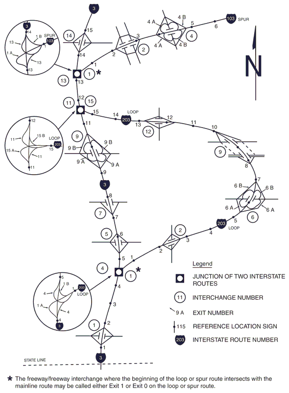
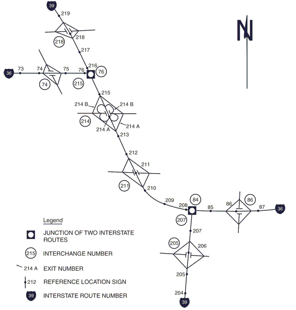
| − | '''Standard.''' Interchange numbering shall be used in signing each freeway interchange exit. Exits are numbered for the interstate system only | + | '''Standard.''' Interchange numbering shall be used in signing each freeway interchange exit. Exits are numbered for the interstate system only and coincide with mileposts. Interchange exit numbers shall be displayed with each Advance Guide sign, Exit Direction sign and Exit Gore sign. The exit number shall be displayed on a separate plaque at the top of the Advance Guide or Exit Direction sign. The exit number plaque shall be 30 in. tall and shall include the word EXIT and the appropriate exit number in a single-line format. Suffix letters shall be used for exit numbering at a multi-exit interchange. The suffix letter shall also be included on the exit number plaque and shall be separated from the exit number by a space having a width of between ½ and ¾ of the height of the suffix letter. Exit numbers shall not include the cardinal initials corresponding to the directions of the cross route. |
Since exits are numbered on the interstate system, the terms NEXT LEFT, NEXT RIGHT, or SECOND LEFT, SECOND RIGHT and NEXT EXIT shall not be used, with the exception of supplemental signs. The exit number shall always be referred to on the exit number panel that is placed above the main guide sign. For interstate guide signs, the term EXIT XX MILES shall not be used. | Since exits are numbered on the interstate system, the terms NEXT LEFT, NEXT RIGHT, or SECOND LEFT, SECOND RIGHT and NEXT EXIT shall not be used, with the exception of supplemental signs. The exit number shall always be referred to on the exit number panel that is placed above the main guide sign. For interstate guide signs, the term EXIT XX MILES shall not be used. | ||
| Line 759: | Line 683: | ||
Interchange exit numbering shall use the reference location sign exit numbering method. The consecutive exit numbering method shall not be used. | Interchange exit numbering shall use the reference location sign exit numbering method. The consecutive exit numbering method shall not be used. | ||
| − | '''Option.''' Exit numbers may also be used with Supplemental Guide signs and Traveler Service signs, after approval of Traffic Division. | + | '''Option.''' Exit numbers may also be used with Supplemental Guide signs and Traveler Service signs, after approval of Central Office Highway Safety and Traffic Division. |
'''Guidance.''' Supplemental guide signs are not to have exit number panels placed above the main sign. | '''Guidance.''' Supplemental guide signs are not to have exit number panels placed above the main sign. | ||
| Line 765: | Line 689: | ||
Exit number plaques should be added to the top right-hand edge of the sign for an exit to the right. | Exit number plaques should be added to the top right-hand edge of the sign for an exit to the right. | ||
| − | '''Standard.''' Because travelers might not expect an exit to the left and might have difficulty in maneuvering to the left, a left exit number plaque shall be added to the top left-hand edge of the sign for all left-hand exits (see Figs. 903.8.24.1 and 903.8.24.2). The word LEFT on the E1-5bP plaque shall be a black legend on a fluorescent yellow rectangular sign panel and shall be centered above the word EXIT. | + | '''Standard.''' Because travelers might not expect an exit to the left and might have difficulty in maneuvering to the left, a left exit number plaque shall be added to the top left-hand edge of the sign for all left-hand exits (see [[#Fig. 903.8.24.1|Figs. 903.8.24.1]] and [[#Fig. 903.8.24.2|903.8.24.2]]). The word LEFT on the E1-5bP plaque shall be a black legend on a fluorescent yellow rectangular sign panel and shall be centered above the word EXIT. |
| − | '''Support.''' The general plan for numbering interchange exits is shown in Figs. 903.8.32.1 through 903.8.32.3. Figs. 903.8.9, 903.8.43 and 903.8.48 through 903.8.53 illustrate the incorporation of exit number plaques on guide signs. | + | '''Support.''' The general plan for numbering interchange exits is shown in Figs. 903.8.32.1 through 903.8.32.3. [[#Fig. 903.8.9|Figs. 903.8.9]], [[#Fig. 903.8.43|903.8.43]] and [[#Fig. 903.8.48|903.8.48]] through [[#Fig. 903.8.53|903.8.53]] illustrate the incorporation of exit number plaques on guide signs. |
[[image:903.8.32.1.jpg|center|thumb|600 px|<center>'''Fig. 903.8.32.1, Example of Interchange Numbering for Mainline and Circumferential Routes'''</center>]] | [[image:903.8.32.1.jpg|center|thumb|600 px|<center>'''Fig. 903.8.32.1, Example of Interchange Numbering for Mainline and Circumferential Routes'''</center>]] | ||
| Line 780: | Line 704: | ||
An example of how to display the distance on a guide sign: the exit panel will show EXIT 23, and the distance in the main guide sign will show ¾ MILE. | An example of how to display the distance on a guide sign: the exit panel will show EXIT 23, and the distance in the main guide sign will show ¾ MILE. | ||
| − | Exit numbers are based on the milepost number in which the crossroad centerline ties to the mainline centerline. For example, if milepost 24 falls before the crossroad centerline and | + | Exit numbers are based on the milepost number in which the crossroad centerline ties to the mainline centerline. For example, if milepost 24 falls before the crossroad centerline and between two exit ramps for a standard cloverleaf, the exits are numbered 24A, 24B. In this example, exit 24A appears before milepost 24. For the opposite direction in this example, the exit numbers are reversed (24B, 24A) in order to have both ramps numbered 24B accessing the same direction on the crossroad. |
| − | '''Standard.''' State maps show the exit numbers for interstates with a different number for each exit. To avoid confusion, separate interchanges are not numbered the same. For example, EXIT 1C is for northbound I-55 exiting to eastbound U.S. Route 199. There should not be another EXIT 1C on southbound I-55, except for an exit to eastbound U.S. Route 199. If this exit does not exist on southbound I-55, there is no EXIT 1C on southbound I-55. When changing existing exit numbers is required, contact | + | '''Standard.''' State maps show the exit numbers for interstates with a different number for each exit. To avoid confusion, separate interchanges are not numbered the same. For example, EXIT 1C is for northbound I-55 exiting to eastbound U.S. Route 199. There should not be another EXIT 1C on southbound I-55, except for an exit to eastbound U.S. Route 199. If this exit does not exist on southbound I-55, there is no EXIT 1C on southbound I-55. When changing existing exit numbers is required, contact Transportation Planning’s, Pavement Analysis and Application Development, in order for the state map to be updated. |
Regardless of whether a mainline route originates within a state or crosses into a state from another state, the southernmost or westernmost terminus shall be the beginning point for interchange numbering. | Regardless of whether a mainline route originates within a state or crosses into a state from another state, the southernmost or westernmost terminus shall be the beginning point for interchange numbering. | ||
| − | Each exit ramp shall have a unique designation. Ramps from opposite directions on the mainline, that take motorists to the same destination, shall have the same exit number. Ramps that serve a movement in one direction, but don’t have a ramp serving traffic from the other direction of travel on the mainline shall have a unique exit number. If more than one exit ramp is located within the same physical mile marker of the mainline and physically exits the mainline separately (i.e. clover leaf interchange), then the exit shall be named with the mile marker number and a supplementary letter. Supplemental | + | Each exit ramp shall have a unique designation. Ramps from opposite directions on the mainline, that take motorists to the same destination, shall have the same exit number. Ramps that serve a movement in one direction, but don’t have a ramp serving traffic from the other direction of travel on the mainline shall have a unique exit number. If more than one exit ramp is located within the same physical mile marker of the mainline and physically exits the mainline separately (i.e. clover leaf interchange), then the exit shall be named with the mile marker number and a supplementary letter. Supplemental letters shall not be used when an exit peels off the mainline and then splits (i.e. directional interchange), unless there is a special circumstance that would require supplemental letters at the interchange. The letters shall begin with “A” and continue in alphabetical order. Any mile of roadway that has an exit with an “A” shall also have at least an exit “B”. Exits shall be supplemented with letters using “A” at the western-most or southern-most exit within a mile marker. The highest letter shall always be used at the eastern-most or northern-most exit within a mile marker. In the event all ramps for the same interchange do not fall within the same mile marker, use the mile marker in which the centerline of the intersecting route falls within. |
For circumferential routes, interchange numbering shall be in a clockwise direction. The numbering shall begin with the first interchange west of the south end of an imaginary north-south line bisecting the circumferential route, at a radial freeway or other interstate route, or some other conspicuous landmark in the circumferential route near a south polar location (see Fig. 903.8.32.1). The interchange numbers on loop routes shall begin at the loop interchange nearest the south or west mainline junction and increase in magnitude toward the north or east mainline junction (see Figure 903.8.32.2). Spur route interchanges shall be numbered in ascending order starting at the interchange where the spur leaves the mainline route (see Fig. 903.8.32.2). | For circumferential routes, interchange numbering shall be in a clockwise direction. The numbering shall begin with the first interchange west of the south end of an imaginary north-south line bisecting the circumferential route, at a radial freeway or other interstate route, or some other conspicuous landmark in the circumferential route near a south polar location (see Fig. 903.8.32.1). The interchange numbers on loop routes shall begin at the loop interchange nearest the south or west mainline junction and increase in magnitude toward the north or east mainline junction (see Figure 903.8.32.2). Spur route interchanges shall be numbered in ascending order starting at the interchange where the spur leaves the mainline route (see Fig. 903.8.32.2). | ||
| Line 812: | Line 736: | ||
===903.8.33.2 Street Names on Guide Signs=== | ===903.8.33.2 Street Names on Guide Signs=== | ||
| − | '''Option.''' The public often | + | '''Option.''' The public often reference MoDOT routes by name instead of the official MoDOT route identification number or letter. If this is the case, the route name may be used in conjunction with the MoDOT route shield. The route shield and, if required, the cardinal direction appear on the first line of copy, and the second line indicates the route name. All route names carry the appropriate designation as street (St), boulevard (Blvd), road (Rd), avenue (Ave), drive (Dr), etc. |
'''Guidance.''' Control cities (see [[#Table 903.8.11 Interstate Sign Control Cities|Table 903.8.11]]) should be used in place of route names when both conditions exist. | '''Guidance.''' Control cities (see [[#Table 903.8.11 Interstate Sign Control Cities|Table 903.8.11]]) should be used in place of route names when both conditions exist. | ||
| Line 820: | Line 744: | ||
===903.8.33.3 Street Identification/Orientation Street Name Signs=== | ===903.8.33.3 Street Identification/Orientation Street Name Signs=== | ||
| − | '''Standard.''' Street Identification/Orientation Street Name signs (D-3c) are used to identify roadways that pass over or under a freeway | + | '''Standard.''' Street Identification/Orientation Street Name signs (D-3c) are used to identify roadways that pass over or under a freeway but have no direct access to the freeway. Street Identification/Orientation Street Name signs (D-3c) have been discontinued. MoDOT shall no longer provide Street Identification/Orientation Street Name signs (D-3c). Existing Street Identification/Orientation Street Name signs (D-3c) shall be left in place until they reach the end of their service life. |
==903.8.34 Advance Guide Signs (MUTCD Section 2E.33)== | ==903.8.34 Advance Guide Signs (MUTCD Section 2E.33)== | ||
| Line 843: | Line 767: | ||
For non-numbered exits to the left, a LEFT plaque (E1-5aP) shall be added to the top left-hand edge of the sign. | For non-numbered exits to the left, a LEFT plaque (E1-5aP) shall be added to the top left-hand edge of the sign. | ||
| − | Advance Guide signs for multi-lane exits having an optional exit lane that also carries the through route and for splits with an option lane shall be Overhead Arrow-per-Lane or diagrammatic signs designed in accordance with EPG 903.8.21 through EPG 903.8.23. | + | Advance Guide signs for multi-lane exits having an optional exit lane that also carries the through route and for splits with an option lane shall be Overhead Arrow-per-Lane or diagrammatic signs designed in accordance with [[#903.8.21 Signing for Option Lanes at Splits and Multi-Lane Exits (MUTCD Section 2E.20)|EPG 903.8.21]] through [[#903.8.23 Design of Freeway and Expressway Diagrammatic Guide Signs for Option Lanes (MUTCD Section 2E.22)|EPG 903.8.23]]. |
| − | Except as provided in EPG 903.8.24, Advance Guide signs, if used, shall contain the distance message. Except as provided in this article, the legend on the Advance Guide signs shall be the same as the legend on the Exit Direction sign, except that the last line shall read EXIT XX MILES. If the interchange has two or more exit roadways, the bottom line shall read EXITS XX MILES. | + | Except as provided in [[#903.8.24 Signing for Interchange Lane Drops (MUTCD Section 2E.24)|EPG 903.8.24]], Advance Guide signs, if used, shall contain the distance message. Except as provided in this article, the legend on the Advance Guide signs shall be the same as the legend on the Exit Direction sign, except that the last line shall read EXIT XX MILES. If the interchange has two or more exit roadways, the bottom line shall read EXITS XX MILES. |
The EXIT ONLY message shall be used to advise drivers of the imminent lane drop situation. The sign shall conform to the provisions of [[#903.8.24 Signing for Interchange Lane Drops (MUTCD Section 2E.24)|EPG 903.8.24]]. | The EXIT ONLY message shall be used to advise drivers of the imminent lane drop situation. The sign shall conform to the provisions of [[#903.8.24 Signing for Interchange Lane Drops (MUTCD Section 2E.24)|EPG 903.8.24]]. | ||
| Line 855: | Line 779: | ||
'''Guidance.''' Where interchange exit numbers are used, the word EXIT(S) should be omitted from the bottom line. | '''Guidance.''' Where interchange exit numbers are used, the word EXIT(S) should be omitted from the bottom line. | ||
| − | '''Option.''' Where the distance between interchanges is more than 1 mile, but less than 2 miles, the first Advance Guide sign may be closer than 2 miles, but not placed | + | '''Option.''' Where the distance between interchanges is more than 1 mile, but less than 2 miles, the first Advance Guide sign may be closer than 2 miles, but not placed to overlap the signing for the previous exit. Duplicate Advance Guide signs or Interchange Sequence Series signs may be placed in the median on the opposite side of the roadway and are not included in the minimum requirements of interchange signing. |
Complex directional interchanges may benefit from a limited number of additional Advance Guide signing. | Complex directional interchanges may benefit from a limited number of additional Advance Guide signing. | ||
| Line 877: | Line 801: | ||
==903.8.36 Other Supplemental Guide Signs (MUTCD Section 2E.35)== | ==903.8.36 Other Supplemental Guide Signs (MUTCD Section 2E.35)== | ||
| − | [[image:E4-1.gif|center|175px|thumb|<center>'''E4- | + | [[image:E4-1.gif|center|175px|thumb|<center>'''E4-3'''</center>]] |
| − | '''Support.''' Supplemental Guide signs can be used to provide information regarding destinations accessible from an interchange, other than places displayed on the standard interchange signing. However, such Supplemental Guide signing can reduce the effectiveness of other more important guide signing because of the possibility of overloading the traveler's capacity to receive visual messages and make appropriate decisions. “The AASHTO Guidelines for the Selection of Supplemental Guide Signs for Traffic Generators Adjacent to Freeways” is incorporated by reference in this section (see Page i for AASHTO’s address). | + | '''Support.''' Supplemental Guide signs can be used to provide information regarding destinations accessible from an interchange, other than places displayed on the standard interchange signing. However, such Supplemental Guide signing can reduce the effectiveness of other more important guide signing because of the possibility of overloading the traveler's capacity to receive visual messages and make appropriate decisions. [https://store.transportation.org/ “The AASHTO Guidelines for the Selection of Supplemental Guide Signs for Traffic Generators Adjacent to Freeways”] is incorporated by reference in this section (see Page i for AASHTO’s address). |
This class of sign includes College and Major Traffic Generator signs. Recreational area and historic signs are white on brown. Major traffic generator signs and most other supplemental signs are white on green. | This class of sign includes College and Major Traffic Generator signs. Recreational area and historic signs are white on brown. Major traffic generator signs and most other supplemental signs are white on green. | ||
| Line 909: | Line 833: | ||
[[image:E11-1.gif|center|175px|thumb|<center>'''E11-1'''</center>]] | [[image:E11-1.gif|center|175px|thumb|<center>'''E11-1'''</center>]] | ||
| − | '''Support.''' MoDOT’s policy on signing for traffic generators is defined in the following rules and regulations. These regulations can be found under the Code of State Regulations Title 7, Division 10, Chapter 17 | + | '''Support.''' MoDOT’s policy on signing for traffic generators is defined in the following rules and regulations. These regulations can be found under the Code of State Regulations Title 7, Division 10, Chapter 17 ([http://www.sos.mo.gov/adrules/csr/current/7csr/7c10-17.pdf 7 CSR 10-17.010]). |
| − | '''Standard.''' | + | '''Standard.''' The Traffic Generator Program, along with other supplemental guide sign programs, is managed by a 3<sup>rd</sup> party contractor. Requests to participate in the Traffic Generator Program shall be forwarded to this 3<sup>rd</sup> party contractor for processing so they may do site reviews, evaluate eligibility and convey options to the perspective participant. |
| − | + | ||
| − | + | '''Support.''' There are select traffic generator style signs which remain MoDOT’s responsibility to install and maintain include: | |
| − | + | :* Signing for Nationally Known / Nationally Prominent Historic Sites (see [[903.9 General Information Signs#903.9.23 Historical Site Signs|EPG 903.9.23]]) | |
| − | + | :* Signing for Lakes over 7,000 acres (see [[#903.8.58 Supplemental Guide Signs for Lakes |EPG 903.8.58]]). | |
| − | |||
| − | |||
| − | |||
| − | |||
| − | |||
| − | |||
| − | |||
| − | |||
| − | |||
| − | |||
| − | |||
| − | |||
| − | |||
| − | |||
| − | |||
| − | |||
| − | |||
| − | |||
| − | |||
| − | |||
| − | |||
| − | |||
| − | |||
| − | |||
| − | |||
| − | |||
| − | |||
| − | |||
| − | |||
| − | |||
| − | |||
| − | |||
| − | |||
| − | |||
| − | |||
| − | |||
| − | |||
| − | |||
| − | |||
| − | |||
| − | |||
| − | |||
| − | |||
| − | |||
| − | |||
| − | |||
| − | |||
| − | |||
| − | |||
| − | |||
| − | |||
| − | |||
| − | |||
| − | |||
| − | |||
| − | |||
| − | : | ||
| − | |||
| − | |||
| − | |||
| − | |||
| − | |||
| − | |||
| − | |||
| − | |||
| − | |||
| − | |||
| − | |||
| − | |||
| − | |||
| − | |||
| − | |||
| − | |||
| − | |||
| − | |||
| − | |||
| − | |||
| − | |||
| − | |||
| − | |||
| − | |||
| − | |||
| − | |||
| − | |||
| − | |||
| − | |||
| − | |||
| − | |||
| − | |||
| − | |||
| − | |||
| − | |||
| − | |||
| − | |||
| − | |||
==903.8.38 Exit Direction Signs (MUTCD Section 2E.36)== | ==903.8.38 Exit Direction Signs (MUTCD Section 2E.36)== | ||
| Line 1,017: | Line 846: | ||
|- | |- | ||
|[[image:E2-1.gif|left|125px|thumb|<center>'''E2-1'''</center>]]||[[image:E2-2.gif|left|125px|thumb|<center>'''E2-2'''</center>]]||[[image:E2-3.gif|left|125px|thumb|<center>'''E2-3'''</center>]]|||[[image:E2-4.gif|left|125px|thumb|<center>'''E2-4'''</center>]] | |[[image:E2-1.gif|left|125px|thumb|<center>'''E2-1'''</center>]]||[[image:E2-2.gif|left|125px|thumb|<center>'''E2-2'''</center>]]||[[image:E2-3.gif|left|125px|thumb|<center>'''E2-3'''</center>]]|||[[image:E2-4.gif|left|125px|thumb|<center>'''E2-4'''</center>]] | ||
| − | | | + | |} |
| + | {| style="margin: 1em auto 1em auto" | ||
|[[image:E2-5.gif|left|125px|thumb|<center>'''E2-5'''</center>]]||[[image:E2-6.gif|left|125px|thumb|<center>'''E2-6'''</center>]]||[[image:E2-7.gif|left|125px|thumb|<center>'''E2-7'''</center>]] | |[[image:E2-5.gif|left|125px|thumb|<center>'''E2-5'''</center>]]||[[image:E2-6.gif|left|125px|thumb|<center>'''E2-6'''</center>]]||[[image:E2-7.gif|left|125px|thumb|<center>'''E2-7'''</center>]] | ||
|} | |} | ||
| Line 1,027: | Line 857: | ||
'''Guidance.''' Post-mounted Exit Direction signs should be installed at the beginning of the deceleration lane. If there is less than 300 ft. from the upstream end of the deceleration lane to the theoretical gore, the Exit Direction sign should be installed overhead over the exiting lane in the vicinity of the theoretical gore. | '''Guidance.''' Post-mounted Exit Direction signs should be installed at the beginning of the deceleration lane. If there is less than 300 ft. from the upstream end of the deceleration lane to the theoretical gore, the Exit Direction sign should be installed overhead over the exiting lane in the vicinity of the theoretical gore. | ||
| − | '''Standard.''' Except where Overhead Arrow-per-Lane guide signs are used, where a through lane is being terminated (dropped) at an exit, the Exit Direction sign shall be placed overhead at the theoretical gore (see Figs. 903.8. | + | '''Standard.''' Except where Overhead Arrow-per-Lane guide signs are used, where a through lane is being terminated (dropped) at an exit, the Exit Direction sign shall be placed overhead at the theoretical gore (see [[#Fig. 903.8.22.1|Figs. 903.8.22.1 through 903.8.22.3]] and [[#Fig. 903.8.24.1|903.8.24.1 through 903.8.24.3]]). |
| − | Except as provided in EPG 903.8.22, where Overhead Arrow-per-Lane guide signs are used for the Advance Guide sign(s) for a multi-lane exit having an optional exit lane that also carries the through route or for a split with an option lane, an Overhead Arrow-per-Lane guide sign shall also be used instead of the Exit Direction sign. This Overhead Arrow-per-Lane guide sign shall include the appropriate exit number plaque (if a numbered exit) and it shall be located near, but not downstream from, the point where the outside edge of the dropped lane begins to diverge from the mainline (see Fig. 903.8.22.1 through 903.8.22.3). | + | Except as provided in [[#903.8.22 Design of Overhead Arrow-per-Lane Guide Signs for Option Lanes (MUTCD Section 2E.21)|EPG 903.8.22]], where Overhead Arrow-per-Lane guide signs are used for the Advance Guide sign(s) for a multi-lane exit having an optional exit lane that also carries the through route or for a split with an option lane, an Overhead Arrow-per-Lane guide sign shall also be used instead of the Exit Direction sign. This Overhead Arrow-per-Lane guide sign shall include the appropriate exit number plaque (if a numbered exit) and it shall be located near, but not downstream from, the point where the outside edge of the dropped lane begins to diverge from the mainline (see [[#Fig. 903.8.22.1|Fig. 903.8.22.1 through 903.8.22.3]]). |
The following provisions shall govern the design and application of overhead Exit Direction signs: | The following provisions shall govern the design and application of overhead Exit Direction signs: | ||
| Line 1,035: | Line 865: | ||
A. The sign shall carry the exit number (if exit numbering is used), the route number, cardinal direction, and destination, as applicable, with a diagonally upward-pointing directional arrow. | A. The sign shall carry the exit number (if exit numbering is used), the route number, cardinal direction, and destination, as applicable, with a diagonally upward-pointing directional arrow. | ||
| − | B. The message EXIT ONLY in black on a fluorescent yellow sign panel shall be used on the overhead Exit Direction sign to advise travelers of a lane drop situation. The sign shall comply with to the provisions of EPG 903.8.24. | + | B. The message EXIT ONLY in black on a fluorescent yellow sign panel shall be used on the overhead Exit Direction sign to advise travelers of a lane drop situation. The sign shall comply with to the provisions of [[#903.8.24 Signing for Interchange Lane Drops (MUTCD Section 2E.24)|EPG 903.8.24]]. |
C. The E1-5P exit number plaque containing the word EXIT shall be used above the exit gore signs on interstates only. | C. The E1-5P exit number plaque containing the word EXIT shall be used above the exit gore signs on interstates only. | ||
| Line 1,045: | Line 875: | ||
For non-numbered exits to the left, a LEFT (E1-5aP) plaque shall be added to the top left-hand edge of the sign. | For non-numbered exits to the left, a LEFT (E1-5aP) plaque shall be added to the top left-hand edge of the sign. | ||
| − | '''Option.''' In some cases, principally in urban areas, where restricted sight distance because of structures or unusual alignment make it impossible to locate the Exit Direction sign without violating the required minimum spacing (see EPG 903.8.34) between major guide signs, Interchange Sequence signs (see EPG 903.8.43) may be substituted for an Advance Guide sign. | + | '''Option.''' In some cases, principally in urban areas, where restricted sight distance because of structures or unusual alignment make it impossible to locate the Exit Direction sign without violating the required minimum spacing (see [[#903.8.34 Advance Guide Signs (MUTCD Section 2E.33)|EPG 903.8.34]]) between major guide signs, Interchange Sequence signs (see [[#903.8.43 Interchange Sequence Signs (MUTCD Section 2E.40)|EPG 903.8.43]]) may be substituted for an Advance Guide sign. |
'''Guidance.''' At multi-exit interchanges, the Exit Direction sign should be located directly over the exiting lane for the first exit. At the same location, and normally over the right-hand through lane, an Advance Guide sign for the second exit should be located. Only for those conditions where the through movement is not evident is a confirmatory message (Pull-through sign) to be used over the left lane(s) to guide travelers traveling through an interchange. In the interest of sign spreading, three signs on one structure are not to be used. When the freeway or expressway is on an overpass, the Exit Direction sign should be installed on an overhead support over the exit lane in advance of the gore point. | '''Guidance.''' At multi-exit interchanges, the Exit Direction sign should be located directly over the exiting lane for the first exit. At the same location, and normally over the right-hand through lane, an Advance Guide sign for the second exit should be located. Only for those conditions where the through movement is not evident is a confirmatory message (Pull-through sign) to be used over the left lane(s) to guide travelers traveling through an interchange. In the interest of sign spreading, three signs on one structure are not to be used. When the freeway or expressway is on an overpass, the Exit Direction sign should be installed on an overhead support over the exit lane in advance of the gore point. | ||
| Line 1,063: | Line 893: | ||
'''Support.''' The Exit Gore (E5 series) sign in the gore indicates the exiting point or the place of departure from the main roadway. Consistent application of this sign at each exit is important. | '''Support.''' The Exit Gore (E5 series) sign in the gore indicates the exiting point or the place of departure from the main roadway. Consistent application of this sign at each exit is important. | ||
| − | '''Standard.''' The gore shall be defined as the area located between the main roadway and the ramp just beyond where the ramp branches from the main roadway. The Exit Gore sign shall be located in the gore and shall carry the word EXIT and an appropriate upward slanting arrow. If suffix letters are used for exit numbering at multi-exit interchange, the suffix letter shall also be included on the Exit Gore sign and shall be separated from the exit number by a space having a width of between 1/2 and 3/4 the height of the suffix letter. Breakaway or yielding supports shall be used. | + | '''Standard.''' The gore shall be defined as the area located between the main roadway and the ramp just beyond where the ramp branches from the main roadway. The Exit Gore sign shall be located in the gore and shall carry the word EXIT and an appropriate upward slanting arrow. If suffix letters are used for exit numbering at a multi-exit interchange, the suffix letter shall also be included on the Exit Gore sign and shall be separated from the exit number by a space having a width of between 1/2 and 3/4 the height of the suffix letter. Breakaway or yielding supports shall be used. |
The exit numbers shall be incorporated into the sign legend on interstate routes only. | The exit numbers shall be incorporated into the sign legend on interstate routes only. | ||
| Line 1,073: | Line 903: | ||
To improve the visibility of the gore for exiting drivers, a Type 1 Object Marker may be installed on each sign support below the Exit Gore sign. | To improve the visibility of the gore for exiting drivers, a Type 1 Object Marker may be installed on each sign support below the Exit Gore sign. | ||
| − | '''Standard.''' An Exit Gore sign shall be used when the replacement of an existing assembly of an E5-1 sign and an E5-1bP plaque becomes necessary. | + | '''Standard.''' An Exit Gore (E5-1a) sign shall be used when the replacement of an existing assembly of an E5-1 sign and an E5-1bP plaque becomes necessary. |
==903.8.40 Post-Interchange Signs (MUTCD Section 2E.38)== | ==903.8.40 Post-Interchange Signs (MUTCD Section 2E.38)== | ||
| Line 1,136: | Line 966: | ||
'''Guidance.''' The verbiage on the Interchange Sequence sign should appear on the appropriate advance and exit guide signs for sign continuity. | '''Guidance.''' The verbiage on the Interchange Sequence sign should appear on the appropriate advance and exit guide signs for sign continuity. | ||
| − | Interchange Sequence signs should be located in the median or placed on a bridge whenever possible. After the first of the series, Interchange Sequence signs should be placed approximately midway between interchanges. This will | + | Interchange Sequence signs should be located in the median or placed on a bridge whenever possible. After the first of the series, Interchange Sequence signs should be placed approximately midway between interchanges. This will allow two signs (one for each direction of traffic) to be placed back to back on the same truss. Since the signs are usually back-to-back, a butterfly truss should be installed in the median of divided highways. Barrier protection should be used according to [[:Category:617 Traffic Barrier|EPG 617 Traffic Barrier]]. |
'''Standard.''' Interchange Sequence signs located in the median shall be installed at overhead sign height. | '''Standard.''' Interchange Sequence signs located in the median shall be installed at overhead sign height. | ||
| Line 1,143: | Line 973: | ||
'''Support.''' An example of how to use a common street name: Route 67 is commonly referred to as Lindbergh Boulevard. On the advance and exit guide signs, a U.S. Route 67 shield appears with the common name “Lindbergh Boulevard” underneath. The interchange sequence signs show Lindbergh Blvd and/or shield. | '''Support.''' An example of how to use a common street name: Route 67 is commonly referred to as Lindbergh Boulevard. On the advance and exit guide signs, a U.S. Route 67 shield appears with the common name “Lindbergh Boulevard” underneath. The interchange sequence signs show Lindbergh Blvd and/or shield. | ||
| − | + | <div id="Fig. 903.8.43"></div> | |
[[image:903.8.43.jpg|thumb|center|600px|<center>'''Fig. 903.8.43, Example of Using an Interchange Sequence Sign for Closely-Spaced Interchanges'''</center>]] | [[image:903.8.43.jpg|thumb|center|600px|<center>'''Fig. 903.8.43, Example of Using an Interchange Sequence Sign for Closely-Spaced Interchanges'''</center>]] | ||
| Line 1,166: | Line 996: | ||
'''Support.''' Many freeways or expressways pass through historical or recreational regions, or urban areas served by a succession of three or more interchanges. | '''Support.''' Many freeways or expressways pass through historical or recreational regions, or urban areas served by a succession of three or more interchanges. | ||
| − | '''Option.''' Such regions or areas may be indicated by a NEXT XX EXITS (E4- | + | '''Option.''' Such regions or areas may be indicated by a NEXT XX EXITS (E4-1) sign located in advance of the Advance Guide sign or signs for the first interchange. The sign legend should identify the region or area followed by the words NEXT XX EXITS. |
==903.8.46 Overhead Intersection Ramp Guide Sign== | ==903.8.46 Overhead Intersection Ramp Guide Sign== | ||
| Line 1,188: | Line 1,018: | ||
'''Support.''' Freeway-to-freeway interchanges are major decision points where the effect of taking a wrong ramp cannot be easily corrected. Reversing direction on the connecting freeway or reentering to continue on the intended course is usually not possible. Figs 903.8.48.1 and 903.8.48.2 show examples of guide signs at a freeway-to-freeway interchange. | '''Support.''' Freeway-to-freeway interchanges are major decision points where the effect of taking a wrong ramp cannot be easily corrected. Reversing direction on the connecting freeway or reentering to continue on the intended course is usually not possible. Figs 903.8.48.1 and 903.8.48.2 show examples of guide signs at a freeway-to-freeway interchange. | ||
| − | '''Guidance.''' The sign messages should contain only the route shield, cardinal direction and the name of the next control city on the route. Arrows should point as indicated in [[903.7 Conventional Road Guide Signs#903.7.8 Arrows (MUTCD Section 2D.08)|EPG 903.7.8]], except where Overhead Arrow-per-Lane | + | '''Guidance.''' The sign messages should contain only the route shield, cardinal direction and the name of the next control city on the route. Arrows should point as indicated in [[903.7 Conventional Road Guide Signs#903.7.8 Arrows (MUTCD Section 2D.08)|EPG 903.7.8]], except where Overhead Arrow-per-Lane signs are used in accordance with [[#903.8.21 Signing for Option Lanes at Splits and Multi-Lane Exits (MUTCD Section 2E.20)|EPG 903.8.21]] through [[#903.8.23 Design of Freeway and Expressway Diagrammatic Guide Signs for Option Lanes (MUTCD Section 2E.22)|EPG 903.8.23]]. |
'''Support.''' At splits where the off-route movement is to the left or where there is an optional lane split, expectancy problems usually result. | '''Support.''' At splits where the off-route movement is to the left or where there is an optional lane split, expectancy problems usually result. | ||
| Line 1,194: | Line 1,024: | ||
'''Standard.''' At splits where the off-route movement is to the left, the Left Exit Number plaque shall be added at the top left-hand edge of the guide sign. Overhead Arrow-per-Lane or Diagrammatic guide signs shall be used for freeways splits with an option lane and for multi-lane freeway-to-freeway exits having an option lane. | '''Standard.''' At splits where the off-route movement is to the left, the Left Exit Number plaque shall be added at the top left-hand edge of the guide sign. Overhead Arrow-per-Lane or Diagrammatic guide signs shall be used for freeways splits with an option lane and for multi-lane freeway-to-freeway exits having an option lane. | ||
| − | Overhead signs shall be used at a distance of 1 mile and at the theoretical gore of each connecting ramp. When Overhead Arrow-per-Lane | + | Overhead signs shall be used at a distance of 1 mile and at the theoretical gore of each connecting ramp. When Overhead Arrow-per-Lane guide signs are used, they shall comply with [[#903.8.22 Design of Overhead Arrow-per-Lane Guide Signs for Option Lanes (MUTCD Section 2E.21)|EPG 903.8.22]] and [[#903.8.23 Design of Freeway and Expressway Diagrammatic Guide Signs for Option Lanes (MUTCD Section 2E.22)|EPG 903.8.23]]. |
'''Option.''' Overhead signs may also be used at the ½-mile and 2-mile locations. | '''Option.''' Overhead signs may also be used at the ½-mile and 2-mile locations. | ||
| Line 1,203: | Line 1,033: | ||
Where extra emphasis of an especially low advisory ramp speed is needed, an EXIT XX MPH sign panel may be placed at the bottom of the Exit Direction sign to supplement, but not to replace, the exit or ramp advisory speed warning signs. | Where extra emphasis of an especially low advisory ramp speed is needed, an EXIT XX MPH sign panel may be placed at the bottom of the Exit Direction sign to supplement, but not to replace, the exit or ramp advisory speed warning signs. | ||
| − | + | <div id="Fig. 903.8.48"></div> | |
[[image:903.8.48.1.jpg|center|600px|thumb|'''<center>Fig. 903.8.48.1, Example of Guide Signs for a Freeway-to-Freeway Interchange showing Signing for a Two-Lane Exit Ramp with Two Dropped Lanes and a Bifurcation Beyond the Mainline Gore'''</center>]] | [[image:903.8.48.1.jpg|center|600px|thumb|'''<center>Fig. 903.8.48.1, Example of Guide Signs for a Freeway-to-Freeway Interchange showing Signing for a Two-Lane Exit Ramp with Two Dropped Lanes and a Bifurcation Beyond the Mainline Gore'''</center>]] | ||
| Line 1,214: | Line 1,044: | ||
'''Guidance.''' The Advance Guide signs should include two place names, one corresponding to each exit ramp, with the name of the place served by the first exit on the upper line. | '''Guidance.''' The Advance Guide signs should include two place names, one corresponding to each exit ramp, with the name of the place served by the first exit on the upper line. | ||
| − | '''Standard.''' An Overhead Guide sign shall be placed at the theoretical gore of the first exit ramp, with a diagonally upward-pointing directional arrow on the exit direction sign for that exit and the message XX MILE, or EXIT XX MILES if interchange numbering is not used, on the Advance Guide sign for the second exit, as shown in Fig. 903.8.49. The second exit shall be indicated by an overhead Exit Direction sign over the auxiliary lane. An Exit Gore sign shall also be used at each gore (see EPG 903.8.39). | + | '''Standard.''' An Overhead Guide sign shall be placed at the theoretical gore of the first exit ramp, with a diagonally upward-pointing directional arrow on the exit direction sign for that exit and the message XX MILE, or EXIT XX MILES if interchange numbering is not used, on the Advance Guide sign for the second exit, as shown in Fig. 903.8.49. The second exit shall be indicated by an overhead Exit Direction sign over the auxiliary lane. An Exit Gore sign shall also be used at each gore (see [[#https://mutcd.fhwa.dot.gov/|EPG 903.8.39]]). |
| − | Interchanges with more than one exit from the main line shall be numbered as described in | + | Interchanges with more than one exit from the main line shall be numbered as described in [[#903.8.32 Interchange Exit Numbering (MUTCD Section 2E.31)|EPG 903.8.32]] with an appropriate suffix. |
| − | |||
| − | |||
'''Guidance.''' Where the mainline passes under the crossroad and the exit roadway is located beyond the overcrossing structure, the overhead Exit Direction sign for the second exit should be placed either on the overcrossing structure or on a separate structure located immediately in front of the overcrossing structure. | '''Guidance.''' Where the mainline passes under the crossroad and the exit roadway is located beyond the overcrossing structure, the overhead Exit Direction sign for the second exit should be placed either on the overcrossing structure or on a separate structure located immediately in front of the overcrossing structure. | ||
| Line 1,238: | Line 1,066: | ||
==903.8.51 Partial Cloverleaf Interchange (MUTCD Section 2E.47)== | ==903.8.51 Partial Cloverleaf Interchange (MUTCD Section 2E.47)== | ||
| − | '''Support.''' Examples of guide signs for partial cloverleaf interchanges are shown in | + | '''Support.''' Examples of guide signs for partial cloverleaf interchanges are shown in Fig. 903.8.51. |
'''Guidance.''' Where the mainline passes under the crossroad and the exit roadway is located beyond the overcrossing structure, the overhead Exit Direction sign should be placed either on the overcrossing structure or on a separate structure located immediately in front of the overcrossing structure. | '''Guidance.''' Where the mainline passes under the crossroad and the exit roadway is located beyond the overcrossing structure, the overhead Exit Direction sign should be placed either on the overcrossing structure or on a separate structure located immediately in front of the overcrossing structure. | ||
| Line 1,250: | Line 1,078: | ||
==903.8.52 Diamond Interchange (MUTCD Section 2E.48)== | ==903.8.52 Diamond Interchange (MUTCD Section 2E.48)== | ||
| − | '''Support.''' Examples of guide signs for diamond interchanges are shown in Fig. 903.8.52 and [[903. | + | '''Support.''' Examples of guide signs for diamond interchanges are shown in Fig. 903.8.52 and [[903.20 Signing for Rail and Light Rail Transit Grade Crossings|EPG 903.20 Signing for Rail and Light Rail Transit Grade Crossings]]. |
'''Standard.''' For numbered exits, the singular message EXIT shall be used on the Exit Number plaques with Advance Guide and Exit Direction signs. For non-numbered exits, the singular message EXIT shall be used as part of the distance message on the Advance Guide signs. | '''Standard.''' For numbered exits, the singular message EXIT shall be used on the Exit Number plaques with Advance Guide and Exit Direction signs. For non-numbered exits, the singular message EXIT shall be used as part of the distance message on the Advance Guide signs. | ||
| Line 1,256: | Line 1,084: | ||
'''Support.''' The typical diamond interchange ramp departs from the mainline roadway so that a speed reduction generally is not necessary to permit a driver to negotiate an exit maneuver from the mainline onto the ramp roadway. | '''Support.''' The typical diamond interchange ramp departs from the mainline roadway so that a speed reduction generally is not necessary to permit a driver to negotiate an exit maneuver from the mainline onto the ramp roadway. | ||
| − | '''Guidance.''' | + | '''Guidance.''' When a speed reduction is not necessary, an exit speed sign should not be used. |
'''Option.''' An Advisory Exit Speed sign may be used where an engineering study shows that it is necessary to display a speed reduction message for ramp signing (see [[903.6 Warning Signs#903.6.36 Advisory Exit and Ramp Speed Signs (W13-2 and W13-3) (MUTCD Section 2C.14)|EPG 903.6.36]]). | '''Option.''' An Advisory Exit Speed sign may be used where an engineering study shows that it is necessary to display a speed reduction message for ramp signing (see [[903.6 Warning Signs#903.6.36 Advisory Exit and Ramp Speed Signs (W13-2 and W13-3) (MUTCD Section 2C.14)|EPG 903.6.36]]). | ||
| Line 1,270: | Line 1,098: | ||
==903.8.53 Diamond Interchange in Urban Area (MUTCD Section 2E.49)== | ==903.8.53 Diamond Interchange in Urban Area (MUTCD Section 2E.49)== | ||
| − | '''Support.''' Examples of guide signs for diamond interchanges in an urban area are shown in Fig. 903.8.53 and [[903. | + | '''Support.''' Examples of guide signs for diamond interchanges in an urban area are shown in Fig. 903.8.53 and [[903.20 Signing for Rail and Light Rail Transit Grade Crossings|EPG 903.20 Signing for Rail and Light Rail Transit Grade Crossings]]. This example includes the use of the Community Interchanges Identification sign (see [[#903.8.44 Community Interchanges Identification Signs (MUTCD Section 2E.41)|EPG 903.8.44]]) that might be useful if two or more interchanges serve the same community. |
In urban areas, street names are often displayed as the principal message in destination signs. | In urban areas, street names are often displayed as the principal message in destination signs. | ||
'''Option.''' If interchanges are too closely spaced to properly locate the Advance Guide signs, they may be placed closer to the exit with the distances displayed adjusted accordingly. | '''Option.''' If interchanges are too closely spaced to properly locate the Advance Guide signs, they may be placed closer to the exit with the distances displayed adjusted accordingly. | ||
| − | + | <div id="Fig. 903.8.53"></div> | |
[[image:903.8.53.jpg|center|600px|thumb|'''<center>Fig. 903.8.53, Example of Guide Signs for a Diamond Interchange in an Urban Area'''</center>]] | [[image:903.8.53.jpg|center|600px|thumb|'''<center>Fig. 903.8.53, Example of Guide Signs for a Diamond Interchange in an Urban Area'''</center>]] | ||
==903.8.54 Closely Spaced Interchanges (MUTCD Section 2E.50)== | ==903.8.54 Closely Spaced Interchanges (MUTCD Section 2E.50)== | ||
| − | '''Support.''' EPG 903.8.9 contains information regarding sign spreading where the Exit Direction sign and the Advance Guide sign for the next interchange are mounted overhead. Sign spreading is particularly beneficial where interchanges are closely spaced and overhead signing is used in conjunction with Interchange Sequence signs as provided in this article. | + | '''Support.''' [[#903.8.9 Number of Signs at an Overhead Installation and Sign Spreading (MUTCD Section 2E.10)|EPG 903.8.9]] contains information regarding sign spreading where the Exit Direction sign and the Advance Guide sign for the next interchange are mounted overhead. Sign spreading is particularly beneficial where interchanges are closely spaced and overhead signing is used in conjunction with Interchange Sequence signs as provided in this article. |
| − | '''Guidance.''' Interchange Sequence signs should be used at closely spaced interchanges. When used, they identify and show street names and distances for the next two or three exits as shown in Fig. 903.8.43. | + | '''Guidance.''' Interchange Sequence signs should be used at closely spaced interchanges. When used, they identify and show street names and distances for the next two or three exits as shown in [[#Fig. 903.8.43|Fig. 903.8.43]]. |
'''Standard.''' Advance Guide signs for closely spaced interchanges shall show information for only one interchange. | '''Standard.''' Advance Guide signs for closely spaced interchanges shall show information for only one interchange. | ||
| Line 1,294: | Line 1,122: | ||
'''Support.''' Because there are a number of different ramp configurations that are commonly used at interchanges with conventional roads, drivers on the conventional road cannot reliably predict whether they will be required to turn left or right in order to enter the correct ramp to access the freeway or expressway in the desired direction of travel. Consistently applied signing for conventional road approaches to freeway or expressway interchanges is highly desirable. | '''Support.''' Because there are a number of different ramp configurations that are commonly used at interchanges with conventional roads, drivers on the conventional road cannot reliably predict whether they will be required to turn left or right in order to enter the correct ramp to access the freeway or expressway in the desired direction of travel. Consistently applied signing for conventional road approaches to freeway or expressway interchanges is highly desirable. | ||
| − | '''Guidance.''' The signing of conventional roads approaching an interchange should consist of a sequence containing the following signs (see [[903. | + | '''Guidance.''' The signing of conventional roads approaching an interchange should consist of a sequence containing the following signs (see [[903.20 Signing for Rail and Light Rail Transit Grade Crossings|EPG 903.20 Signing for Rail and Light Rail Transit Grade Crossings]]): |
| − | A. Junction Assembly | + | :A. Junction Assembly |
| − | B. Destination sign | + | :B. Destination sign |
| − | C. Directional Assembly for the first ramp | + | :C. Directional Assembly for the first ramp |
| − | D. Advance Route Turn Assembly | + | :D. Advance Route Turn Assembly |
| − | E. Directional Assembly or Crossroad Guide sign for the second ramp | + | :E. Directional Assembly or Crossroad Guide sign for the second ramp |
'''Standard.''' If used, the Crossroad Guide (see [[903.8 Freeway and Expressway Guide Signs#903.8.41 Crossroad Guide Sign|EPG 903.8.41]]) sign shall consist of a white legend and border on a green background. It shall contain the freeway or expressway route shield(s), cardinal direction, and directional arrow(s). | '''Standard.''' If used, the Crossroad Guide (see [[903.8 Freeway and Expressway Guide Signs#903.8.41 Crossroad Guide Sign|EPG 903.8.41]]) sign shall consist of a white legend and border on a green background. It shall contain the freeway or expressway route shield(s), cardinal direction, and directional arrow(s). | ||
| Line 1,359: | Line 1,187: | ||
No pictograph shall be displayed on the signs. | No pictograph shall be displayed on the signs. | ||
| + | |||
[[Category:903 Highway Signing|903.08]] | [[Category:903 Highway Signing|903.08]] | ||
Latest revision as of 08:25, 22 June 2021
Contents
- 1 903.8.1 Scope of Freeway and Expressway Guide Sign Standards (MUTCD Section 2E.01)
- 2 903.8.2 Freeway and Expressway Signing Principles (MUTCD Section 2E.02)
- 3 903.8.3 General Design (MUTCD Section 2E.04)
- 4 903.8.4 Guide Sign Colors (MUTCD Section 2E.05)
- 5 903.8.5 Retroreflection or Illumination (MUTCD Section 2E.06)
- 6 903.8.6 Urban Signing Characteristics (MUTCD Section 2E.06)
- 7 903.8.7 Rural Signing Characteristics (MUTCD Section 2E.08)
- 8 903.8.9 Number of Signs at an Overhead Installation and Sign Spreading (MUTCD Section 2E.10)
- 9 903.8.10 Route Confirmation/Pull-Through Signs (MUTCD Section 2E.12)
- 10 903.8.11 Designation of Destinations (MUTCD Section 2E.13)
- 11 903.8.12 Size and Style of Letters and Signs (MUTCD Section 2E.14)
- 12 903.8.13 Line Spacing (MUTCD Section 2E.15)
- 13 903.8.14 Sign Borders (MUTCD Section 2E.16)
- 14 903.8.15 Abbreviations (MUTCD Section 2E.17)
- 15 903.8.16 Punctuation
- 16 903.8.17 Symbols (MUTCD Section 2E.18)
- 17 903.8.18 Arrows for Interchange Guide Signs (MUTCD Section 2E.19)
- 18 903.8.19 Cardinal Directions
- 19 903.8.20 Sign Size Management
- 20 903.8.21 Signing for Option Lanes at Splits and Multi-Lane Exits (MUTCD Section 2E.20)
- 21 903.8.22 Design of Overhead Arrow-per-Lane Guide Signs for Option Lanes (MUTCD Section 2E.21)
- 22 903.8.23 Design of Freeway and Expressway Diagrammatic Guide Signs for Option Lanes (MUTCD Section 2E.22)
- 23 903.8.24 Signing for Interchange Lane Drops (MUTCD Section 2E.24)
- 24 903.8.25 Lane Reduction and Route Termination
- 25 903.8.26 Overhead Sign Installations (MUTCD Section 2E.25)
- 26 903.8.27 Lateral Offset (MUTCD Section 2E.26)
- 27 903.8.28 Guide Sign Classification (MUTCD Section 2E.03)
- 28 903.8.29 Route Signs and Trailblazer Assemblies (MUTCD Section 2E.27)
- 29 903.8.30 Signs for Intersections At Grade (MUTCD Section 2E.29)
- 30 903.8.31 Interchange Guide Signs (MUTCD Section 2E.30)
- 31 903.8.32 Interchange Exit Numbering (MUTCD Section 2E.31)
- 32 903.8.33 Interchange Classification (MUTCD Section 2E.32)
- 33 903.8.34 Advance Guide Signs (MUTCD Section 2E.33)
- 34 903.8.35 Next Exit Plaques (MUTCD Section 2E.34)
- 35 903.8.36 Other Supplemental Guide Signs (MUTCD Section 2E.35)
- 36 903.8.37 Traffic Generator Signing
- 37 903.8.38 Exit Direction Signs (MUTCD Section 2E.36)
- 38 903.8.39 Exit Gore Signs (E5-1 Series) (MUTCD Section 2E.37)
- 39 903.8.40 Post-Interchange Signs (MUTCD Section 2E.38)
- 40 903.8.41 Crossroad Guide Sign
- 41 903.8.42 Post-Interchange Distance Signs (MUTCD Section 2E.39)
- 42 903.8.43 Interchange Sequence Signs (MUTCD Section 2E.40)
- 43 903.8.44 Community Interchanges Identification Signs (MUTCD Section 2E.41)
- 44 903.8.45 NEXT XX EXITS Sign (MUTCD Section 2E.42)
- 45 903.8.46 Overhead Intersection Ramp Guide Sign
- 46 903.8.47 Signing by Type of Interchange (MUTCD Section 2E.43)
- 47 903.8.48 Freeway-to-Freeway Interchange (MUTCD Section 2E.44)
- 48 903.8.49 Cloverleaf Interchange (MUTCD Section 2E.45)
- 49 903.8.50 Cloverleaf Interchange with Collector-Distributor Roadways (MUTCD Section 2E.46)
- 50 903.8.51 Partial Cloverleaf Interchange (MUTCD Section 2E.47)
- 51 903.8.52 Diamond Interchange (MUTCD Section 2E.48)
- 52 903.8.53 Diamond Interchange in Urban Area (MUTCD Section 2E.49)
- 53 903.8.54 Closely Spaced Interchanges (MUTCD Section 2E.50)
- 54 903.8.55 Minor Interchange (MUTCD Section 2E.51)
- 55 903.8.56 Signing of Approaches and Connecting Roadways (MUTCD Section 2E.52)
- 56 903.8.57 Weigh Station Signing (MUTCD Section 2E.54)
- 57 903.8.58 Supplemental Guide Signs for Lakes
903.8.1 Scope of Freeway and Expressway Guide Sign Standards (MUTCD Section 2E.01)
Support. This article provides a uniform and effective system of signing for high-volume, high-speed motor vehicle traffic on freeways and expressways. The requirements and specifications for expressway signing exceed those for conventional roads (see EPG 903.7), but are less than those for freeway signing. Since there are many geometric design variables to be found in existing roads, a signing concept commensurate with prevailing conditions is the primary consideration. Refer to EPG 900.1.13 Definitions of Headings, Words and Phrases for definitions of freeway and expressway.
Guide signs for freeways and expressways are primarily identified by the name of the sign rather than by an assigned sign designation.
Standard. The provisions of this article shall apply to any highway that meets the definition of freeway or expressway facilities.
903.8.2 Freeway and Expressway Signing Principles (MUTCD Section 2E.02)
Support. The development of a signing system for freeways and expressways is approached on the premise that the signing is primarily for the benefit and direction of travelers who are not familiar with the route or area. The signing furnishes travelers with clear instructions for orderly progress to their destinations. Sign installations are an integral part of the facility and, as such, are best planned concurrently with the development of highway location and geometric design. For optimal results, plans for signing are analyzed during the earliest stages of preliminary design and details are correlated as final design is developed. The excessive signing found on many major highways usually is the result of using a multitude of signs that are too small, poorly designed and placed to accomplish the intended purpose.
Freeway and expressway signing should be considered and developed as a planned system of installations. An engineering study is sometimes necessary for proper solution of the problems of many individual locations, but, in addition, consideration of an entire route is necessary.
Guidance. Travelers should be guided with consistent signing on the approaches to interchanges when they drive from one state to another and when driving through rural or urban areas. Because geographical, geometric and operating factors regularly create significant differences between urban and rural conditions, the signing should take these conditions into account. Guide signs on freeways and expressways should serve distinct functions as follows:
- A. Give directions to destinations, or to streets or highway routes, at intersections or interchanges;
- B. Furnish advance notice of the approach to intersections or interchanges;
- C. Direct travelers into appropriate lanes in advance of diverging or merging movements;
- D. Identify routes and directions on those routes;
- E. Show distances to destinations;
- F. Indicate access to general motorist services, rest, scenic and recreational areas; and
- G. Provide other information of value to the traveler.
903.8.3 General Design (MUTCD Section 2E.04)
Support. Signs are designed so that they are legible to travelers approaching them and readable in time to permit proper responses. Desired design characteristics include: (a) long visibility distances, (b) large lettering, symbols and arrows, and (c) short legends for quick comprehension.
Standard. Standard shapes and colors shall be used so that travelers can promptly recognize traffic signs.
Support. Guide signs are generally considered to be the white-on-green signs and are normally associated with major highways and interstates. When preparing signing plans, consistency and coordination with existing signing is critical. This does not mean poor signing should be replaced in kind for the sake of consistency. Consistent application of legend styles, abbreviations, control cities, wording, and arrow placement are important for proper driver guidance and expectancy. This is accomplished by routinely applying standards. Signing is basically for the first-time driver, not repeat traffic. An example of poor signing would be having two advance guide signs for the same exit listing different control cities. Another example would be using local cities for general guidance instead of standard control cities. It is important to have consistent signing throughout the state of Missouri.
Guide sign standards in this section and as shown on the standard plans are used whenever possible. Conditions that require deviation from these standards are held to a minimum and justified. Design variances require district justification at the preliminary sign location stage. Signing variances are also noted in the plans. Some deviations from design standards may require approval as outlined in EPG 131.1 Design Exception Process.
903.8.4 Guide Sign Colors (MUTCD Section 2E.05)
Standard. Guide signs on freeways and expressways, except as otherwise provided in this article, shall have white letters, symbols, arrows, and borders on a green background.
Support. In the case of “EXIT ONLY” panels or other legends that require extra emphasis, the legend shall be black on fluorescent yellow background.
Color requirements for route signs and trailblazers, signs with blank-out or changeable messages, signs for services, rest areas, park and recreational areas and for certain miscellaneous signs are provided in the individual sections dealing with the particular sign or sign group.
903.8.5 Retroreflection or Illumination (MUTCD Section 2E.06)
Standard. Letters, numerals, symbols, arrows, and borders of all guide signs shall be retroreflectorized. The background of all guide signs that are not independently illuminated shall be retroreflective.
Support. Where there is no serious interference from extraneous light sources, retroreflectorized post-mounted signs usually provide adequate nighttime visibility.
On freeways and expressways where much driving at night is done with low-beam headlights, the amount of headlight illumination incident to an overhead sign display is relatively small.
Option. Overhead sign lighting may be installed based on engineering judgement. Typical installations are limited to signs located in tunnels or under structures.
Support. There are two types of reflective sheeting used by MoDOT, (see Standard Plans 903):
- 1) ASTM Type IV Prismatic
- 2) ASTM Type IX or XI Prismatic
903.8.6 Urban Signing Characteristics (MUTCD Section 2E.06)
Support. Urban conditions are characterized not so much by city limits or other arbitrary boundaries, as by the following features:
- A. Mainline roadways with more than two lanes in each direction;
- B. High traffic volumes on the through roadways;
- C. High volumes of traffic entering and leaving interchanges;
- D. Interchanges closely spaced;
- E. Roadway and interchange lighting;
- F. Three or more interchanges serving the major city;
- G. A loop, circumferential or spur serving a sizable portion of the urban population; and
- H. Visual clutter from roadside development.
Operating conditions and road geometrics on urban freeways and expressways usually make special sign treatments desirable, including:
- A. Use of Interchange Sequence signs;
- B. Use of sign spreading to the maximum extent possible (see [[#903.8.11 Designation of Destinations (MUTCD Section 2E.13)|EPG 903.8.11);
- C. Elimination of General or Specific Service signing (see EPG 903.10 General Service Signs);
- D. Reduction to a minimum of post-interchange signs (see EPG 903.8.40 Post-Interchange Signs);
- E. Display of advance signs at distances closer to the interchange, with appropriate adjustments in the legend (see EPG 903.8.34 Advance Guide Signs);
- F. Use of overhead signs on roadway structures and independent sign supports (see Overhead Sign Installations);
- G. Use of Overhead Arrow-per-Lane guide signs in advance of intersections and interchanges; and
- H. Frequent use of street names as the principal message in guide signs.
Lower speeds that are often characteristic of urban operations do not justify lower signing standards. Typical traffic patterns are more complex for the traveler to negotiate and large, easy-to-read legends are, therefore, just as necessary as on rural highways.
903.8.7 Rural Signing Characteristics (MUTCD Section 2E.08)
Support. Rural areas ordinarily have greater distances between interchanges that permit adequate spacing for the sequences of signs on the approach to and departure from each interchange. However, the absence of traffic in adjoining lanes and on entering or exiting ramps often adds monotony or inattention to rural driving. This increases the importance of signs that call for decisions or actions.
Guidance. Where there are long distances between interchanges and the alignment is relatively unchanging, signs should be positioned for their best effect on travelers. The tendency to group all signing in the immediate vicinity of rural interchanges should be avoided by considering the entire route in the development of signing plans. Extra effort should be given to the placement of signs at natural target locations to command the attention of the traveler, particularly when the message requires an action by the traveler.
903.8.9 Number of Signs at an Overhead Installation and Sign Spreading (MUTCD Section 2E.10)
Guidance. If overhead signs are warranted, as set forth in Overhead Sign Installation, the number of signs at these locations should be limited to only those essential in communicating pertinent destination information to the traveler. Exit Direction signs for a single exit and the Advance Guide signs should have only one sign with one or two destinations. Regulatory signs, such as speed limits, are not to be used in conjunction with overhead guide sign installations. Because travelers have limited time to read and comprehend sign messages, there is not to be more than three guide signs displayed at any one location either on the overhead structure or its support.
Option. At overhead locations, more than one sign may be installed to advise of a multiple exit condition at an interchange. If the roadway ramp or crossing roadway has complex or unusual geometrics, additional signs with confirming messages may be provided to properly guide the traveler.
Support. Sign spreading, illustrated by Figure 903.8.9, is where major overhead signs are spaced so that travelers are not overloaded with a group of signs at a single location
Guidance. Where overhead signing is used, sign spreading should be used at all single exit interchanges and to the extent possible at multi-exit interchanges. Sign spreading should be accomplished by using the following:
- A. The Exit Direction sign should be the only sign used in the vicinity of the gore (other than the Exit Gore sign). It should be located overhead near the theoretical gore and generally on an overhead sign support structure.
- B. The Advance Guide sign to indicate the next interchange exit should be placed near the crossroad location. If the crossroad goes over the mainline, the Advance Guide sign should be placed on the overcrossing structure or on a separate structure immediately in front of the overcrossing structure.
Standard. No more than three signs shall be placed on any truss for one direction of travel, preferably only two. Only guide signs shall be placed on a truss for one traffic direction.
903.8.10 Route Confirmation/Pull-Through Signs (MUTCD Section 2E.12)
Support. Route confirmation and pull-through signs are overhead guide signs intended for through traffic and may be used to assist motorists in advance of the divergence or convergence of two or more roadways. The sign may also be used to confirm the route and control city of a roadway after the interchange.
Most situations do not require pull-through signs. These signs are used at exit gores in conjunction with advance diagrammatic guide signs. Pull-through signs are eliminated when the sign spreading concept is applied.
Guidance. Pull-through signs should be used where the geometrics of an interchange may confuse travelers as to which is the through roadway or where additional route guidance is desired. Pull-through signs with down arrows should be used where the alignment of the through lanes is curved and the exit direction is straight ahead, where the number of through lanes is not readily evident and at multi-lane exits where there is a reduction in the number of through lanes.
Option. Route confirmation signing in advance of the interchange may include Type C lane control arrows over appropriate through lanes.
Standard. The overhead route confirmation sign shall include the appropriate route shield(s), the cardinal direction for each route and the control city or cities.
Route confirmation signing used downstream of diagrammatic signing shall include lane control arrows over all applicable lanes. Route confirmation signing used after the interchange shall not include lane control arrows.
903.8.11 Designation of Destinations (MUTCD Section 2E.13)
Standard. The direction of a freeway and the major destinations or control cities along it shall be clearly identified through the use of appropriate destination legends. Successive freeway guide signs shall provide continuity in destination names and consistency with available map information. At any decision point, a given destination shall be indicated by way of only one route.
Guidance. Control city legends should be used in the following situations along a freeway:
- A. At interchanges between freeways;
- B. At separation points of overlapping freeway routes;
- C. On directional signs on intersecting routes, to guide traffic entering the freeway;
- D. On Pull-Through signs; and
- E. On the bottom line of post-interchange distance signs.
Support. Continuity of destination names is also useful on expressways serving long-distance or intrastate travel.
The determination of major destinations or control cities is important to the quality of service provided by the freeway. Control cities on freeway guide signs are selected by the State and are contained in the Guidelines for the Selection of Supplemental Guide Signs for Traffic Generators Adjacent to Freeways, 4th Edition/Guide Signs, Part II: Guidelines for Airport Guide Signing/Guide Signs, Part III: List of Control Cities for Use in Guide Signs on Interstate Highways, published by and available from the American Association of State and Highway Transportation Officials, see Table 903.8.11. Central Office Highway Safety and Traffic Division selects and maintains control cities for each route to maintain consistency in signing across the state.
Typically, interchanges between freeways and conventional routes within an urban area identify the exit by the cross-street on the guide signing rather than using control points, control cities, or other community names.
Guidance. For interstates, post-interchange distance signs should contain three lines. The first line is generally the next destination reached by means of the next interchange, the second line is generally the next significant control city and the third line is generally the anchor control city for the route or section of route.
In a limited number of locations, the use of the name of a neighboring state or adjacent county might be more relevant. Use of these identifiers should be used sparingly and only if such a designation is in the best interest of the motorists in that region.
For urban interchanges of freeways and conventional routes the address block number of the cross-street should not be displayed unless multiple interchanges between the same two roadways exist.
For isolated rural interchanges, each interchange should be identified by either the name of its community or by the nearest control communities on the intersecting route. If the interchange is the junction of a freeway with a state-maintained route outside of any community, it is possible to use only the intersecting route shields as the identifier.
Destination signs with arrows at ramp terminals are not to contain distances.
Standard. The last, or in some cases the third line, shall be the next control city, or the control city used consistently throughout the route. If the intersecting road of a freeway in an urban area is a state-maintained route, the appropriate route shield shall be used in addition to the street name or control communities displayed.
Destination signs shall not be used on roadways which provide interchange sequence signing.
If used, Advance Destination signs shall be located a minimum of 200 ft. before an intersection or any ramp terminal. For three-line signs, the destination going straight shall be listed first, with the arrow to the extreme left of the sign. The destination left shall be next with the arrow to the extreme left, and the third line with the destination right, with the arrow to the extreme right. The same order shall be used for two-line destination signs.
Option. The second line, if used, may be any significant destination between the next exit and the next control city.
Advance Destination signs may be eliminated in urban areas where numerous destinations exist, numerous signs exist, or ground mounting space is limited.
A community within a predominantly rural area that is served by multiple interchanges may identify the interchanges using either the name of the cross-street, the name of the local community or the nearest control cities.
Table 903.8.11 Interstate Sign Control Cities
| Interstate | Cities |
|---|---|
| 29 | Kansas City, St. Joseph, Mound City, Council Bluffs, Sioux City, Fargo, Grand Forks, Winnipeg |
| 35 NB | Laredo, San Antonio, Austin, Waco, Dallas*Fort Worth, Oklahoma City, Wichita, Kansas City, Des Moines, Ames, Mason City, Albert Lea, St. Paul*Minneapolis, Duluth |
| 35 SB | Duluth, St. Paul*Minneapolis, Albert Lea, Mason City, Ames, Des Moines, Kansas City, Oklahoma City, Dallas*Fort Worth, Waco, Austin, San Antonio, Laredo |
| 44 | Wichita Falls, Lawton, Oklahoma City, Tulsa, Joplin, Springfield, Rolla, St. Louis |
| 49 | Joplin, Kansas City |
| 55 | New Orleans, Hammond, McComb, Jackson, Grenada, Memphis, Blytheville, Sikeston, Cape Girardeau, St. Louis, Chicago |
| 57 NB | Sikeston, Charleston, Cairo, Chicago |
| 57 SB | Chicago, Cairo, Charleston, Sikeston, Memphis |
| 64 EB | St. Louis, Louisville, Lexington, Ashland, Huntington, Charleston, Beckley, Lewisburg, Lexington, Staunton, Richmond, Norfolk, Chesapeake |
| 64 WB | Richmond, Staunton, Lexington, Lewisburg, Beckley, Charleston, Huntington, Ashland, Lexington, Louisville, St. Louis, Wentzville |
| 70 EB | I-15, Grand Junction, Denver, Limon, Hays Salina, Topeka, Kansas City, Columbia, Wentzville, St. Louis, Indianapolis, Columbus, Wheeling, Washington (PA), New Stanton, Breezewood, Hancock, Hagerstown, Washington D.C.*Baltimore |
| 70 WB | Baltimore*Washington D.C., Frederick, Hagerstown, Breezewood, Wheeling, Columbus, Indianapolis, St. Louis, Wentzville, Columbia, Kansas City, Topeka, Salina, Hays, Limon, Denver, Grand Junction, I-15 |
903.8.12 Size and Style of Letters and Signs (MUTCD Section 2E.14)
Standard. For all freeway and expressway signs that do not have a standardized design, the message dimensions shall be determined first, and the outside sign dimensions secondarily. Word messages in the legend of expressway guide signs shall be in letters at least 8 inches tall. Larger lettering shall be used for major guide signs at or in advance of interchanges and for all overhead signs. All names of places, streets and highways on freeway and expressway guide signs shall be composed of lower-case letters with initial upper-case letters. The nominal loop height of the lower-case letters shall be ¾ of the height of the initial upper-case letter. Other word legends shall be composed of upper-case letters. Interline and edge spacing shall be as provided in EPG 903.8.13.
Lettering size on freeway and expressway signs shall be the same for both rural and urban conditions.
The size of guide signs shall be as shown in Table 903.8.12.
Table 903.8.12 Guide Sign Sizes
| Sign or Plaque | Sign Designation | EPG Article | Conventional Road | Freeway/Expressway
(in. x in.) | ||
|---|---|---|---|---|---|---|
| Single Lane | Multi-Lane | Oversized | ||||
| Advanced Guide | E1-1 | 903.8.34 | - | - | - | Varies |
| Overhead Arrow-per-Lane | E1-1 | 903.8.22 | - | - | - | Varies |
| Exit Hat | E1-5P | 903.8.34 | - | - | - | Var X 30 |
| Left | E1-5aP | 903.8.25 | - | - | - | 72 X 30 |
| Left Exit | E1-5bP | 903.8.25 | - | - | - | Var X 54 |
| City Exit - Next X Exits | E4-1 | 903.8.45 | - | - | - | Varies |
| Next Exit X Miles | E4-2 | 903.8.35 | - | - | - | Var X 36 |
| Supplemental Guide | E4-3 | 903.8.36 | - | - | - | Varies |
| Exit Gore | E5-1 | 903.8.39 | - | - | - | 72 X 60 |
| Exit Gore - With Number | E5-1a | 903.8.39 | - | - | - | 72 X Var |
| Interchange Sequence | E6-1 | 903.8.43 | - | - | - | Varies |
| Pull-Through - No Arrows | E6-2 | 903.8.10 | - | - | - | Varies |
| Pull-Through - With Arrows | E6-2a | 903.8.10 | - | - | - | Varies |
| City Exit - Interchange Sequence | E7-1 | 903.8.44 | - | - | - | Varies |
| Exit Gore Advisory Speed | E13-1P | 903.8.39 | - | - | - | 72 X 24 |
Support. Sign size is determined primarily in terms of the length of the message and the size of the lettering necessary for proper legibility. Letter style and height and arrow design have been standardized for freeway and expressway signs to assure uniform and effective application.
Designs for upper-case and lower-case alphabets will be provided by Central Office Traffic.
Guidance. Freeway lettering sizes should be used when expressway geometric design is comparable to freeway standards.
Other sign letter size requirements not specifically identified elsewhere in this article should be guided by these specifications.
Support. A sign mounted over a particular roadway lane to which it applies might have to be limited in horizontal dimension to the width of the lane, so that another sign can be placed over an adjacent lane. The necessity to maintain proper vertical clearance might also place a further limitation on the size of the overhead sign and the legend that can be accommodated.
Overhead and ground mounted guide signs are designed with Series E Modified letters, as shown in the Standard Highway Signs manual. If black legend is to be used (such as "EXIT ONLY") the E Modified Series should be chosen.
Series B through E Modified is mainly for smaller sheet signs such as: warning, regulatory and route marker signs. The Standard Highway Signs manual shows series and letter heights for these types of signs.
903.8.13 Line Spacing (MUTCD Section 2E.15)
Guidance. Horizontal spacing between words should be 1.5 times the lower-case letter height. For legends with only upper-case letters, the spacing should be 1.5 times the upper-case letter height.
Horizontal and vertical spacing between the overall legend and the outside sign edge should be approximately equal to the largest upper-case letter height that appears on the sign. Odd amounts of space should be placed on the two outside spaces between the sign edge and the extreme limit of the legend.
For upper-case letters that are 13.33 in. and taller, spacing around arrows and shields should be a minimum of 12 in. to words or any other arrow or shield.
Vertical spacing between lines is equal to the larger of the lower-case letter height of the two lines. If all letters are upper-case, the spacing equals 3/4 of the larger upper-case letter height of the two lines.
Support. Odd spacing widths may occur due to rounding the overall sign width and height to even 12 in. increments. For other letter heights spacing around arrows and shields may be narrowed depending on the amount of legend, letter sizes and sign appearance.
903.8.14 Sign Borders (MUTCD Section 2E.16)
Standard. Signs shall have a border of the same color as the legend in order to outline their distinctive shape and thereby give them easy recognition and a finished appearance.
Guidance. For guide signs larger than 120 in. x 72 in., the border should have a width of 2 inches. For smaller guide signs, a border width of 1.25 in. should be used, but the width is not to exceed the stroke width of the lettering of the principal legend on the sign.
Corner radii of sign borders should be 1/8 of the minimum sign dimension on guide signs, except that the radii should not exceed 12 in. on any sign.
Option. The sign material in the area outside of the corner radius may be trimmed.
903.8.15 Abbreviations (MUTCD Section 2E.17)
Guidance. Abbreviations should be used whenever possible to reduce sign width. They are useful when complete destination messages produce excessively long signs. If used, abbreviations should be unmistakably recognizable by travelers.
Abbreviations for the same word should be used consistently on guide and advance guide signs until the destination is reached.
Periods, apostrophes, question marks, ampersands or other punctuation or characters that are not letters, numerals or hyphens should not to be used in abbreviations, unless necessary to avoid confusion.
When using names of states is justified, abbreviations should be used in conjunction with the control city or destination. Both letters of state abbreviations should be upper-case.
Standard. The words NORTH, SOUTH, EAST and WEST shall not be abbreviated when used with route signs to indicate cardinal directions on guide signs.
Proper names, the word ROUTE when referring to a state route and the words EXIT or MILE when referring to distances shall not be abbreviated.
903.8.16 Punctuation
Guidance. The use of punctuation is not to be used on structural signing.
Option. Exceptions include the use of a solidus (slanted line or forward slash) to display fractions, a dash or hyphen to separate routes listed on interchange sequence signing or placed between “I” and the interstate route number on interchange sequence signing, and any punctuation that is part of a proper name such as “Boone’s Lick Rd”.
903.8.17 Symbols (MUTCD Section 2E.18)
Standard. Symbol designs shall be unmistakably like those shown in the EPG.
Guidance. A special effort should be made to balance legend components for maximum legibility of the symbol with the rest of the sign.
Option. Educational plaques may be used below symbol signs where needed.
903.8.18 Arrows for Interchange Guide Signs (MUTCD Section 2E.19)
Support. Arrows give important information to the motorist to identify direction, lane assignment and turning movements. The type of sign and classification of roadway may govern arrow selection and use.
Arrows on expressways and freeways are found on overhead and shoulder-mounted guide signing. Selection of arrow type will help alert motorists to the type of movement, which the arrow represents.
Standard arrows are shown in the standard plans. Type A and B arrows are commonly referred to as "up" arrows, and as the name indicates should generally point up on guide signs, or be placed horizontally to point left or right. Type A and B arrows are white arrows on green backgrounds. Type C arrows are referred to as "down" arrows. They are used for lane assignment on overhead signs and should always point directly down. Type C arrows are white when placed on green sheeting, and black when placed on fluorescent yellow sheeting such as "EXIT ONLY" panels.
Standard. Type A arrows shall be standard for overhead guide signs, regardless of the number of lines of copy.
Except on Overhead Arrow-per-Lane guide signs and on Exit Direction signs for lane drops, and except as provided in this article, directional arrows on all overhead and post-mounted Exit Direction signs shall point diagonally upward at a 45-degree angle and shall be located on the side of the sign consistent with the direction of the exiting movement. The arrow shall be placed at the end (or beginning) of the last line of copy, or vertically centered to the left (or right) of the entire sign legend, or above the destination city in an open space. The latter arrangement will allow for a reduced sign width.
Type B arrows have a limited use and shall only be used on signs with limited space conditions. Multiple Type B arrows shall not be used. When Type B arrow use is justified, placement shall be the same as indicated for Type A arrows.
The standard Type C arrow size shall be 32 in. x 22 inches. A smaller Type C arrow shall only be used on signs with limited space. Standard Type C arrows shall be used on all advance guide signs with an EXIT ONLY panel. Type C arrows shall be placed within the EXIT ONLY panel for one and two lane exits, as shown in the standard plans.
Type A arrows shall not be placed on signs with EXIT ONLY panels that contain a Type C arrow. Either a Type A or C arrow shall be used, but not both on the same sign.
Multiple arrows shall be used at multilane exits. Multiple 45-degree Type A arrows or any Type C arrows shall always be placed in the bottom line of copy with no other legend and centered over the appropriate lane or lanes. Standard Type C arrows shall be combined with EXIT ONLY panels when appropriate, as seen in the standard plans.
When used with an EXIT ONLY panel, multiple Type A arrows shall appear directly above the panel and shall be spaced horizontally over the center of the appropriate lanes.
Downward pointing arrows shall not appear on any guide signing in advance of the deceleration lane for exits that are accessed only via a deceleration lane.
Directional arrows on guide signs for multi-lane exits shall be positioned below the legend approximately over the center of each lane to which the arrow applies.
On overhead signs where down arrows are used to indicate a lane to be followed, a down arrow shall be positioned approximately over the center of each lane and shall point vertically downward toward the approximate center of that lane. Down arrows shall be used only on overhead guide signs that restrict the use of specific lanes to traffic bound for the destination(s) and/or route(s) indicated by these arrows. Down arrows shall not be used unless an arrow can be located over and pointed to the approximate center of each lane that can be used to reach the destination displayed on the sign.
If down arrows are used, having more than one down arrow pointing to the same lane on a single overhead sign (or on multiple signs on the same overhead sign structure) shall not be permitted.
Thru arrows shall not be used on overhead or shoulder-mount freeway and expressway guide signing. This does not include arrows, which are part of a diagrammatic sign.
Guidance. Downward pointing arrows should be prohibited if traffic in the lanes under the message must decelerate or negotiate a moderate to severe curve. A horizontal arrow should be used in lieu of the 45-degree arrow at locations where ramp geometrics create a sharp turn.
If used, special consideration for the inverted U arrow should be given to such ramps which exhibit a higher than normal accident rate.
When Type C arrows are used on pull through signs, they should be the last line of copy with no other symbol or words.
Option. On post-mounted Exit Direction signs that are located where a directional arrow to the side of the legend farthest from the roadway might create an unusually wide sign that limits the road user’s view of the arrow, the directional arrow may be placed at the bottom portion of the sign, centered under the legend. Downward pointing arrows may be used on advance signing only if the lane to which the arrow points will directly exit to the destination shown.
Inverted U arrows may be used on Exit Direction or Gore Exit signs when the ramp or exit speed is 30 mph or less.
Support. Directional and down arrows for use on guide signs are shown in Fig. 903.7.8. Detailed drawings and standardized sizes based on ranges of letter heights for these arrows will be provided by Central Office Highway Safety and Traffic.
903.8.19 Cardinal Directions
Standard. Cardinal directions are the words NORTH, SOUTH, EAST and WEST. Cardinal directions shall be used on all guide signs when the ramp being signed does not provide access to both directions of travel on the intersecting route or cross street. In the case where both directions of travel on the cross-street are accessed directly by the same ramp, the cardinal directions for the intersecting route or cross street shall not be used. This does not apply if the words “north”, “south”, “east” or “west” are a part of the official name of the cross street.
Cardinal directions shall be upper case with the first letter being the next letter size taller than the others.
Guidance. For cardinal directions, which modify route shields, the cardinal direction should be placed on the left side of the route shield for left exits and on the right side of the shield for right exits. The cardinal direction is not to appear on top of the shield, and the top of the first letter of the direction should vertically align with the top of the route shield. Similar placement should be used for guide signs on the intersecting route guiding motorists where to turn for entry to an expressway or freeway. Cardinal directions are not to be used next to shields for business routes.
For the purpose of sign design, a shield/cardinal direction combination should be considered one "unit". For guide signs at the exit gore with a Type A arrow and destination line of copy, this "unit" should be centered over the destination line, not centered on the width of the sign. If the "unit" is wider than the destination, the destination should be centered under the "unit". This is also true for shields with no cardinal direction. See the example in the standard plans.
No cardinal direction should be used for exits that access both directions of a route. The directions should be shown near the ramp terminal on a supplemental guide or route marker assembly. No cardinal direction is required on advance guide signs for routes that begin (or end) at an interchange, or for routes which are continued through an interchange ramp. For this condition, a control city (see Table 903.8.11) or major destination should accompany a route shield.
Since lettered routes are not designated as being strictly North/South or East/West, the shield does not normally carry a cardinal direction with it. An exception is with a lettered route that has two exits, which would occur at a cloverleaf interchange. The cardinal direction used in this case should be the direction physically associated with the route.
Multiple shields for overlapping roadways should be arranged in the following order of importance: interstate, interstate business, U.S. Routes, U.S. business, Missouri numbered and Missouri lettered. Multiple shields for the same roadway type (i.e. I-35 and I-70, or U.S. 34 and U.S. 67) should be arranged in numerical order starting with the lowest numbered route. For lettered routes, the shields should be arranged in alphabetical order.
When several routes end at a ramp terminal, all guide sign shields should be arranged as the traveler views the routes at the ramp terminal, from left to right. Cardinal directions are not required.
Cardinal directions for two shields that designate the same roadway and have the same direction should be placed on the right or left hand side of the two shields. Only one direction is required.
Cardinal directions for two and three shields that designate the same roadway, but have different directions, should be vertically stacked with the appropriate cardinal direction next to each shield or shields. The shields should be listed in the order previously noted. Also, multiple control cities are ordered respectively with shield order.
For roads not on the state system, cardinal directions should follow the roadway name and appear on a line of copy by itself. A direction should be indicated only if the exit accesses one direction of the side road. Directions should be indicated only for a roadway with multiple exits from a state route.
Support. An example of proper cardinal direction letter size is 15 in./12 in. upper case for a sign with a 16 in./12 in. destination/name.
An example of how to sign without the use of a cardinal direction for an interchange: Route 350 begins at the interchange and Route 50 follows the interchange off ramp. The advance guide sign for westbound Route I-470 shows the Route 50 shield first since this exit is first, and the first destination shown is for Route 50. The exit guide for Route 50 would show no cardinal direction and would only have the Route 50 shield, destination and appropriate arrow. The guide signs for Route 350 are similar to the Route 50 guide signs. Once the driver is on the route, route marker assemblies confirm the route with a cardinal direction.
An example of how to sign without the use of a cardinal direction for multiple shields, at a directional ramp split: to the left is Route U and to the right are overlapping Routes A and U.S. Route 47. On the first line of copy, the guide sign shows the Route U shield first, then the U.S. Route 47 shield next to the Route A shield. This impresses upon the motorists to turn left for Route U. The space between the U.S. Route 47 and the Route A shields may be narrowed from the standard 12 in. to as low as 6 in. to give the impression of unity. The space between the Route U shield and the U.S. Route 47 shield is a minimum of 24 in. to give the impression of separation.
An example of how to use a cardinal direction for multiple shields: an exit to the right for overlapping Routes I-64 and Route 40 is ordered as I-64, Route 40, with one cardinal direction "EAST" placed to the right of the Route 40 shield.
903.8.20 Sign Size Management
Guidance. All legend, shields and arrows should be arranged, as placement and spacing criteria allow, to prevent excessive amounts of unused background space. In order to minimize spacing, acceptable abbreviations should be used. Additionally, when possible, arrows should be placed so that they require little, if any, additional increase in sign size. With the exception of down arrows, placement of arrows to the right of the shields or legend should be considered.
903.8.21 Signing for Option Lanes at Splits and Multi-Lane Exits (MUTCD Section 2E.20)
Support. Some freeway and expressway splits or multi-lane exit interchanges contain an interior option lane serving both movements in which traffic can either leave the route or remain on the route, or choose either destination at a split, from the same lane.
Standard. On freeways and expressways, either the Overhead Arrow-per-Lane or Diagrammatic guide sign designs as provided in EPG 903.8.22 and EPG 903.8.23 shall be used for all multi-lane exits at major interchanges that have an optional exit lane that also carries the through route and for all splits that include an option lane. Overhead Arrow-per-Lane or Diagrammatic guide signs shall not be used on freeways and expressways for any other types of exits or splits, including single-lane exits and splits that do not have an option lane.
Guidance. The Overhead Arrow-per-Lane guide sign design should also be considered for multi-lane exits with an option lane at interchanges based on such factors as the extent of the need to optimize the mainline operation by maximizing the usage of the option lane, the extent of the period(s) of the day during which the exiting volumes warrant the multi-lane exit arrangement, and the nature of the traffic that primarily uses the option lane during the high-volume periods.
Signing for multi-lane exits at interchanges that have an optional exit lane or at interchanges that have an optional exit lane at which it has been determined that the Overhead Arrow-per-Lane guide sign design is not warranted should use a combination of conventional guide signing and regulatory lane-use signing.
903.8.22 Design of Overhead Arrow-per-Lane Guide Signs for Option Lanes (MUTCD Section 2E.21)
Support. Overhead Arrow-per-Lane guide signs are used where an option lane is present at freeway and expressway multi-lane exit interchanges and splits. They display an upward-pointing arrow above each lane that conveys the direction(s) of travel that the lane serves at the point of departure. At locations where an option lane is present at a multi-lane exit or split, Overhead Arrow-per-Lane guide signs have been shown to be superior to either conventional guide signs or Diagrammatic guide signs because they convey positive direction about which destination and direction each approach lane serves, particularly for the option lane, which is otherwise difficult to clearly sign.
Standard. Overhead Arrow-per-Lane guide signs shall be used on all new or reconstructed freeways and expressways as described in EPG 903.8.21.
Where used, the Overhead Arrow-per-Lane guide sign at the exit or split shall be located at or in the immediate vicinity of the point where the exiting lanes begin to diverge from the through lanes or, for a split, at the point where the approach lanes begin to diverge from one another, preserving the relation of the arrows displayed on the sign to their respective lanes. The Overhead Arrow-per-Lane guide sign at the exit shall not be located at or near the theoretical gore.
Option. At existing or non-reconstructed locations where Exit Direction and Pull-Through signs exist at the theoretical gore, the existing sign support structure may remain in place, continuing to use Exit Direction and Pull-Through signs, in conjunction with a replacement of the advance signs using the Overhead Arrow-per-Lane guide sign design.
Standard. If existing Exit Direction and Pull-Through signs are being retained at an interchange as provided in this article, an Overhead Arrow-per-Lane guide sign shall not be used at the location of the Exit Direction and Pull-Through signs at or in the vicinity of the theoretical gore. New installations of Exit Direction and Pull-Through signs shall not be permitted in conjunction with Overhead Arrow-per-Lane guide signs on new or reconstructed facilities.
Guidance. Overhead Arrow-per-Lane guide signs should be located at approximately ½ mile and 1 mile in advance of the exit or split, and at approximately 2 miles in advance of the exit or split where space is available and conditions allow.
Standard. Overhead Arrow-per-Lane guide signs used on freeways and expressways shall include one arrow above each lane and shall be designed in accordance with the following criteria:
- A. The sign shall include an upward-pointing arrow for each lane of the approach to the split or exit, and the shaft of each arrow shall be located approximately over the center of the lane to which it applies.
- B. Arrows for continuing through lanes shall be vertically upward pointing (see Fig. 903.8.22.1) unless those lanes are on a significantly curved alignment beyond the theoretical gore, in which case the arrows for the continuing through lanes shall indicate the approximate degree of curvature (see Fig. 903.8.22.2).
- C. The arrow for a lane that must exit shall be curved in the direction of the exit and shall be accompanied by black-on-yellow EXIT (E11-1a) and ONLY (E11-1b) sign panels adjacent to the lower end of the arrow shaft. The E11-1a and E11-1b sign panels shall not be used for a split of two overlapping routes where neither of the diverging routes is designated as an exit. Where the through lanes curve and the exit continues on a straight alignment, upward-pointing vertical arrows shall be used for the exiting movement and curved arrows for the through movement.
- D. The arrow for an optional exit lane that also carries the through route shall have a single shaft that bifurcates into a vertically upward-pointing arrow and a curving arrow corresponding to the configuration of the through and exit lanes.
- E. For splits with an option lane, the arrow for the lane from which either direction of the split can be accessed shall have a single shaft that bifurcates into two upward-pointing curving arrows showing the approximate degrees of curvature of the two roadways beyond the theoretical gore (see Fig. 903.8.22.3).
- F. A vertical white line shall be used to separate the route shields and destinations for the two diverging movements from each other.
- G. The distance to the exit or split shall be displayed below the off-movement destination on the advance signs at the 1-mile and 2-mile locations.
- H. The number of lanes displayed on a sign shall correspond to the number of lanes at the location of that sign. An advance sign shall not depict lanes that are added downstream of a sign location.
- I. For numbered exits, the Exit Number (E1-5P) or Left Exit Number (E1-5bP) plaque shall be used at the top of the sign in accordance with EPG 903.8.32. For unnumbered left exits, the LEFT (E1-5aP) plaque shall be used at the top left edge of the sign.
Guidance. Overhead Arrow-per-Lane guide signs used on freeways and expressways should be designed in accordance with the following additional criteria:
- A. No more than one destination should be displayed for each movement, and no more than two destinations should be displayed per sign.
- B. The arrowhead(s) for the diverging movement should be positioned lower on the sign than the arrowhead(s) for the movement that continues straight ahead, independent of which movement carries the through route. Where the movements are freeway or expressway splits rather than exits, the arrowheads should be positioned at approximately the same height on the sign.
- C. Route shields, cardinal directions, and destinations should be positioned on the sign such that they are clearly related to the arrowhead(s) for the movement to which they apply.
- D. The cardinal direction should be placed adjacent to the route shield for exits or splits leading in a single cardinal direction.
- E. The vertical white line that is used to separate the route shields and destinations for the two diverging movements from each other should not descend below the top of the arrowheads for the through lanes, and should be positioned approximately halfway between the diverging arrowheads for the optional movement lane.
Standard. Overhead Arrow-per-Lane guide signs shall not be used to depict a downstream split of an exit ramp on a sign located on the mainline.
Support. Specific detailed design of Overhead Arrow-per-Lane guide signs will be provided by Central Office Highway Safety and Traffic.
Option. Where extra emphasis of an especially low advisory ramp speed is needed, an EXIT XX MPH (E13-2) sign panel may be placed below the applicable destination legend to supplement, but not to replace, the exit or ramp advisory speed warning signs.
903.8.23 Design of Freeway and Expressway Diagrammatic Guide Signs for Option Lanes (MUTCD Section 2E.22)
Support. MoDOT no longer uses diagrammatic signs for option lanes. Overhead arrow-per-lane guide signs are used exclusively for this purpose.
903.8.24 Signing for Interchange Lane Drops (MUTCD Section 2E.24)
Standard. The provisions of this section shall only apply to lane drops at exits that do not have an optional exit lane. At exits that have an optional exit lane in addition to the dropped lane, EPG 903.8.21 and EPG 903.8.22 shall apply.
Major guide signs for all lane drops at interchanges shall be mounted overhead. An EXIT ONLY sign panel shall be used for all interchange lane drops at which the through route is carried on the mainline and when a continuous lane is dropped at an interchange, and the lane being dropped is a minimum of 1000 ft. long from full lane width to the driving pavement exit gore point.
Except on Overhead Arrow-per-Lane guide signs, the EXIT ONLY (down arrow) (E3-3) sign panel shall be used on all signing of lane drops on all overhead Advance Guide signs and appropriate Exit Direction signs (see Figs. 903.8.24.1 through 903.8.24.3). The number of arrows on each sign shall correspond to the number of dropped lanes at the location of each sign. Placement of the down arrow shall comply with EPG 903.8.18.
Option. The EXIT ONLY message may also be used in a situation where the lane being dropped is less than 1,000 ft. long where the terminus of the lane is not visible to the driver.
Standard. EXIT ONLY legends shall only be used on overhead signs and be centered over the lane being dropped. For lane drops, the Exit Direction sign shall be of the format shown in Figs. 903.8.24.2 and 903.8.24.3. The bottom portion of the Exit Direction sign shall be fluorescent yellow with a black border and shall include a diagonally upward-pointing black directional arrow (left or right) for each lane dropped at the exit, with the sign designed and placed so that each arrow is located over the approximate center of each lane being dropped. The words EXIT and ONLY shall be positioned to the left and right, respectively, of the arrow on the E11-1d sign panel for a single-lane drop. For a two-lane drop, the words EXIT ONLY shall be located between the two arrows on the E11-1e sign panel. The number of arrows on the sign shall correspond to the number of dropped lanes at the location of the sign.
New EXIT ONLY legends shall be placed within the white border of the guide sign. This panel shall span the entire sign width along the bottom of a guide sign.
Where an exit only situation exists but overhead signing of the exit only is not possible the RIGHT LANE EXIT ONLY (E11-2st) sign shall be used.
Option. EXIT ONLY messages of a E3-2 format may be used to retrofit existing signing to warn of a lane drop situation ahead.
Standard. The E3-2 sign panel, if used to retrofit an existing sign, shall be placed between the lower destination message and the white down arrow.
The EXIT ONLY shall appear at the bottom of the sign, below all other necessary legend and shall consist of a black legend and border on a fluorescent yellow background. A black border is not necessary to separate the background colors of green and fluorescent yellow.
For Exit Only signs in advance of the exit, a vertical downward arrow shall be placed between the words “EXIT” and “ONLY” and be centered over the lane to the greatest extent possible. If a single EXIT ONLY sign is placed for two lanes of exiting traffic, the arrows shall be placed to the left of “EXIT” and a second arrow placed to the right of “ONLY”. For a two lane Exit Only sign, no arrow shall appear between “EXIT” and ONLY”.
No direct payment shall be made for EXIT ONLY legends. These legends shall be treated as a shield, arrow, or any other symbol or wording. Payment for this legend shall be included in the cost of the structural guide sign to which it is attached.
Guidance. Some single exit only lanes develop into dual exit only lanes. An advance EXIT ONLY guide sign should be placed over the single lane before it develops into two, then a second advance EXIT ONLY guide sign should be placed after both lanes are fully developed.
Except as provided in this article for an auxiliary lane, Advance Guide signs for lane drops within 1 mile of the interchange are not to contain the distance message.
Where the dropped lane is an auxiliary lane that is provided between successive entrance and exit ramps of two separate interchanges and the distance between the two ramps is less than 1 mile, the first Advance Guide sign in the sequence downstream from the entrance ramp should contain the distance message.
Wherever the dropped lane carries the through route, signs should be used without the EXIT ONLY sign panel.
903.8.25 Lane Reduction and Route Termination
Guidance. When a lane is dropped on a multi-lane, high-volume, high-speed roadway by merging lanes (lane not dropped at an interchange), at least two overhead advance signs should be used. The first sign should indicate the lane that ends and a distance.
The last sign should indicate the lane that ends and an action line.
These signs should be black legend on fluorescent yellow background and placed over the lane that is ending. These signs should have 12 in. series E Modified letters, all upper-case.
Support. For example, the first line may read RIGHT LANE ENDS. The second line should provide a distance in feet or mileage such as "1000 FT" or "1/2 MILE". When sufficient distance is available, two advance distance signs are provided at 1 mile and 1/2 mile.
Another example, the first line states RIGHT LANE ENDS, and the second line may read "MERGE LEFT".
For typical 4-lane to 2-lane reductions see EPG 903.16 Typical Signing Applications.
903.8.25.1 Signing for Route Termination
Standard. In advance of the termination of any route, a sign shall be installed to indicate the route ends and all traffic must exit. The sign shall include the shield of the route, which terminates with a relevant text message, such as “ALL VEHICLES MUST EXIT”.
903.8.25.2 Signing for Route Name Change
Standard. In advance of the location where a route name changes, a sign shall be erected indicating “(Rte. XXX) Ends Continue on (Rte. YYY)”. If Route XXX and YYY use different cardinal directions, then they should be included as modifiers to the route shields.
Support. For termination of conventional roads see EPG 903.7.20.
903.8.26 Overhead Sign Installations (MUTCD Section 2E.25)
Support. Specifications for the design and construction of structural supports for signs have been standardized by the American Association of State Highway and Transportation Officials (AASHTO). Overcrossing structures can often serve for the support of overhead signs and might in some cases be the only practical location that will provide adequate viewing distance. Use of these structures as sign supports will eliminate the need for additional sign supports along the roadside. Factors justifying the installation of overhead signs and installation information are given in EPG 903.4.1 Overhead Sign Installations. Vertical clearance of overhead signs is also discussed in EPG 903.4.1.
903.8.27 Lateral Offset (MUTCD Section 2E.26)
Standard. The minimum lateral offset outside the usable roadway shoulder for post-mounted freeway and expressway signs or for overhead sign supports, either to the right-hand or left-hand side of the roadway, shall be a minimum of 6 feet, see Standard Plans 903. This minimum clearance shall also apply outside of a curb. If located within the clear zone, the signs shall be mounted on crashworthy supports.
Guidance. Where practical, a sign should not be less than 12 ft. from the edge of the nearest traffic lane.
Where an expressway median is 12 ft. or less in width, consideration should be given to spanning both roadways without a center support.
Where overhead sign supports cannot be placed sufficiently far away from the line of traffic or in an otherwise protected site, they should either be designed to minimize the impact forces or be adequately shielded by a traffic barrier of suitable design.
Standard. Butterfly-type sign supports and other overhead non-crashworthy sign supports shall not be installed in gores or other unshielded locations within the clear zone.
Option. Lesser clearances, but not generally less than 6 ft., may be used on connecting roadways or ramps at interchanges.
903.8.28 Guide Sign Classification (MUTCD Section 2E.03)
Support. Freeway and expressway guide signs are classified and treated in the following categories:
- A. Route signs and Trailblazer Assemblies;
- B. At Grade Intersection signs;
- C. Interchange signs;
- D. Interchange Sequence signs;
- E. Community Interchanges Identification signs;
- F. NEXT XX EXITS signs;
- G. General Service signs;
- H. Rest and Scenic Area signs;
- I. Tourist Information and Welcome Center signs;
- J. Reference Location signs;
- K. Miscellaneous information signs;
- L. Radio Information signing;
- M. Carpool and Ridesharing signing;
- N. Weigh Station signing;
- O. Specific Service signs; and
- P. Recreational and Cultural Interest Area signs.
903.8.29 Route Signs and Trailblazer Assemblies (MUTCD Section 2E.27)
Standard. The official Route sign for the Interstate Highway System shall be the red, white and blue retroreflective distinctive shield adopted by AASHTO (see EPG 903.7.11).
Guidance. Route signs should be incorporated as cut-out shields or other distinctive shapes on large directional guide signs. Where the Interstate shield is displayed in an assembly or on the face of a guide sign with U.S. or state route signs, the interstate numeral should be at least equal in size to the numerals on the other Route signs. The use of independent Route signs should be limited primarily to route confirmation assemblies.
Route signs and auxiliary signs showing junctions and turns should be used for guidance on approach roads and for route confirmation just beyond entrances for reassurance along the freeway or expressway.
Only standard sizes should be used for guide signs and independent use.
Route shields should be placed before street names and destinations, usually in the first line of the legend.
Support. Shields are detailed in the standard plans. Numbered primary, U.S. and interstate route shields have two widths available for each type of mount: one for two-digit routes and one for three-digit routes.
A business plaque is available in the standard plans for independent use only.
Option. The standard Trailblazer Assembly may be used on roads leading to the freeway or expressway. Component messages of the Trailblazer Assembly may be included on a single sign in accordance with EPG 903.7.12.
Independently mounted Route signs may be used instead of Pull-Through signs as confirmation information.
The word “TO” may be used when a guide sign is acting similar to a trailblazer. Some turning movements for roadways may lead to a route, but they may also have other possible destinations.
Standard. The word “TO” shall only be used to trailblaze to a route, not a destination. The word “TO” shall be vertically centered on the shield and shall be placed before the shield to read properly.
When a conflict arises between “TO” and a cardinal direction on the left of a shield, place “TO” first (starting from left hand side), then the shield, then the cardinal direction.
903.8.30 Signs for Intersections At Grade (MUTCD Section 2E.29)
Guidance. If there are intersections at grade within the limits of an expressway, guide sign types provided in EPG 903.7 should be used. However, such signs should be compatibly sized with other signing on the expressway.
Advance Guide signs for intersections at grade may take the form of diagrammatic layouts depicting the geometrics of the intersection along with essential directional information.
903.8.31 Interchange Guide Signs (MUTCD Section 2E.30)
Standard. The signs at interchanges and on their approaches shall include Advance Guide signs and Exit Direction signs. Consistent destination messages shall be displayed on these signs.
Guidance. New destination information should not be introduced into the major sign sequence for one interchange, nor should destination information be dropped.
Refer to EPG 903.8.9 and EPG 903.8.24 through EPG 903.8.42 for a detailed description of the signs in the order that they should appear at the approach to and beyond each interchange. Guide signs placed in advance of an interchange deceleration lane should be spaced at least 800 ft. apart.
Supplemental guide signing should be used sparingly as provided in EPG 903.8.36.
903.8.32 Interchange Exit Numbering (MUTCD Section 2E.31)
Support. Interchange exit numbering provides valuable orientation for the traveler on a freeway. The feasibility of numbering interchanges or exits on an expressway will depend largely on the extent to which grade separations are provided.
Standard. Interchange numbering shall be used in signing each freeway interchange exit. Exits are numbered for the interstate system only and coincide with mileposts. Interchange exit numbers shall be displayed with each Advance Guide sign, Exit Direction sign and Exit Gore sign. The exit number shall be displayed on a separate plaque at the top of the Advance Guide or Exit Direction sign. The exit number plaque shall be 30 in. tall and shall include the word EXIT and the appropriate exit number in a single-line format. Suffix letters shall be used for exit numbering at a multi-exit interchange. The suffix letter shall also be included on the exit number plaque and shall be separated from the exit number by a space having a width of between ½ and ¾ of the height of the suffix letter. Exit numbers shall not include the cardinal initials corresponding to the directions of the cross route.
Since exits are numbered on the interstate system, the terms NEXT LEFT, NEXT RIGHT, or SECOND LEFT, SECOND RIGHT and NEXT EXIT shall not be used, with the exception of supplemental signs. The exit number shall always be referred to on the exit number panel that is placed above the main guide sign. For interstate guide signs, the term EXIT XX MILES shall not be used.
If a guide sign exit number panel refers to two exits, the exit number letters shall appear in the same order as the driver approaches them.
At a multi-exit interchange where suffix letters are used for exit numbering, an exit of the same number without a suffix letter shall not be used on the same route in the same direction. For example, if an exit is designated as EXIT 256 A, then there shall not be an exit designated as EXIT 256 on the same route in the same direction.
Interchange exit numbering shall use the reference location sign exit numbering method. The consecutive exit numbering method shall not be used.
Option. Exit numbers may also be used with Supplemental Guide signs and Traveler Service signs, after approval of Central Office Highway Safety and Traffic Division.
Guidance. Supplemental guide signs are not to have exit number panels placed above the main sign.
Exit number plaques should be added to the top right-hand edge of the sign for an exit to the right.
Standard. Because travelers might not expect an exit to the left and might have difficulty in maneuvering to the left, a left exit number plaque shall be added to the top left-hand edge of the sign for all left-hand exits (see Figs. 903.8.24.1 and 903.8.24.2). The word LEFT on the E1-5bP plaque shall be a black legend on a fluorescent yellow rectangular sign panel and shall be centered above the word EXIT.
Support. The general plan for numbering interchange exits is shown in Figs. 903.8.32.1 through 903.8.32.3. Figs. 903.8.9, 903.8.43 and 903.8.48 through 903.8.53 illustrate the incorporation of exit number plaques on guide signs.
Fig. 903.8.32.1 shows a circumferential route, which is a route that makes a complete circle around a city or town and usually has two interchanges (one on each side of the city or town) with each of the mainline routes that travel through the city or town. Fig. 903.8.32.2 shows a loop route, which is a route that departs from a mainline route and then rejoins the same mainline route at a subsequent point downstream, and a spur route, which is a route that departs from a mainline and never rejoins the same mainline route. Fig. 903.8.32.3 shows two mainline routes that overlap each other.
An example of how to display the distance on a guide sign: the exit panel will show EXIT 23, and the distance in the main guide sign will show ¾ MILE.
Exit numbers are based on the milepost number in which the crossroad centerline ties to the mainline centerline. For example, if milepost 24 falls before the crossroad centerline and between two exit ramps for a standard cloverleaf, the exits are numbered 24A, 24B. In this example, exit 24A appears before milepost 24. For the opposite direction in this example, the exit numbers are reversed (24B, 24A) in order to have both ramps numbered 24B accessing the same direction on the crossroad.
Standard. State maps show the exit numbers for interstates with a different number for each exit. To avoid confusion, separate interchanges are not numbered the same. For example, EXIT 1C is for northbound I-55 exiting to eastbound U.S. Route 199. There should not be another EXIT 1C on southbound I-55, except for an exit to eastbound U.S. Route 199. If this exit does not exist on southbound I-55, there is no EXIT 1C on southbound I-55. When changing existing exit numbers is required, contact Transportation Planning’s, Pavement Analysis and Application Development, in order for the state map to be updated.
Regardless of whether a mainline route originates within a state or crosses into a state from another state, the southernmost or westernmost terminus shall be the beginning point for interchange numbering.
Each exit ramp shall have a unique designation. Ramps from opposite directions on the mainline, that take motorists to the same destination, shall have the same exit number. Ramps that serve a movement in one direction, but don’t have a ramp serving traffic from the other direction of travel on the mainline shall have a unique exit number. If more than one exit ramp is located within the same physical mile marker of the mainline and physically exits the mainline separately (i.e. clover leaf interchange), then the exit shall be named with the mile marker number and a supplementary letter. Supplemental letters shall not be used when an exit peels off the mainline and then splits (i.e. directional interchange), unless there is a special circumstance that would require supplemental letters at the interchange. The letters shall begin with “A” and continue in alphabetical order. Any mile of roadway that has an exit with an “A” shall also have at least an exit “B”. Exits shall be supplemented with letters using “A” at the western-most or southern-most exit within a mile marker. The highest letter shall always be used at the eastern-most or northern-most exit within a mile marker. In the event all ramps for the same interchange do not fall within the same mile marker, use the mile marker in which the centerline of the intersecting route falls within.
For circumferential routes, interchange numbering shall be in a clockwise direction. The numbering shall begin with the first interchange west of the south end of an imaginary north-south line bisecting the circumferential route, at a radial freeway or other interstate route, or some other conspicuous landmark in the circumferential route near a south polar location (see Fig. 903.8.32.1). The interchange numbers on loop routes shall begin at the loop interchange nearest the south or west mainline junction and increase in magnitude toward the north or east mainline junction (see Figure 903.8.32.2). Spur route interchanges shall be numbered in ascending order starting at the interchange where the spur leaves the mainline route (see Fig. 903.8.32.2).
If a loop, spur or circumferential route crosses state boundaries, the sequence of numbering shall be coordinated by the states to provide continuous numbering.
Guidance. The route chosen for continuity of interchange numbering is also to have reference location sign continuity (see Fig. 903.8.32.3).
903.8.33 Interchange Classification (MUTCD Section 2E.32)
Support. For signing purposes, Missouri does not classify interchanges as major, intermediate and minor.
903.8.33.1 Guide Sign Distance
Support. For interchanges, all guide sign distances are calculated from the advance sign location to the exit gore. Guide signs are located as close to the actual distance as possible. Guide sign distances do not have to be exact, but they should be as close as practical. For intersections, the stop bar or beginning of the crossroad radius is used to set guide sign distances. When referencing to a cloverleaf or another design where the exit ramps for the same route are separated by an appreciable distance, advance guide sign distances refer to the first exit gore.
Guidance. Only mileage distances rounded to the nearest 1/4 mile should be used on guide signs. Only three fractions should be used, 1/4, 1/2 and 3/4. The fraction nearest to the actual distance should be used.
All distances one mile or less should be treated as singular.
Distances are not to be placed above EXIT ONLY panels for any distance less than one mile.
Support. For example, proper terminology is "1 MILE" and "1 ¼ MILES".
903.8.33.2 Street Names on Guide Signs
Option. The public often reference MoDOT routes by name instead of the official MoDOT route identification number or letter. If this is the case, the route name may be used in conjunction with the MoDOT route shield. The route shield and, if required, the cardinal direction appear on the first line of copy, and the second line indicates the route name. All route names carry the appropriate designation as street (St), boulevard (Blvd), road (Rd), avenue (Ave), drive (Dr), etc.
Guidance. Control cities (see Table 903.8.11) should be used in place of route names when both conditions exist.
Using a route shield, a control city and a route name on the same sign should be avoided whenever possible. Some situations require a route shield, a control city and a street name, with the street name being a separate roadway or exit than the MoDOT route. For this condition, the order should be route shield, control city (or major destination) and then the street name as the third line of copy, regardless of roadway geometrics.
903.8.33.3 Street Identification/Orientation Street Name Signs
Standard. Street Identification/Orientation Street Name signs (D-3c) are used to identify roadways that pass over or under a freeway but have no direct access to the freeway. Street Identification/Orientation Street Name signs (D-3c) have been discontinued. MoDOT shall no longer provide Street Identification/Orientation Street Name signs (D-3c). Existing Street Identification/Orientation Street Name signs (D-3c) shall be left in place until they reach the end of their service life.
903.8.34 Advance Guide Signs (MUTCD Section 2E.33)
Support. An Advance Guide sign gives notice well in advance of the exit point of the principal destinations served by the next interchange and the distance to that interchange on expressways or freeways. In rural areas, this sign will typically be a ground mount sign. In urban areas, this sign will usually be found overhead.
Guidance. Advance guide signs should be placed over any convenient lane, preferably over the right lane for right hand exits and over the left lane for left hand exits. Two advance guide signs are not to be placed side by side. This can create confusion.
For typical interchanges, Advance Guide signs should be placed 1 mile in advance of the exit gore. When used at freeway-to-freeway or directional interchanges, the additional Advance Guide sign should be located at a distance of 2 miles in advance of the interchange. If used, fractions of a mile, rather than decimals, should be displayed in all cases.
Standard. Freeway-to-freeway and directional interchanges shall use one additional Advance Guide sign in each direction.
For numbered exits to the left, a left exit number plaque (E1-5bP) shall be added to the top left-hand edge of the sign.
For non-numbered exits to the left, a LEFT plaque (E1-5aP) shall be added to the top left-hand edge of the sign.
Advance Guide signs for multi-lane exits having an optional exit lane that also carries the through route and for splits with an option lane shall be Overhead Arrow-per-Lane or diagrammatic signs designed in accordance with EPG 903.8.21 through EPG 903.8.23.
Except as provided in EPG 903.8.24, Advance Guide signs, if used, shall contain the distance message. Except as provided in this article, the legend on the Advance Guide signs shall be the same as the legend on the Exit Direction sign, except that the last line shall read EXIT XX MILES. If the interchange has two or more exit roadways, the bottom line shall read EXITS XX MILES.
The EXIT ONLY message shall be used to advise drivers of the imminent lane drop situation. The sign shall conform to the provisions of EPG 903.8.24.
The E1-5P exit number plaque containing the word EXIT shall be used above the Exit Direction sign on interstates only.
Option. The Advance Guide sign placement distances may be adjusted as necessary due to field conditions in ¼ mile increments.
Guidance. Where interchange exit numbers are used, the word EXIT(S) should be omitted from the bottom line.
Option. Where the distance between interchanges is more than 1 mile, but less than 2 miles, the first Advance Guide sign may be closer than 2 miles, but not placed to overlap the signing for the previous exit. Duplicate Advance Guide signs or Interchange Sequence Series signs may be placed in the median on the opposite side of the roadway and are not included in the minimum requirements of interchange signing.
Complex directional interchanges may benefit from a limited number of additional Advance Guide signing.
Guidance. Where there is less than 800 ft. between interchanges, Interchange Sequence Series signs should be used instead of Advance Guide signs for the affected interchanges.
903.8.35 Next Exit Plaques (MUTCD Section 2E.34)
Option. Where the distance to the next interchange is 5 miles or more, a Next Exit plaque may be installed to inform travelers of the distance to the next interchange.
Guidance. The Next Exit plaque should not be used unless the distance between successive interchanges is more than 5 miles.
Standard. The Next Exit plaque shall carry the legend NEXT EXIT XX MILES. If the Next Exit plaque is used, it shall be placed below the Advance Guide sign nearest the interchange. It shall be mounted so as to not adversely affect the breakaway feature of the sign support structure.
Option. The legend for the Next Exit plaque may be displayed in either one or two lines.
Support. The one-line message on the Next Exit plaque is the more desirable choice unless the message causes the sign to have a horizontal dimension greater than that of the Advance Guide sign.
903.8.36 Other Supplemental Guide Signs (MUTCD Section 2E.35)
Support. Supplemental Guide signs can be used to provide information regarding destinations accessible from an interchange, other than places displayed on the standard interchange signing. However, such Supplemental Guide signing can reduce the effectiveness of other more important guide signing because of the possibility of overloading the traveler's capacity to receive visual messages and make appropriate decisions. “The AASHTO Guidelines for the Selection of Supplemental Guide Signs for Traffic Generators Adjacent to Freeways” is incorporated by reference in this section (see Page i for AASHTO’s address).
This class of sign includes College and Major Traffic Generator signs. Recreational area and historic signs are white on brown. Major traffic generator signs and most other supplemental signs are white on green.
Guidance. Supplemental Guide signs should be post-mounted when adequate space is available, regardless of other guide signs being overhead or post-mounted.
No more than one Supplemental Guide sign should be used on each interchange approach.
A Supplemental Guide sign is not to list more than two destinations. Destination names should be followed by the legend NEXT RIGHT/LEFT or SECOND RIGHT/LEFT or both, as appropriate. If cloverleaf or closely spaced interchanges exist, the interchange exit number and suffix may be used.
Where two or more Advance Guide signs are used, the Supplemental Guide sign should be installed approximately midway between two of the Advance Guide signs. If only one Advance Guide sign is used, the Supplemental Guide sign should follow it by at least 800 feet. If the interchanges are numbered, the interchange number should be used for the action message.
Standard. Supplemental Guide signs shall be mounted independently.
Guide signs directing drivers to park-ride facilities shall be considered as Supplemental Guide signs.
Option. A pictograph may be used on a Supplemental Guide sign in conjunction with a destination that is associated with governmental agencies, military bases, universities, or other government-approved institutions.
Standard. The maximum dimension (height or width) of a pictograph shall not exceed two times the upper-case letter height of the destination legend and shall not exceed the size of a route shield on the guide sign. If used, the pictograph shall be located to the left of the destination legend it represents, except as provided in this section for the park-ride Supplemental Guide sign.
When a transit pictograph is displayed on the park-ride Supplemental Guide sign, it shall be located on the same line as the carpool symbol, if used, above the word legend.
A pictograph representing a state, county, or municipal corporation or other incorporated or unincorporated community shall not be displayed on a Supplemental Guide sign.
Pictographs shall otherwise comply with the provisions of EPG 903.2.6.
903.8.37 Traffic Generator Signing
Support. MoDOT’s policy on signing for traffic generators is defined in the following rules and regulations. These regulations can be found under the Code of State Regulations Title 7, Division 10, Chapter 17 (7 CSR 10-17.010).
Standard. The Traffic Generator Program, along with other supplemental guide sign programs, is managed by a 3rd party contractor. Requests to participate in the Traffic Generator Program shall be forwarded to this 3rd party contractor for processing so they may do site reviews, evaluate eligibility and convey options to the perspective participant.
Support. There are select traffic generator style signs which remain MoDOT’s responsibility to install and maintain include:
- Signing for Nationally Known / Nationally Prominent Historic Sites (see EPG 903.9.23)
- Signing for Lakes over 7,000 acres (see EPG 903.8.58).
903.8.38 Exit Direction Signs (MUTCD Section 2E.36)
Support. The Exit Direction sign repeats the route and destination information that was displayed on the Advance Guide sign(s) for the next exit, and thereby assures travelers of the destination served and indicates whether they exit to the right or left for that destination.
Standard. Exit Direction signs shall be used at interchanges. Populations or other similar information shall not be displayed on Exit Direction signs.
Guidance. Post-mounted Exit Direction signs should be installed at the beginning of the deceleration lane. If there is less than 300 ft. from the upstream end of the deceleration lane to the theoretical gore, the Exit Direction sign should be installed overhead over the exiting lane in the vicinity of the theoretical gore.
Standard. Except where Overhead Arrow-per-Lane guide signs are used, where a through lane is being terminated (dropped) at an exit, the Exit Direction sign shall be placed overhead at the theoretical gore (see Figs. 903.8.22.1 through 903.8.22.3 and 903.8.24.1 through 903.8.24.3).
Except as provided in EPG 903.8.22, where Overhead Arrow-per-Lane guide signs are used for the Advance Guide sign(s) for a multi-lane exit having an optional exit lane that also carries the through route or for a split with an option lane, an Overhead Arrow-per-Lane guide sign shall also be used instead of the Exit Direction sign. This Overhead Arrow-per-Lane guide sign shall include the appropriate exit number plaque (if a numbered exit) and it shall be located near, but not downstream from, the point where the outside edge of the dropped lane begins to diverge from the mainline (see Fig. 903.8.22.1 through 903.8.22.3).
The following provisions shall govern the design and application of overhead Exit Direction signs:
A. The sign shall carry the exit number (if exit numbering is used), the route number, cardinal direction, and destination, as applicable, with a diagonally upward-pointing directional arrow.
B. The message EXIT ONLY in black on a fluorescent yellow sign panel shall be used on the overhead Exit Direction sign to advise travelers of a lane drop situation. The sign shall comply with to the provisions of EPG 903.8.24.
C. The E1-5P exit number plaque containing the word EXIT shall be used above the exit gore signs on interstates only.
Guidance. For numbered exits to the right, an exit number (E1-5P) plaque should be added to the top right-hand edge of the sign.
Standard. For numbered exits to the left, a left exit number (E1-5bP) plaque shall be added to the top left-hand edge of the sign.
For non-numbered exits to the left, a LEFT (E1-5aP) plaque shall be added to the top left-hand edge of the sign.
Option. In some cases, principally in urban areas, where restricted sight distance because of structures or unusual alignment make it impossible to locate the Exit Direction sign without violating the required minimum spacing (see EPG 903.8.34) between major guide signs, Interchange Sequence signs (see EPG 903.8.43) may be substituted for an Advance Guide sign.
Guidance. At multi-exit interchanges, the Exit Direction sign should be located directly over the exiting lane for the first exit. At the same location, and normally over the right-hand through lane, an Advance Guide sign for the second exit should be located. Only for those conditions where the through movement is not evident is a confirmatory message (Pull-through sign) to be used over the left lane(s) to guide travelers traveling through an interchange. In the interest of sign spreading, three signs on one structure are not to be used. When the freeway or expressway is on an overpass, the Exit Direction sign should be installed on an overhead support over the exit lane in advance of the gore point.
Option. If the second exit is beyond an underpass, the Exit Direction sign may be mounted on the face of the overhead structure.
Where extra emphasis of an especially low advisory ramp speed is needed, an EXIT XX MPH (E13-2) sign panel may be placed at the bottom of the Exit Direction sign to supplement, but not to replace, the exit or ramp advisory speed warning signs.
903.8.39 Exit Gore Signs (E5-1 Series) (MUTCD Section 2E.37)
Support. The Exit Gore (E5 series) sign in the gore indicates the exiting point or the place of departure from the main roadway. Consistent application of this sign at each exit is important.
Standard. The gore shall be defined as the area located between the main roadway and the ramp just beyond where the ramp branches from the main roadway. The Exit Gore sign shall be located in the gore and shall carry the word EXIT and an appropriate upward slanting arrow. If suffix letters are used for exit numbering at a multi-exit interchange, the suffix letter shall also be included on the Exit Gore sign and shall be separated from the exit number by a space having a width of between 1/2 and 3/4 the height of the suffix letter. Breakaway or yielding supports shall be used.
The exit numbers shall be incorporated into the sign legend on interstate routes only.
Guidance. The arrow should be aligned to approximate the angle of departure. Each gore should be treated similarly, whether the interchange has one exit roadway or multiple exits.
Option. Where extra emphasis of an especially low advisory ramp speed is needed, an E13-1P plaque indicating the advisory speed may be mounted below the Exit Gore sign to supplement, but not to replace, the exit or ramp advisory speed warning signs.
To improve the visibility of the gore for exiting drivers, a Type 1 Object Marker may be installed on each sign support below the Exit Gore sign.
Standard. An Exit Gore (E5-1a) sign shall be used when the replacement of an existing assembly of an E5-1 sign and an E5-1bP plaque becomes necessary.
903.8.40 Post-Interchange Signs (MUTCD Section 2E.38)
Guidance. If space between interchanges permits, as in rural areas, and where undue repetition of messages will not occur, a fixed sequence of signs should be displayed beginning 500 ft. beyond the downstream end of the acceleration lane. At this point a Route sign assembly should be installed followed by a Speed Limit sign and a Distance sign, each at a spacing of 1,000 feet. On interstates, the route confirmation markers may be omitted due to the existence of the emergency reference markers.
If space between interchanges does not permit placement of these three post-interchange signs without encroaching on or overlapping the Advance Guide signs necessary for the next interchange, or in rural areas where the interchanging traffic is primarily local, one or more of the post-interchange signs should be omitted.
Option. Usually the Distance sign will be of less importance than the other two signs and may be omitted, especially if Interchange Sequence signs are used. If the sign for through traffic on an overhead assembly already contains the route sign, the post-interchange route sign assembly may also be omitted.
903.8.41 Crossroad Guide Sign
Support. The Crossroad Guide (E8 series) sign is used on a crossroad to provide destination and direction for traffic entering an expressway or freeway.
Guidance. The destination used should be a control city (see Table 903.8.11) for interstate routes.
903.8.42 Post-Interchange Distance Signs (MUTCD Section 2E.39)
Standard. If used, the Post-Interchange Distance sign shall consist of a two- or three-line sign carrying the names of significant destination points and the distances to those points. The top line of the sign shall identify the next meaningful interchange with the name of the community near or through which the route passes, or if there is no community, the route number or name of the intersected highway.
Guidance. If a second line is used, it should be reserved for communities of general interest that are located on or immediately adjacent to the route or for major traffic generators along the route.
Option. The choice of names for the second line, if it is used, may be varied on successive Distance signs to give travelers maximum information concerning communities served by the route.
Standard. The third, or bottom, line shall contain the name and distance to a control city (if any) that has national significance for travelers using the route.
Guidance. Distances to the same destinations are not to be shown more frequently than at 5-mile intervals. The distances displayed on these signs should be the actual distance to the destination points and not to the exit from the freeway or expressway. The distance displayed for each community should comply with EPG 903.7.38.
903.8.43 Interchange Sequence Signs (MUTCD Section 2E.40)
Guidance. If there is less than 800 ft. between interchanges, Interchange Sequence (E6-1) signs should be used instead of the Advance Guide signs for the affected interchanges. If used, Interchange Sequence signs should be used over the entire length of a route in an urban area. Except as provided in this article, they are not to be used on a single interchange basis.
Option. If interchanges are closely spaced, particularly through large urban areas, so that guide signs cannot be adequately spaced, Interchange Sequence signs identifying the next two or three interchanges may be used.
Support. Interchange Sequence signs are generally supplemental to Advance Guide signs. Signing of this type is illustrated in Figure 903.8.43, and is compatible with the sign spreading concept described in EPG 903.8.9.
These signs are installed in a series and display the next two or three interchanges by name or route number with distances to the nearest 1/4 mile.
Standard. If used, the first sign in the series shall be located in advance of the first Advance Guide sign for the first interchange. The sign shall not include any exit numbers.
An Interchange Sequence sign shall not be placed on a truss with any other guide sign, unless the sign faces the opposite direction of all other guide signs.
All interchanges shall be listed using the same name that will appear on the Advance Guide and Exit Direction signing for the interchange.
Where the exit direction is to the left, a LEFT sign panel shall be displayed on the same line immediately to the right of the interchange name or route number.
Interchange Sequence signs shall not be substituted for Exit Direction signs.
Guidance. The verbiage on the Interchange Sequence sign should appear on the appropriate advance and exit guide signs for sign continuity.
Interchange Sequence signs should be located in the median or placed on a bridge whenever possible. After the first of the series, Interchange Sequence signs should be placed approximately midway between interchanges. This will allow two signs (one for each direction of traffic) to be placed back to back on the same truss. Since the signs are usually back-to-back, a butterfly truss should be installed in the median of divided highways. Barrier protection should be used according to EPG 617 Traffic Barrier.
Standard. Interchange Sequence signs located in the median shall be installed at overhead sign height.
Option. When conditions arise where back-to-back sequence signs are not practical, an Interchange Sequence sign and truss may be placed on the right-hand side of traffic flow to avoid exposing opposite directions of traffic to a truss pedestal. If exposure to both directions of traffic is not a concern, this sign and truss may be placed at the standard location, on the left-hand side of the traffic flow.
Support. An example of how to use a common street name: Route 67 is commonly referred to as Lindbergh Boulevard. On the advance and exit guide signs, a U.S. Route 67 shield appears with the common name “Lindbergh Boulevard” underneath. The interchange sequence signs show Lindbergh Blvd and/or shield.
903.8.44 Community Interchanges Identification Signs (MUTCD Section 2E.41)
Support. For suburban or rural communities served by three or more interchanges, Community Interchanges Identification (E7-1) signs are useful.
Guidance. In these cases, the name of the community followed by the word EXITS should be displayed on the top line; the lines below should display the destination, road name or route number, and the corresponding distances to the nearest ¼-mile. The sign should be located in advance of the first Advance Guide sign for the first interchange within the community.
Standard. The amount of destinations listed shall not exceed three.
Interchange exit numbers shall not be shown on Community Interchange Identification signs.
Option. If interchanges are not conveniently identifiable or if there are more than three interchanges to be identified, the NEXT XX EXITS (E4-1a) sign (see EPG 903.8.45) may be used.
903.8.45 NEXT XX EXITS Sign (MUTCD Section 2E.42)
Support. Many freeways or expressways pass through historical or recreational regions, or urban areas served by a succession of three or more interchanges.
Option. Such regions or areas may be indicated by a NEXT XX EXITS (E4-1) sign located in advance of the Advance Guide sign or signs for the first interchange. The sign legend should identify the region or area followed by the words NEXT XX EXITS.
903.8.46 Overhead Intersection Ramp Guide Sign
Support. The Overhead Intersection Ramp Guide sign may be used where required to provide direction from an interchange ramp at a signalized intersection.
Standard. The Overhead Intersection Ramp Guide sign shall be for overhead use only (see EPG 903.7.30).
903.8.47 Signing by Type of Interchange (MUTCD Section 2E.43)
Support. Travelers need signs to help identify the location of the exit as well as to obtain route, direction and destination information for specific exit ramps. Figs. 903.8.48.1 through 903.8.53 show examples of guide signs for common types of interchanges. The interchange layouts shown in most of the figures illustrate only the major guide signs for one direction of traffic on the freeway and on the exit ramps.
EPG 903.7.43 contains information regarding the signing of the crossroad approaches and connecting roadways to freeways and expressways.
Standard. Interchange guide signing shall be consistent for each type of interchange along a route.
Guidance. The signing layout for all interchanges having only one exit ramp in the direction of travel should be similar regardless of the interchange type. For the sake of uniform application, the significant features of the signing plan for each of the more frequent kinds of interchanges (illustrated in Figs. 903.8.48.1 through 903.8.53) should be followed as closely as possible. Even when unusual geometric features exist, variations in signing layout should be held to a minimum.
903.8.48 Freeway-to-Freeway Interchange (MUTCD Section 2E.44)
Support. Freeway-to-freeway interchanges are major decision points where the effect of taking a wrong ramp cannot be easily corrected. Reversing direction on the connecting freeway or reentering to continue on the intended course is usually not possible. Figs 903.8.48.1 and 903.8.48.2 show examples of guide signs at a freeway-to-freeway interchange.
Guidance. The sign messages should contain only the route shield, cardinal direction and the name of the next control city on the route. Arrows should point as indicated in EPG 903.7.8, except where Overhead Arrow-per-Lane signs are used in accordance with EPG 903.8.21 through EPG 903.8.23.
Support. At splits where the off-route movement is to the left or where there is an optional lane split, expectancy problems usually result.
Standard. At splits where the off-route movement is to the left, the Left Exit Number plaque shall be added at the top left-hand edge of the guide sign. Overhead Arrow-per-Lane or Diagrammatic guide signs shall be used for freeways splits with an option lane and for multi-lane freeway-to-freeway exits having an option lane.
Overhead signs shall be used at a distance of 1 mile and at the theoretical gore of each connecting ramp. When Overhead Arrow-per-Lane guide signs are used, they shall comply with EPG 903.8.22 and EPG 903.8.23.
Option. Overhead signs may also be used at the ½-mile and 2-mile locations.
The arrow and/or the name of the control city may be omitted on signs that indicate the straight-ahead continuation of a route on a Pull-Through sign.
An Advisory Exit Speed sign may be used where an engineering study shows that it is necessary to display a speed reduction message for ramp signing (see EPG 903.6.36).
Where extra emphasis of an especially low advisory ramp speed is needed, an EXIT XX MPH sign panel may be placed at the bottom of the Exit Direction sign to supplement, but not to replace, the exit or ramp advisory speed warning signs.
903.8.49 Cloverleaf Interchange (MUTCD Section 2E.45)
Support. A cloverleaf interchange has two exits for each direction of travel. The exits are closely spaced and have common Advance Guide signs. Examples of cloverleaf interchange guide signs are shown in Figure 903.8.49.
Guidance. The Advance Guide signs should include two place names, one corresponding to each exit ramp, with the name of the place served by the first exit on the upper line.
Standard. An Overhead Guide sign shall be placed at the theoretical gore of the first exit ramp, with a diagonally upward-pointing directional arrow on the exit direction sign for that exit and the message XX MILE, or EXIT XX MILES if interchange numbering is not used, on the Advance Guide sign for the second exit, as shown in Fig. 903.8.49. The second exit shall be indicated by an overhead Exit Direction sign over the auxiliary lane. An Exit Gore sign shall also be used at each gore (see EPG 903.8.39).
Interchanges with more than one exit from the main line shall be numbered as described in EPG 903.8.32 with an appropriate suffix.
Guidance. Where the mainline passes under the crossroad and the exit roadway is located beyond the overcrossing structure, the overhead Exit Direction sign for the second exit should be placed either on the overcrossing structure or on a separate structure located immediately in front of the overcrossing structure.
903.8.50 Cloverleaf Interchange with Collector-Distributor Roadways (MUTCD Section 2E.46)
Support. Examples of guide signs for full cloverleaf interchanges with collector-distributor roadways are shown in Fig. 903.8.50.
Guidance. Signing on the collector-distributor roadways should be the same as the signing on the mainline of a cloverleaf interchange.
Standard. Guide signs at exits from the collector-distributor roadways shall be overhead and located at the theoretical gore of the collector-distributor roadway and the exit ramp.
Option. Exits from the collector-distributor roadways may be numbered with an appropriate suffix. If the exits from a collector-distributor roadway are numbered with suffixes, the Advance Guide signs on the mainline may include two place names and their corresponding exit numbers with the plural EXITS. If only the exit from the mainline is numbered or if interchange numbering is not used, the Advance Guide signs on the mainline may use the singular EXIT.
903.8.51 Partial Cloverleaf Interchange (MUTCD Section 2E.47)
Support. Examples of guide signs for partial cloverleaf interchanges are shown in Fig. 903.8.51.
Guidance. Where the mainline passes under the crossroad and the exit roadway is located beyond the overcrossing structure, the overhead Exit Direction sign should be placed either on the overcrossing structure or on a separate structure located immediately in front of the overcrossing structure.
Standard. A post-mounted Exit Gore sign shall also be installed in the ramp gore.
Support. Partial cloverleaf interchanges with successive exit ramps from the same direction of travel are signed the same as cloverleaf interchanges for that direction of travel.
903.8.52 Diamond Interchange (MUTCD Section 2E.48)
Support. Examples of guide signs for diamond interchanges are shown in Fig. 903.8.52 and EPG 903.20 Signing for Rail and Light Rail Transit Grade Crossings.
Standard. For numbered exits, the singular message EXIT shall be used on the Exit Number plaques with Advance Guide and Exit Direction signs. For non-numbered exits, the singular message EXIT shall be used as part of the distance message on the Advance Guide signs.
Support. The typical diamond interchange ramp departs from the mainline roadway so that a speed reduction generally is not necessary to permit a driver to negotiate an exit maneuver from the mainline onto the ramp roadway.
Guidance. When a speed reduction is not necessary, an exit speed sign should not be used.
Option. An Advisory Exit Speed sign may be used where an engineering study shows that it is necessary to display a speed reduction message for ramp signing (see EPG 903.6.36).
Guidance. The Advisory Exit Speed sign should be located along the deceleration lane or along the ramp so that it is visible to the driver far enough in advance to allow the driver to decelerate before reaching the curve associated with the exiting maneuver.
Option. A Stop Ahead or Signal Ahead warning sign may be placed, where engineering judgment indicates a need, along the ramp in advance of the cross-street, to give notice to the driver (see EPG 903.6.28).
Guidance. When used on two-lane ramps, Stop Ahead or Signal Ahead signs should be used in pairs with one sign on each side of the ramp.
903.8.53 Diamond Interchange in Urban Area (MUTCD Section 2E.49)
Support. Examples of guide signs for diamond interchanges in an urban area are shown in Fig. 903.8.53 and EPG 903.20 Signing for Rail and Light Rail Transit Grade Crossings. This example includes the use of the Community Interchanges Identification sign (see EPG 903.8.44) that might be useful if two or more interchanges serve the same community.
In urban areas, street names are often displayed as the principal message in destination signs.
Option. If interchanges are too closely spaced to properly locate the Advance Guide signs, they may be placed closer to the exit with the distances displayed adjusted accordingly.
903.8.54 Closely Spaced Interchanges (MUTCD Section 2E.50)
Support. EPG 903.8.9 contains information regarding sign spreading where the Exit Direction sign and the Advance Guide sign for the next interchange are mounted overhead. Sign spreading is particularly beneficial where interchanges are closely spaced and overhead signing is used in conjunction with Interchange Sequence signs as provided in this article.
Guidance. Interchange Sequence signs should be used at closely spaced interchanges. When used, they identify and show street names and distances for the next two or three exits as shown in Fig. 903.8.43.
Standard. Advance Guide signs for closely spaced interchanges shall show information for only one interchange.
903.8.55 Minor Interchange (MUTCD Section 2E.51)
Support. Missouri does not classify interchanges as minor. Interchanges that are classified as minor in the MUTCD will be signed like all other interchanges of the same type.
903.8.56 Signing of Approaches and Connecting Roadways (MUTCD Section 2E.52)
Support. Because there are a number of different ramp configurations that are commonly used at interchanges with conventional roads, drivers on the conventional road cannot reliably predict whether they will be required to turn left or right in order to enter the correct ramp to access the freeway or expressway in the desired direction of travel. Consistently applied signing for conventional road approaches to freeway or expressway interchanges is highly desirable.
Guidance. The signing of conventional roads approaching an interchange should consist of a sequence containing the following signs (see EPG 903.20 Signing for Rail and Light Rail Transit Grade Crossings):
- A. Junction Assembly
- B. Destination sign
- C. Directional Assembly for the first ramp
- D. Advance Route Turn Assembly
- E. Directional Assembly or Crossroad Guide sign for the second ramp
Standard. If used, the Crossroad Guide (see EPG 903.8.41) sign shall consist of a white legend and border on a green background. It shall contain the freeway or expressway route shield(s), cardinal direction, and directional arrow(s).
Option. If additional signing is needed an advance directional sign mounted overhead may be used to direct travelers to the appropriate lane.
903.8.57 Weigh Station Signing (MUTCD Section 2E.54)
Standard. Weigh Station signing on freeways and expressways shall be the same as that provided in EPG 903.7.48 Weigh Station Signing except for lettering size and the advance posting distance for the Exit Direction (D8-3) sign, which shall be located a minimum of 1,500 ft. in advance of the gore.
903.8.58 Supplemental Guide Signs for Lakes
Standard. For the purposes of interpretation of this policy, major lakes, bodies of water that are over 7,000 surface acres, shall qualify for signing at the Commission’s expense, see Table 903.8.58. No signing shall be provided for any individual site, building or event located within a larger signed area.
| Non-contractual Lakes |
|---|
| Bull Shoals Lake |
| Harry S Truman Lake |
| Lake of the Ozarks |
| Mark Twain Lake |
| Norfork Lake |
| Pomme de Terre Lake |
| Smithville Lake |
| Stockton Lake |
| Table Rock Lake |
| Thomas Hill Reservoir |
| Wappapello Lake |
The signs shall comply with the provisions of EPG 903.8.36 except as provided below.
The signs shall only be installed on freeways or expressways wherever the direct routes serving the lake intersect, see Fig. 903.8.58.
The signs shall be rectangular and have a white legend and border on a brown background.
If trailblazing signs are requested, the requesting agency shall be responsible for the participation fee for the trailblazing signs and shall comply with the provisions of EPG 903.13 State and Federal Recreation and Historic Site Signing.
No pictograph shall be displayed on the signs.
