237.4 Plan-Profile Sheets: Difference between revisions
| (2 intermediate revisions by one other user not shown) | |||
| Line 95: | Line 95: | ||
Typical section sheets are included in plans and show details and complete dimensions for proposed surfaces, bases, shoulders, ditches, and cut and fill slopes. The existing typical section information may be shown or summarized in a list on the typical section sheet when necessary. The typical section sheets include items such as pavement and shoulder dimensions, type, etc., to be constructed for highways, ramps, [[232.5 Freeways#Outer Roads and Service Roads|outer roadways]], crossroads, and bypasses. Typical section sheets are numbered as sheet 2, regardless of the number of typical section sheets required. If more than one sheet is required the sheets are numbered “Sheet 1 of _____”, “Sheet 2 of _____”, etc. | Typical section sheets are included in plans and show details and complete dimensions for proposed surfaces, bases, shoulders, ditches, and cut and fill slopes. The existing typical section information may be shown or summarized in a list on the typical section sheet when necessary. The typical section sheets include items such as pavement and shoulder dimensions, type, etc., to be constructed for highways, ramps, [[232.5 Freeways#Outer Roads and Service Roads|outer roadways]], crossroads, and bypasses. Typical section sheets are numbered as sheet 2, regardless of the number of typical section sheets required. If more than one sheet is required the sheets are numbered “Sheet 1 of _____”, “Sheet 2 of _____”, etc. | ||
[[:Category:231 Typical Section Elements for Roadways|Typical roadway sections]] are to be developed as [http://www.modot.mo.gov/business/standards_and_specs/MicroStationV8.htm reproducible line drawings] based on MoDOT's established criteria. (MoDOT users with access to ProjectWise can access these drawings under [[media:237.4.10 seed files. | [[:Category:231 Typical Section Elements for Roadways|Typical roadway sections]] are to be developed as [http://www.modot.mo.gov/business/standards_and_specs/MicroStationV8.htm reproducible line drawings] based on MoDOT's established criteria. (MoDOT users with access to ProjectWise can access these drawings under [[media:237.4.10 seed files secure.pdf|CADD Standards>>Seed Files>>Design-English]].) These typical sections can also be obtained from the "Figures" box near the top of this article. These drawings are available to the district on CADD and are used where applicable or where they can be adapted with a reasonable amount of revision. | ||
If a reproducible line drawing cannot be used, typical section sheets must be developed. The arrangement and details on such sheets shall reflect the established typical section criteria. Typical section sheets are developed to scale. A distorted vertical scale is usually used to show surface and base thicknesses. The distorted scale is not applied to slopes so that a proper perspective is maintained. | If a reproducible line drawing cannot be used, typical section sheets must be developed. The arrangement and details on such sheets shall reflect the established typical section criteria. Typical section sheets are developed to scale. A distorted vertical scale is usually used to show surface and base thicknesses. The distorted scale is not applied to slopes so that a proper perspective is maintained. | ||
| Line 125: | Line 125: | ||
Erosion and sediment control plans should be provided for each phase or stage of construction. As projects move from phase to phase, alterations to BMP types and locations may be necessary to comply with permit requirements. | Erosion and sediment control plans should be provided for each phase or stage of construction. As projects move from phase to phase, alterations to BMP types and locations may be necessary to comply with permit requirements. | ||
See [[:Category:806_Pollution,_Erosion_and_Sediment_Control|EPG 806]] for erosion control and sediment control design considerations and SWPPP information. | |||
===237.4.13 Culvert Section Sheets=== | ===237.4.13 Culvert Section Sheets=== | ||
Latest revision as of 13:03, 12 March 2021
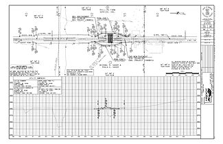
Plan-profile sheets are prepared to such a scale and in such detail required to accurately represent existing features and to convey details and quantities for the proposed work.
237.4.1 Preparation
Plan-profile sheets are developed using MoDOT’s supported CADD software. These procedures are to be followed when preparing plan-profile sheets. All design geometry including horizontal and vertical alignments are generated using MoDOT’s supported engineering design softare. Duplication of sheets covering the same area is avoided where practical. The use of matchlines is highly encouraged.
| Figure |
| An example of spiral data |
| Typical Section Forms |
| Rural and Urban Typical Roadway Sections |
The plan-profile sheets include details for profiles and grades for all intersected roads, crossroads, interchange ramps, outer roadways, bypasses, and all other items that are to be constructed. If such items cannot be shown on the main roadway plan-profile sheets without crowding, supplemental plan-profile sheets or full profile sheets are used. The delineation of pavements is shown, but the pavements are not shaded or colored. The delineation of other surface types is not usually shown. Profiles of ditch lines that vary from a standard ditch depth may be delineated on the roadway profiles or shown on cross sections or computer sheets.
237.4.2 Scale
The plan portion of plan-profile sheets is usually developed to a scale of 1 in. = 100 ft. Urban plans in highly developed areas sometimes require the use of a scale of 1 in. = 20 ft. to avoid crowding. The profile is plotted on the profile portion of the plan-profile sheet to the same horizontal scale used on the plan portion of the sheet. The profile is always plotted to a vertical scale of 1 in. = 10 ft., regardless of the horizontal scale used.
237.4.3 Sheet Numbers
Refer to EPG 237.13.4 Index of Sheets for guidance on numbering sheets. Full profile sheets are numbered subsequent to the main roadway plan-profile sheet on which the features appear. Supplemental plan-profile sheets, such as those for a crossroad, are also numbered subsequent to the main roadway plan-profile sheet on which those features appear.
237.4.4 Benchmarks
A description of benchmark locations and benchmark elevations is included in the profile portion of the plan-profile sheet.
237.4.5 Curve Data
Curve data for all horizontal curves is shown in accordance with the curve data illustrated on the examples in Figure 237.4.1 (to be develeoped from Section 4-10). The radius (arc) definition of curvature is used for new alignment. The chord definition is used only when an existing chord defined curve is utilized in the alignment. Chord definition curves are identified by placing “(chord)” after the radius listed in the curve data on the plans. An example of spiral data is provided for guidance. For complex interchanges or other projects, special curve data sheets may be developed to avoid clutter.
237.4.6 General Notes
Most general notes are shown on the first plan-profile sheet. Some examples of these notes are as follows:
- “Any items of work beyond the project limits are incidental to, and a part of the construction of this project.”
- “Bearings shown are state plane bearings, central zone.”
- “Federal improvement begins at a point approximately 1040 ft. east and 105 ft. north of SW COR SEC 1, T57N, R21W.”
237.4.7 Interchanges
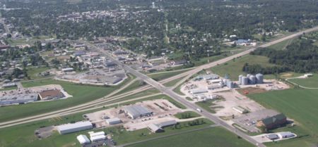
Plan-profile sheets covering interchange areas are developed to the same scale used for the main roadway. Details in interchange areas include all grading quantities, paving limits, and adequate provision for handling temporary and permanent drainage. Duplication of information on duplicate plan-profile sheets in interchange areas is not necessary or desirable.
237.4.7.1 Diamond-Type Interchanges. Details for diamond-type interchanges are developed on plan-profile sheets by using the sheet along the main roadway through the interchange and a supplemental plan-profile sheet for the crossroad. Ramp profiles and grades are shown on the profile section of the crossroad plan-profile sheet, if there is sufficient room without crowding. If not, a separate full profile sheet is used for the ramp profiles and grades.
237.4.7.2 Other Interchange Types. A full plan sheet, supplementing the plan-profile sheets for the main roadways through the interchange area, is used to develop geometric data and details for interchange types other than the diamond-type. Full profile sheets are used to develop profiles and grades for the interchange ramps and for outer roadways and service roads adjacent to the interchange area.
237.4.8 Reference Point Sheet
The reference points for the surveyed alignment are indicated on a separate sheet for use by Construction and Materials in re-establishing the location. Reference point sheets are available as a MicroStation seed file. The reference points are shown on a single sheet, if possible.
MoDOT Modified Coordinates (ground coordinates) should be placed on the Referenced Points Sheet. If Missouri State Plane Coordinates are shown, then a note needs to be added to the sheet identifying the coordinate as state plane.
237.4.9 Coordinate Point Sheet
| Pdf file of Coordinate Point Sheet |
| --- |
| Coordinate Point Sheet example |
In order to aid in the re-establishment of the alignment for a project, a listing of significant alignment and control points with their MoDOT Modified State Plane Coordinates (ground coordinates) are included in the plans on the Coordinate Point Sheet. A blank form is available as a MicroStation seed file. This listing includes the sheet number, station, location, offset, northing coordinate, easting coordinate, description of the significant points, and GPK point ID. The coordinates for the points are shown in feet to two decimal places (three decimals places for metric projects) but may be shown with up to five decimal places.
The points listed include the following:
- Beginning and ending station coordinates of project.
- Alignment points (POTs, PIs, Curves [PC, CC, PT], and Spiral Curves [TS, SC, Overall PI, CS, ST]).
- Major centerline intersections (e.g. state routes, major side road approaches, ramp intersections, outer roads, etc.).
- Survey Control Points used by Survey Crews.
- Other significant points unique to the project.
This sheet is used on all projects that have MoDOT Modified State Plane Coordinates. This sheet is not used on projects that have independent grid coordinates. The State Land Surveyor gave MoDOT exceptions to RSMo 60.431 so that MoDOT may publish coordinates in US Survey Feet and using MoDOT Modified State Plane Coordinates if the Coordinate Point Sheet clearly identifies them as such and provides the conversion factor to calculate State Plan Coordinates in Meters.
All coordinates listed are MoDOT Modified State Plane Coordinates (ground coordinates). This is to eliminate the confusion some contactors are having with State Plane Coordinates. The average grid factor used for the computation of the coordinates for the project is included on the sheet. The stations, offset distances, and coordinates shown on this sheet are ground distances. The point ID is the point number or name used in the computations.
The coordinate point sheet contains the historical data for the alignment information for the project and is a permanent part of the plans.
237.4.10 Typical Section Sheets
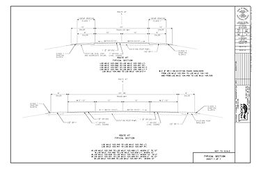
Typical section sheets are included in plans and show details and complete dimensions for proposed surfaces, bases, shoulders, ditches, and cut and fill slopes. The existing typical section information may be shown or summarized in a list on the typical section sheet when necessary. The typical section sheets include items such as pavement and shoulder dimensions, type, etc., to be constructed for highways, ramps, outer roadways, crossroads, and bypasses. Typical section sheets are numbered as sheet 2, regardless of the number of typical section sheets required. If more than one sheet is required the sheets are numbered “Sheet 1 of _____”, “Sheet 2 of _____”, etc.
Typical roadway sections are to be developed as reproducible line drawings based on MoDOT's established criteria. (MoDOT users with access to ProjectWise can access these drawings under CADD Standards>>Seed Files>>Design-English.) These typical sections can also be obtained from the "Figures" box near the top of this article. These drawings are available to the district on CADD and are used where applicable or where they can be adapted with a reasonable amount of revision.
If a reproducible line drawing cannot be used, typical section sheets must be developed. The arrangement and details on such sheets shall reflect the established typical section criteria. Typical section sheets are developed to scale. A distorted vertical scale is usually used to show surface and base thicknesses. The distorted scale is not applied to slopes so that a proper perspective is maintained.
Typical sections are based on the standard typical sections. For six-lane divided pavements (3 lanes each direction either initial or proposed), the inner four lanes slope toward the median and the outer two lanes slope away from the median, at 2.0 percent. For four-lane undivided pavements (2 lanes each direction) the lanes are sloped away from the profile grade point at 2.0 percent with no rounding at the centerline. When three or more lanes are inclined in the same direction on multilane pavements, the slope for each successive pair of lanes or portion thereof outward from the first two lanes from the crown line may be increased by a rate of 0.5 percent. A maximum of two lanes on each side of the crown line may be pitched at 1.5 percent. The selected cross-slopes are to be based upon pavement drainage and constructability.
237.4.11 Special Sheets
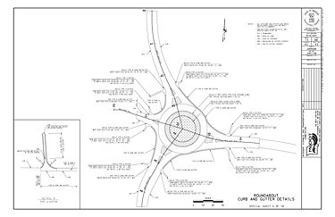
Special sheets supplement the plan-profile sheets. Information is preferably shown on plan-profile sheets where practicable. Special sheets are used in plans to enlarge details and to show details that cannot be shown on the plan-profile sheets. Duplication of information is not desirable. The special sheets are cross-referenced to and from the plan-profile sheets.
Special sheets are prepared in the same manner as plan-profile sheets. The scale selected for use on special drawings depends on the detail to be shown. Where applicable, a graphic scale is included on special sheets. If room allows, one special sheet may show several different details.
Special sheets are numbered consecutively after the plan-profile sheets, beginning with Special Sheet No. 1, preferably in the order the special drawings are required, proceeding from the beginning of the project in the direction of the survey. Where box culverts are designed for excess fills, a standard special sheet is included in the plans. This sheet is always numbered Special Sheet No. 1, and is completed with the required data.
Standard plans that are modified and used in plans are considered special sheets. Special sheets are used to show details and pavement joint layouts at ramp intersections and other intersections that are to be paved, where the details are not covered on standard plans. The scale used for the pavement layout sheet is from 1 in. = 30 ft. to 1 in. = 50 ft. (1:200 to 1:500), depending upon the amount of detail to be indicated. The lighting, signals, signing, and traffic control plans for a project may also be shown on special sheets. For additional information, refer to highway lighting, signals, highway signing, and traffic control plans.
237.4.12 Erosion and Sediment Control Sheets
The erosion and sediment control sheets are used to identify the appropriate type and location of erosion and sediment control best management practices (BMPs) to be used on a project. Erosion and sediment control plans not only provide a plan for installation of BMPs but also act as site plans for a project’s specific Stormwater Pollution Prevention Plan (SWPPP).
Effective erosion and sediment control plans shall contain sufficient BMPs to:
- Control stormwater volume and velocity within the site to minimize soil erosion;
- Control stormwater discharges, including both peak flow rates and total stormwater volume, to minimize erosion at outlets and downstream channel and stream bank erosion;
- Address factors such as amount, frequency, intensity and duration of precipitation to minimize soil discharges from the construction site;
- Provide buffers to surface waters of 50 ft. or BMPs adequate to achieve equal sediment load reduction as the 50 ft. natural buffer; and
- Where feasible, design to direct stormwater to vegetated areas to increase sediment removal and maximize infiltration.
Where water discharges from disturbed areas that will leave the project site, that water shall pass through either a sediment basin, a sediment trap, silt fence, and/or ditch checks. These elements shall be detailed on the erosion and sediment control plans. Areas where water discharges to another regulated municipal separate storm sewer system (MS4) shall also be shown on the erosion and sediment control plans.
Erosion and sediment control plans should be provided for each phase or stage of construction. As projects move from phase to phase, alterations to BMP types and locations may be necessary to comply with permit requirements.
See EPG 806 for erosion control and sediment control design considerations and SWPPP information.
237.4.13 Culvert Section Sheets
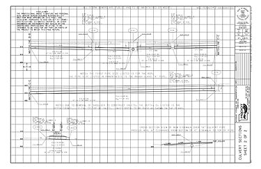
Culvert section sheets are used to detail drainage structures, including storm and sanitary sewers. The culvert section is a longitudinal section along the structure, and details are drawn accordingly. The existing ground line, station location, skew, survey centerline ground elevation and survey centerline profile elevation are shown. A horizontal and vertical scale of either 1 in. = 5 ft. or 1 in. = 10 ft. (1:50 or 1:100) is used. Culvert details are shown only to the extent necessary to indicate flow line elevations and the limits of Class 3 or 4 Excavation. Normal roadway excavation is excluded from Class 3 or 4 Excavation to avoid double payment. The standard plans pertaining to the culverts or drop inlets included in the project must be referenced on the culvert section sheets and are also to be listed on the 2B sheet of the project plans. The fill heights for the culvert sections and the type of end sections for both the upstream and downstream ends of the culverts must also be included (see Box Culverts Built in Sections and Modified Culverts although precise details of end sections or headwalls are not necessary or desirable. Each culvert section includes a note indicating the station location of the structure, the skew, the size of structure, the length of structure and the volume of Class 3 or 4 Excavation.
237.4.14 Bridge Drawings
Bridge drawings are prepared by Bridge and are assembled into the completed plans by Design.
237.4.15 Signal, Signing and Lighting Plans
Refer to EPG 901.10 Preparation of Plans for guidance on how to prepare lighting plan sheets.
Refer to EPG 902.15 Designing a Traffic Signal for guidance on how to prepare signal plan sheets.
Refer to EPG 903.2.25 Design Aspects of Signing for guidance on how to prepare signing plan sheets.
237.4.16 Standard Plans
Standard plans are used to eliminate the need for preparing detail drawings covering repetitious items for detail plans. Standard plans are used with plans in all cases where such drawings are adaptable, or where such drawings can be made adaptable by minor revisions, thereby eliminating the need for developing detailed drawings. Standard plans that are modified become special sheets. During the preparation of plans, the designer maintains a list of standard plans used to avoid overlooking items covered by standard plans upon completion of the plans.
237.4.17 Cross-Sections
Cross-sections are used to indicate and compute grading quantities necessary to construct the improvement to the required typical section and grade. Since cross-section sheets are not microfilmed, caution is to be taken by the designer not to include permanent record information on them.
The existing ground line, station location and survey centerline elevation are shown. A scale of either 1 in. = 5 ft. or 1 in. = 10 ft. is used. The grading limits are drawn on cross-sections by using a template. Rounding and overbreak are not shown. End areas and quantities are shown. End areas and quantities for excavation are total quantities. End areas and excavation quantities for classified excavation are not shown. Cross-section sheets are numbered consecutively, beginning with Sheet No. 1 for the first cross-section sheet for the project.