231.2 Clear Zones: Difference between revisions
m remove "Key Points" box |
m Clarified options when bridge or culvert headwall is in clear zone. |
||
| Line 45: | Line 45: | ||
The use of [[:Category:231 Typical Section Elements for Roadways|clear zone typical sections]] is not applicable to small culvert replacement projects where the intent is to continue the service of the road without upgrading it. In such cases, the typical sections used in the original construction are to be used except that the roadbed width is not to be more narrow than 24 ft. | The use of [[:Category:231 Typical Section Elements for Roadways|clear zone typical sections]] is not applicable to small culvert replacement projects where the intent is to continue the service of the road without upgrading it. In such cases, the typical sections used in the original construction are to be used except that the roadbed width is not to be more narrow than 24 ft. | ||
In shallow fills and in cuts where box or pipe culvert normally require a headwall to be located in the clear zone, the structure | In shallow fills and in cuts where box or pipe culvert normally require a headwall to be located in the clear zone, the structure should be extended to place the headwall at the outside of the clear zone or a safety appurtenance (guardrail or barrier) should be provided. The slope of the clear zone will then require modification over the entire surface. | ||
===231.2.4 On Ramps=== | ===231.2.4 On Ramps=== | ||
Revision as of 15:00, 12 November 2009

231.2.1 Introduction
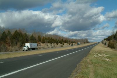
The clear zone is a roadside border area that is available for the safe use by errant vehicles as determined in accordance with Chapter 3 of the AASHTO Roadside Design Guide (RDG). It is measured from the edge of the travelway pavement.
In general, there are four methods of providing a clear zone. They are the preferred methods to attain roadside safety. In order of preference, they are:
- 1) Remove the obstacle.
- 2) Redesign the obstacle so it can be safely traversed.
- 3) Relocate the obstacle to where it is less likely to be struck.
- 4) Reduce impact severity by using an appropriate breakaway device.
Clear zone widths are most affected by the traffic’s speed and volume and the slope of the area adjacent to the travelway. Appropriate clear zones are selected for projects using Figure 3.1 from the RDG after consulting the location study report.
Clear zones are provided where the anticipated posted speed of the roadway is 45 mph or more. When the anticipated posted speed is less than 45 mph, clear zones are still beneficial but they are to be considered only if economically feasible. Non-traversable slopes or fixed objects are to be removed, relocated or shielded by a barrier if they are within the indicated minimum clear zone width and it is cost effective to do so. Higher speeds result in vehicles traveling farther off the travelway before control is recovered. Horizontal curvature increases the likelihood of a vehicle leaving the travelway and increases the distance it travels. The designer may choose to modify the clear zone distance obtained from RDG Figure 3.1 by using Table 3.2 (adjusting the values for horizontal curvature as necessary). These modifications are normally only considered where accident histories indicate a need, or a specific site investigation shows a definite accident potential which could be significantly lessened by increasing the clear zone width and such increases are cost-effective. Steeper slopes adjacent to the travelway increases the distance the vehicle travels beyond the travelway. In the implementation of the clear zone concept it is important for clear zone distances to not be used as boundaries for introducing roadside hazards such as bridge piers or trees. These are to be as far from the travelway as practical.

The clear zone width is to be applied with good judgment. If an obstacle lies just beyond the clear zone, it is to be removed or shielded if costs are reasonable. Conversely, the clear zone is not to be obtained at all costs. Limited right of way or high construction costs may lead to the installation of a barrier or possibly no protection at all. As may be noted, roadside slopes apply an important part in the clear zone width determination. Fill slopes of 1V:6H/1V:3H are preferred in areas of high fill, that is, a 1V:6H slope extending from the shoulder line out for a distance necessary to obtain the clear zone then break the slope to 1V:3H or flatter. If feasible, the flattening of slopes is preferable to installation of guardrail. In cut sections, the roadside ditch is likely to be located within the clear zone. Therefore, the configuration of the ditch and the type of erosion control treatment used in the ditch must be viewed with respect to clear zone requirements. Namely, side slopes of the ditch and the method of erosion control used in the ditch must be traversable by vehicles that leave the roadway. Figure 3.6 in the RDG is to be checked for preferred ditch cross-sections. Ditch sections must be within the shaded portions of the guides for use with clear zones. Background for this procedure is contained in Appendix A of the RDG. Any deviation from the preferred slope will be considered a special condition and is to be justified by costs or other considerations.
231.2.2 Clear Zone Perception Issues
In most cases, the use of the clear zone concept is preferable to the use of a shielding barrier. There is, however, a notable exception.
Occasionally the public will poorly perceive the clear zone concept. In areas of very high fills, particularly those on the outside of a horizontal curve, the clear zone alone may give the impression of an unsafe situation. Even though the design may be completely safe within the guidance of the RDG the public will inevitably request the area be shielded, most often with guardrail.
In these cases, the best practice is to initially specify shielding. By doing so, MoDOT can avoid the needless expense of eventually using both treatments in the same location.
231.2.3 For Bridges and Culverts
Clear zones, when used, shall extend full-width to bridge ends. Where the existing roadway is to be incorporated into the completed facility as part of the main roadway, the use of clear zones will be considered on individual projects.
The use of clear zone typical sections is not applicable to small culvert replacement projects where the intent is to continue the service of the road without upgrading it. In such cases, the typical sections used in the original construction are to be used except that the roadbed width is not to be more narrow than 24 ft.
In shallow fills and in cuts where box or pipe culvert normally require a headwall to be located in the clear zone, the structure should be extended to place the headwall at the outside of the clear zone or a safety appurtenance (guardrail or barrier) should be provided. The slope of the clear zone will then require modification over the entire surface.
231.2.4 On Ramps
Flattened slopes or clear zones are to be used on ramps to eliminate the use of guardrail. Use guardrail only to protect bridge ends within the interchange area.
231.2.5 In Unusual Conditions
When a standard clear zone width and slope will not properly terminate on the existing ground surface because of hilly conditions, steeper slopes must be used. In this case, the clear zone may be omitted and guardrail used at the shoulder line. The desirable minimum length for the elimination of clear zone is 500 ft. but in no case less than 250 ft.
For long fill sections through a reservoir project, clear zones can be eliminated and guardrail used at the shoulder lines.
Speed change lanes adjacent to main roadway are to be placed within main roadway's clear zone with no widening of clear zone. The clear zone is always located adjacent to and measured from the normal edge of the pavement of the main roadway including climbing or continuous auxiliary lanes.
231.2.6 Maintenance
District personnel shall be responsible for maintaining clear zones on highway improvement projects.