Difference between revisions of "903.6 Warning Signs"
m (→903.6.22 Low Clearance Sign (W12-2 and W12-2a) (MUTCD Section 2C.27): Per TR, clarified the policy. No new information.) |
|||
| Line 853: | Line 853: | ||
:* On routes greater than 10 miles from Interstate and designated highway network routes = 13 ft. 6 in. statutory maximum vehicle height (15’ 0” maximum posting). | :* On routes greater than 10 miles from Interstate and designated highway network routes = 13 ft. 6 in. statutory maximum vehicle height (15’ 0” maximum posting). | ||
| − | For specific details on commercial zone limits and designated highway network routes see Missouri Vehicle Route Map (map inset). | + | For specific details on commercial zone limits and designated highway network routes, see [https://www.modot.org/media/14314 Missouri Vehicle Route Map] ([https://www.modot.org/media/14315 map inset]). |
Posting requirements for Low Clearance signs are as follows: | Posting requirements for Low Clearance signs are as follows: | ||
Revision as of 07:35, 12 July 2019
Contents
- 1 903.6.1 Function of Warning Signs (MUTCD Section 2C.01)
- 2 903.6.2 Application of Warning Signs (MUTCD Section 2C.02)
- 3 903.6.3 Design of Warning Signs (MUTCD Section 2C.03)
- 4 903.6.4 Size of Warning Signs (MUTCD Section 2C.04)
- 5 903.6.5 Sight Distance
- 6 903.6.6 Placement of Warning Signs (MUTCD Section 2C.05)
- 7 903.6.7 Horizontal Alignment Signs (W1-1 through W1-5, W1-11, W1-15, W24-1L, W24-1cP) (MUTCD Section 2C.07)
- 7.1 903.6.7.1 Turn and Curve Signs (W1-1, W1-2)
- 7.2 903.6.7.2 Reverse Turn and Reverse Curve Signs (W1-3, W1-4)
- 7.3 903.6.7.3 Winding Road Sign (W1-5)
- 7.4 903.6.7.4 Hairpin Curve (W1-11) and 270-Loop Signs (W1-15)
- 7.5 903.6.7.5 Double Reverse Curve Left Sign (W24-1L) – Diverging Diamond Interchange (DDI) Application
- 7.6 903.6.7.6 ALL LANES Supplemental Plaque (W24-1cP) – Diverging Diamond Interchange (DDI) Application
- 7.7 Table 903.6.7 Horizontal Alignment Sign Usage
- 8 903.6.8 Combination Horizontal Alignment/Advisory Speed Sign (W1-1a, W1-2a) (MUTCD Section 2C.10)
- 9 903.6.9 Combination Horizontal Alignment/Intersection Signs (W1-10 Series) (MUTCD Section 2C.11)
- 10 903.6.10 One-Direction Large Arrow Sign (W1-6) (MUTCD Section 2C.12)
- 11 903.6.11 Chevron Alignment Sign (W1-8) (MUTCD Section 2C.09)
- 12 903.6.12 Truck Rollover Warning Sign (W1-13) (MUTCD Section 2C.13)
- 13 903.6.13 Hill Signs (W7-1) (MUTCD Section 2C.16)
- 14 903.6.14 Hill-Related Supplemental Plaques (W7-3 Series) (MUTCD Section 2C.57)
- 15 903.6.15 ROAD NARROWS Sign (W5-1) (MUTCD Section 2C.19)
- 16 903.6.16 NARROW BRIDGE Sign (W5-2) (MUTCD Section 2C.20)
- 17 903.6.17 ONE LANE BRIDGE Sign (W5-3) (MUTCD Section 2C.21)
- 18 903.6.18 Divided Highway Sign (W6-1) (MUTCD Section 2C.22)
- 19 903.6.19 Divided Highway Ends Sign (W6-2) (MUTCD Section 2C.23)
- 20 903.6.20 Double Arrow Sign (W12-1) (MUTCD Section 2C.25)
- 21 903.6.21 DEAD END, NO OUTLET and ROAD ENDS Signs (W14-1, W14-2, W14-13) (MUTCD Section 2C.26)
- 22 903.6.22 Low Clearance Sign (W12-2 and W12-2a) (MUTCD Section 2C.27)
- 23 903.6.23 BUMP and DIP Signs (W8-1, W8-2) (MUTCD Section 2C.28)
- 24 903.6.24 PAVEMENT ENDS Sign (W8-3) (MUTCD Section 2C.30)
- 25 903.6.25 SOFT SHOULDER Sign (W8-4) (MUTCD Section 2C.31)
- 26 903.6.26 Slippery When Wet Sign (W8-5) (MUTCD Section 2C.32)
- 27 903.6.27 FALLEN ROCKS Sign (W8-14) (MUTCD Section 2C.32)
- 28 903.6.28 Advance Traffic Control Signs (W3-1, W3-2, W3-3, W3-4) (MUTCD Section 2C.36)
- 29 903.6.29 Advance Ramp Control Signal Signs (W3-7 and W3-8) (MUTCD Section 2C.37)
- 30 903.6.30 Reduced Speed Limit Ahead Signs (W3-5) (MUTCD Section 2C.38)
- 31 903.6.31 Merge Signs (W4-1, W4-5) (MUTCD Section 2C.40)
- 32 903.6.32 Added Lane Signs (W4-3, W4-6) (MUTCD Section 2C.41)
- 33 903.6.33 LANE END Signs (W4-2, W9-1, W9-2) (MUTCD Section 2C.42)
- 34 903.6.34 Two-Way Traffic Sign (W6-3, W16-9P) (MUTCD Section 2C.44)
- 35 903.6.35 NO PASSING ZONE Sign (W14-3) (MUTCD Section 2C.45)
- 36 903.6.36 Advisory Exit and Ramp Speed Signs (W13-2 and W13-3) (MUTCD Section 2C.14)
- 37 903.6.37 Intersection Warning Signs (W2-1 through W2-8) (MUTCD Section 2C.46)
- 38 903.6.38 Two-Direction Large Arrow Sign (W1-7) (MUTCD Section 2C.47)
- 39 903.6.39 Traffic Signal Signs (W25-1, W25-2) (MUTCD Section 2C.48)
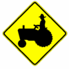
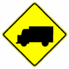
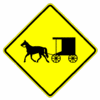
- 40 903.6.40 Vehicular Traffic Warning Signs (W11-1, W11-1b, W11-5, W11-8, W11-10, W11-12P, W11-14) (MUTCD Section 2C.49)
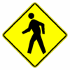
- 41 903.6.41 Non-Vehicular Warning Signs (W11-2, W11-3, W11-4, W11-7, W11-32, W11-33, W16-9P) (MUTCD Section 2C.50)
- 42 903.6.42 FERRY CROSSING AHEAD Sign (W3-18)
- 43 903.6.43 Use of Supplemental Warning Plaques (MUTCD Section 2C.53)
- 44 903.6.44 Design of Supplemental Warning Plaques (MUTCD Section 2C.54)
- 45 903.6.45 Distance Supplemental Plaques (W16-2 Series, W16-3 Series, W16-4P, W7-3aP) (MUTCD Section 2C.55)
- 46 903.6.46 Advisory Speed Supplemental Plaque (W13-1P) (MUTCD Section 2C.08)
- 47 903.6.47 Supplemental Arrow Plaque (W16-5P, W16-6P) (MUTCD Section 2C.56)
- 48 903.6.48 Advance Street Name Supplemental Plaque (W16-8P, W16-8aP) (MUTCD Section 2C.58)
- 49 903.6.49 CROSS TRAFFIC DOES NOT STOP Plaque (W4-4P) (MUTCD Section 2C.59)
- 50 903.6.50 SHARE THE ROAD Supplemental Plaque (W16-1P) (MUTCD Section 2C.60)
- 51 903.6.51 PHOTO ENFORCED Plaque (W16-10aP) (MUTCD Section 2C.61)
- 52 903.6.52 IMPASSABLE DURING HIGH WATER Sign (W8-18, W8-19a, W8-34, W8-35) (MUTCD Section 2C.35)
- 53 903.6.53 Hazard Communication Signs
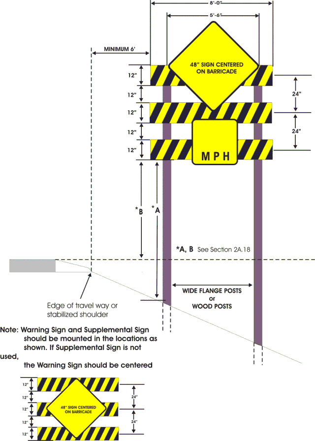
- 54 903.6.54 Sign Barricades (MUTCD Section 2B.67)
- 55 903.6.55 Shoulder Barricade Assembly
- 56 903.6.56 Warning Signs Provided for Other Agencies
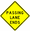
- 57 903.6.57 Passing Lane Warning Signs (W6-6a, W6-6aP, W6-16, W6-17)
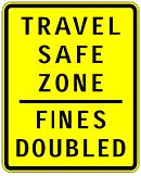
- 58 903.6.58 TRAVEL SAFE ZONE – FINES DOUBLED Sign (W26-1)
- 59 903.6.59 NOTICE Plaque (W16-18P) (MUTCD Section 2A.15)
903.6.1 Function of Warning Signs (MUTCD Section 2C.01)
Support. Warning signs call attention to unexpected conditions on or adjacent to a highway, street or private road open to public travel and to situations that might not be readily apparent to road users. Warning signs alert road users to conditions that might call for a reduction of speed or an action in the interest of safety and efficient traffic operations.
903.6.2 Application of Warning Signs (MUTCD Section 2C.02)
Standard. The use of warning signs shall be based on an engineering study or on engineering judgment.
Guidance. The use of warning signs should be kept to a minimum as the unnecessary use of warning signs tends to increase disrespect for all signs. In situations where the condition or activity is seasonal or temporary, the warning sign should be removed or covered when the condition or activity does not exist.
Option. Consistent with the provisions of the EPG, changeable message signs may be used to display a warning message. Consistent with the provisions of EPG 902.12.3, a Warning Beacon may be used in combination with a standard warning sign.
Support. The categories of Warning signs are shown in Table 903.6.2. Warning signs provided in EPG 903 cover most of the conditions that are likely to be encountered. Additional warning signs for temporary traffic control zones, school areas, grade crossings and bicycle facilities are discussed in EPG 903.19 Signing for School Areas, EPG 903.20 Signing for Rail and Light Rail Transit Grade Crossings and EPG 903.21 Signing for Bicycle Facilities.
Option. Word message warning signs other than those specified in this article may be developed and installed.
Table 903.6.2 Categories of Warning Signs and Plaques
| Category | Group | EPG Article | Signs or Plaques | Sign Numbers |
|---|---|---|---|---|
| Roadway Related | Changes in Horizontal Alignment | 903.6.7 | Turn, Curve, Reverse Turn, Reverse Curve, Winding Road, Hairpin Curve | W1-1, 2, 3, 4, 5, 11, 15 |
| 903.6.46 | Advisory Speed | W13-1P | ||
| 903.6.11 | Chevron Alignment | W1-8 | ||
| 903.6.8 | Combination Horizontal Alignment/Advisory Speed | W1-1a, 2a | ||
| 903.6.9 | Combination Horizontal Alignment/Intersection | W1-10, 10a, 10b, 10c, 10d | ||
| 903.6.10 | Large Arrow (one direction) | W1-6 | ||
| 903.6.12 | Truck Rollover | W1-13 | ||
| 903.6.36 | Advisory Exit or Ramp Speed | W13-2, 3 | ||
| Vertical Alignment | 903.6.13 | Hill | W7-1, 1a, 2P, 2bP, 3P, 3aP, 3bP | |
| Cross-Section | 903.6.15 | Road Narrows | W5-1 | |
| 903.6.16, 903.6.17 | Narrow Bridge, One Lane Bridge | W5-2, 3 | ||
| 903.6.18 - 903.6.20 | Divided Highway, Divided Highway Ends, Double Arrow | W6-1, 2; W12-1 | ||
| 903.6.21 | Dead End, No Outlet | W14-1, 1a, 2, 2a | ||
| 903.6.22 | Low Clearance | W12-2, 2a | ||
| Roadway Surface Condition | 903.6.23 | Bump, Dip | W8-1, 2 | |
| 903.6.24 | Pavement Ends | W8-3 | ||
| 903.6.25 | Soft Shoulder | W8-4 | ||
| 903.6.26, 903.6.27 | Slippery When Wet, Fallen Rocks | W8-5, 20 | ||
| Weather | 903.6.52 | Road May Flood, Flood Gauge, Gusty Winds Area, Fog Area | W8-18, 19, 21, 22 | |
| Traffic Related | Advance Traffic Control | 903.6.28 - 903.6.30 | Stop Ahead, Yield Ahead, Signal Ahead, Be Prepared To Stop, Speed Reduction, Ramp Meter Ahead | W3-1,
2, 3, 4, 5, 5a, 6, 7, 8 |
| Traffic Flow | 903.6.31 - 903.6.36 | Merge, No Merge Area, Lane Ends, Added Lane, Two-Way Traffic, Right Lane Exit Only Ahead, No Passing Zone | W4-1, 2, 3, 5, 5P, 6; W6-3;W9-1, 2, 7; W14-3 | |
| Intersections | 903.6.37 | Crossroad, Side Road, T, Y, Circular Intersection, Side Roads | W2-1, 2, 3, 4, 5, 6, 7, 8; W16-12P, 17P | |
| 903.6.38 | Large Arrow (two direction) | W1-7 | ||
| 903.6.39 | Oncoming Extended Green | W25-1, 2 | ||
| Vehicular Traffic | 903.6.40 | Truck Crossing, Truck (symbol), Emergency Vehicle, Tractor, Bicycle, Golf Cart, Horse-Drawn Vehicle, Trail Crossing | W8-6; W11-1, 5, 5a, 8, 10, 11, 12P, 14, 15, 15P, 15a; W16-13P | |
| Non-Vehicular | 903.6.41 | Pedestrian, Deer, Cattle, Snowmobile, Equestrian, Wheelchair, Large Animals | W11-2, 3, 4, 6, 7, 9, 16, 17, 18, 19, 20, 21, 22; W16-13P | |
| Other Supplemental Plaques | Location | 903.6.56 | Downward Diagonal Arrow, Ahead | W16-7P, 9P |
| Distance | 903.6.45 | XX Feet, XX Miles, Next XX Feet, Next XX Miles | W7-3aP; W16-2P, 2aP, 3P, 3aP, 4P | |
| Arrow | 903.6.47 | Advance Arrow, Directional Arrow | W16-5P, 6P | |
| Street Name Plaque | 903.6.48 | Advance Street Name | W16-8P, 8aP | |
| Intersection | 903.6.49 | Cross Traffic Does Not Stop | W4-4P, 4aP, 4bP | |
| Share The Road | 903.6.50 | Share The Road | W16-1P | |
| Photo Enforced | 903.6.51 | Photo Enforced | W16-10P, 10aP |
903.6.3 Design of Warning Signs (MUTCD Section 2C.03)
Standard. Except as provided below or unless specifically designated otherwise, all warning signs shall be diamond-shaped (square with one diagonal vertical) with a black legend and border on a fluorescent yellow background. Warning signs shall be designed in accordance with the sizes, shapes, colors and legends contained in the Standard Highway Signs and Markings book.
Option. A warning sign that is larger than the size shown in the Oversized column in Table 903.6.3 for that particular sign may be diamond-shaped or may be rectangular or square in shape. Warning signs regarding conditions associated with pedestrians, bicyclists and playgrounds may have a black legend and border on a fluorescent yellow background.
Standard. Warning signs regarding conditions associated with school buses and schools and their related supplemental plaques shall have a black legend and border on a fluorescent yellow-green background (see EPG 903.19.9).
Table 903.6.3 Warning Sign and Plaque Sizes
| Sign or Plaque | Sign Designation | EPG Article | Conventional Road (in. x in.) | Freeway/Expressway (in. x in.) | ||
|---|---|---|---|---|---|---|
| Single Lane | Multi-Lane | Oversized | Mainline & Ramps | |||
| Turn | W1-1 | 903.6.7 | 36 X 36 | 36 X 36 | 48 X 48 | 48 X 48 |
| Curve | W1-2 | 903.6.7 | 36 X 36 | 36 X 36 | 48 X 48 | 48 X 48 |
| Reverse Turn | W1-3 | 903.6.7 | 36 X 36 | 36 X 36 | 48 X 48 | 48 X 48 |
| Reverse Curve | W1-4 | 903.6.7 | 36 X 36 | 36 X 36 | 48 X 48 | 48 X 48 |
| Winding Road | W1-5 | 903.6.7 | 36 X 36 | 36 X 36 | 48 X 48 | 48 X 48 |
| Hairpin Curve | W1-11 | 903.6.7 | 36 X 36 | 36 X 36 | 48 X 48 | 48 X 48 |
| 270° Curve | W1-15 | 903.6.7 | 36 X 36 | 36 X 36 | 48 X 48 | 48 X 48 |
| Double Reverse Curve Left | W24-1L | 903.6.7 | 36 X 36 | 36 X 36 | 48 X 48 | 48 X 48 |
| ALL LANES | W24-1cP | 903.6.7 | - | 24 X 18 | 36 X 24 | 36 X 24 |
| Combination Turn/Advisory Speed | W1-1a | 903.6.8 | 36 X 36 | 36 X 36 | 48 X 48 | 48 X 48 |
| Combination Curve/Advisory Speed | W1-2a | 903.6.8 | 36 X 36 | 36 X 36 | 48 X 48 | 48 X 48 |
| Combination Horizontal Alignment/Intersection | W1-10 | 903.6.9 | 36 X 36 | 36 X 36 | 48 X 48 | 48 X 48 |
| One-Direction Large Arrow | W1-6 | 903.6.10 | 48 X 24 | 48 X 24 | 72 X 36 | 72 X 36 |
| Chevron | W1-8 | 903.6.11 | 18 X 24 | 18 X 24 | 30 X 36 | 30 X 36 |
| Truck Rollover | W1-13 | 903.6.12 | - | - | - | 48 X 48 |
| Hill | W7-1 | 903.6.13 | 36 X 36 | 36 X 36 | 48 X 48 | 48 X 48 |
| ROAD NARROWS | W5-1 | 903.6.15 | 36 X 36 | 36 X 36 | 48 X 48 | 48 X 48 |
| NARROW BRIDGE | W5-2 | 903.6.16 | 36 X 36 | 36 X 36 | 48 X 48 | 48 X 48 |
| ONE LANE BRIDGE | W5-3 | 903.6.17 | 36 X 36 | 36 X 36 | 48 X 48 | 48 X 48 |
| Divided Highway | W6-1 | 903.6.18 | 36 X 36 | 36 X 36 | 48 X 48 | 48 X 48 |
| Divided Highway Ends | W6-2 | 903.6.19 | 36 X 36 | 36 X 36 | 48 X 48 | 48 X 48 |
| Double Down Arrow | W12-1 | 903.6.20 | 36 X 36 | 36 X 36 | - | - |
| DEAD END | W14-1 | 903.6.20 | 36 X 36 | 36 X 36 | 36 X 36 | 36 X 36 |
| NO OUTLET | W14-2 | 903.6.20 | 36 X 36 | 36 X 36 | 36 X 36 | 36 X 36 |
| ROAD ENDS | W14-13 | 903.6.20 | 36 X 36 | 36 X 36 | 36 X 36 | 36 X 36 |
| Low Clearance | W12-2 | 903.6.22 | 36 X 36 | 36 X 36 | 48 X 48 | 48 X 48 |
| LOW CLEARNACE (overhead) | W12-2a | 903.6.22 | - | - | - | 84 X 24 |
| PAVEMENT ENDS | W8-3 | 903.6.24 | 36 X 36 | 36 X 36 | - | - |
| SOFT SHOULDER | W8-4 | 903.6.25 | 36 X 36 | 36 X 36 | 48 X 48 | 48 X 48 |
| FALLEN ROCK | W8-14 | 903.6.27 | 36 X 36 | 36 X 36 | 48 X 48 | 48 X 48 |
| Stop Ahead | W3-1 | 903.6.28 | 36 X 36 | 36 X 36 | 48 X 48 | 48 X 48 |
| Yield Ahead | W3-2 | 903.6.28 | 36 X 36 | 36 X 36 | 48 X 48 | 48 X 48 |
| Signal Ahead | W3-3 | 903.6.28 | 36 X 36 | 36 X 36 | 48 X 48 | 48 X 48 |
| BE PREPARED TO STOP | W3-4 | 903.6.28 | 36 X 36 | 36 X 36 | 48 X 48 | 48 X 48 |
| Ramp Meter Ahead | W3-7 | 903.6.29 | 36 X 36 | 36 X 36 | - | - |
| Ramp Meter When Flashing | W3-8 | 903.6.29 | 36 X 36 | 36 X 36 | - | - |
| Reduced Speed Ahead | W3-5 | 903.6.30 | 36 X 36 | 36 X 36 | 48 X 48 | 48 X 48 |
| Merge | W4-1 | 903.6.31 | 36 X 36 | 36 X 36 | 48 X 48 | 48 X 48 |
| Entering Roadway Merge | W4-5 | 903.6.31 | 36 X 36 | 36 X 36 | 48 X 48 | 48 X 48 |
| Added Lane | W4-3 | 903.6.32 | 36 X 36 | 36 X 36 | 48 X 48 | 48 X 48 |
| Entering Roadway Added Lane | W4-6 | 903.6.32 | 36 X 36 | 36 X 36 | 48 X 48 | 48 X 48 |
| Lane Ends | W4-2 | 903.6.33 | 36 X 36 | 36 X 36 | 48 X 48 | 48 X 48 |
| Left (Right) Lane Ends | W9-1 | 903.6.33 | 36 X 36 | 36 X 36 | 48 X 48 | 48 X 48 |
| Lane Ends Merge Left (Right) | W9-2 | 903.6.33 | 36 X 36 | 36 X 36 | 48 X 48 | 48 X 48 |
| Two-Way Traffic | W6-3 | 903.6.34 | 36 X 36 | 36 X 36 | 48 X 48 | 48 X 48 |
| NO PASSING ZONE (pennant) | W14-3 | 903.6.35 | 48 X 30 | - | - | - |
| Advisory Exit Speed | W13-2 | 903.6.36 | - | - | - | 48 X 60 |
| Advisory Ramp Speed | W13-3 | 903.6.36 | - | - | - | 48 X 60 |
| Crossroad | W2-1 | 903.6.37 | 36 X 36 | 36 X 36 | 48 X 48 | 48 X 48 |
| Side Road | W2-2 | 903.6.37 | 36 X 36 | 36 X 36 | 48 X 48 | 48 X 48 |
| Side Road (45°) | W2-3 | 903.6.37 | 36 X 36 | 36 X 36 | 48 X 48 | 48 X 48 |
| T Intersection | W2-4 | 903.6.37 | 36 X 36 | 36 X 36 | 48 X 48 | 48 X 48 |
| Y Intersection | W2-5 | 903.6.37 | 36 X 36 | 36 X 36 | 48 X 48 | 48 X 48 |
| Circular Intersection | W2-6 | 903.6.37 | 36 X 36 | 36 X 36 | 48 X 48 | 48 X 48 |
| Two-Direction Large Arrow | W1-7 | 903.6.38 | 48 X 24 | 48 X 24 | 72 X 36 | 72 X 36 |
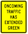
| TRAFFIC SIGNAL HAS EXTENDED GREEN | W25-1 | 903.6.39 | 24 X 30 | 24 X 30 | - | - |
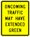
| TRAFFIC SIGNAL MAY HAVE EXTENDED GREEN | W25-2 | 903.6.39 | 24 X 30 | 24 X 30 | - | - |
| Bicycle | W11-1 | 903.6.40 | 36 X 36 | 36 X 36 | - | - |
| Farm Vehicle | W11-5 | 903.6.40 | 36 X 36 | 36 X 36 | 48 X 48 | 48 X 48 |
| Emergency Vehicle | W11-8 | 903.6.40 | 36 X 36 | 36 X 36 | 48 X 48 | 48 X 48 |
| Truck | W11-10 | 903.6.40 | 36 X 36 | 36 X 36 | 48 X 48 | 48 X 48 |
| Horse-Drawn Vehicle | W11-14 | 903.6.40 | 36 X 36 | 36 X 36 | 48 X 48 | 48 X 48 |
| Pedestrian | W11-2 | 903.6.41 | 36 X 36 | 48 x 48 | 48 X 48 | - |
| Downward Diagonal Arrow | W16-7P | 903.6.41 | 30 X 18 | 30 X 18 | 30 X 18 | 30 X 18 |
| Deer | W11-3 | 903.6.41 | 36 X 36 | 36 X 36 | 48 X 48 | 48 X 48 |
| Cattle | W11-4 | 903.6.41 | 36 X 36 | 36 X 36 | - | - |
| Equestrian | W11-7 | 903.6.41 | 36 X 36 | 36 X 36 | - | - |
| Duck | W11-32 | 903.6.41 | 36 X 36 | 36 X 36 | 48 X 48 | 48 X 48 |
| Pedestrian on Bridge | W11-33 | 903.6.41 | 36 X 36 | 36 X 36 | 48 X 48 | 48 X 48 |
| FERRY CROSSING AHEAD | W3-18 | 903.6.42 | 36 X 36 | 36 X 36 | 48 X 48 | 48 X 48 |
| _ FEET | W16-2P | 903.6.45 | 24 X 18 | 24 X 18 | 30 X 24 | 30 X 24 |
| _ MILES | W16-3P | 903.6.45 | 30 X 24 | 30 X 24 | 30 X 24 | 30 X 24 |
| NEXT _ FEET | W16-4P | 903.6.45 | 30 X 24 | 30 X 24 | 30 X 24 | 30 X 24 |
| NEXT _ FEET | W7-3a | 903.6.45 | 24 X 18 | 24 X 18 | 30 X 24 | 30 X 24 |
| Advisory Speed | W13-1P | 903.6.46 | 24 X 24 | 24 X 24 | 30 X 30 | 30 X 30 |
| Directional Arrow | W16-5P | 903.6.47 | 24 X 18 | 24 X 18 | 30 X 24 | 30 X 24 |
| Advance Turn Arrow | W16-6P | 903.6.47 | 24 X 18 | 24 X 18 | 30 X 24 | 30 X 24 |
| Percent Grade | W7-3P | 903.6.14 | 24 X 18 | 24 X 18 | 30 X 24 | 30 X 24 |
| Advance Street Name | W16-8P | 903.6.48 | Varies X 15 | Varies X 15 | Varies X 15 | Varies X 15 |
| CROSS TRAFFIC DOES NOT STOP | W4-4P | 903.6.49 | 36 X 18 | 36 X 18 | 36 X 18 | 36 X 18 |
| SHARE THE ROAD | W16-1P | 903.6.50 | 24 X 30 | 24 X 30 | - | 24 X 30 |
| PHOTO ENFORCED | W16-10aP | 903.6.51 | 36 X 24 | 36 X 24 | - | - |
| WATER OVER ROAD | W8-33 | - | 36 X 36 | 36 X 36 | 48 X 48 | 48 X 48 |
| IMPASSABLE DURING HIGH WATER | W8-34 | 903.6.52 | 36 X 36 | 36 X 36 | 48 X 48 | 48 X 48 |
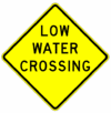
| LOW WATER CROSSING | W8-35 | 903.6.52 | 36 X 36 | 36 X 36 | - | - |
| Water Gauge | W8-19a | 903.6.52 | 9 X 48 | 9 X 48 | - | - |
| Passing Lane | W6-6a | 903.6.57 | 36 X 36 | 36 X 36 | - | - |
| PASSING LANE | W6-6aP | 903.6.57 | 42 X 12 | 42 X 12 | - | - |
| PASSING LANE ENDS | W6-16 | 903.6.57 | 36 X 36 | 36 X 36 | - | - |
| WATCH FOR LEFT-TURNING TRAFFIC IN PASSING LANE | W6-17 | 903.6.57 | 72 X 48 | 72 X 48 | - | - |
| TRAVEL SAFE ZONE | W26-1 | 903.6.58 | 36 X 48 | 36 X 48 | 48 X 60 | 48 X 60 |
903.6.4 Size of Warning Signs (MUTCD Section 2C.04)
Standard. Except as provided in EPG 903.2.21, the sizes for warning plaques shall be as shown in Table 903.6.4. Except as provided below, the minimum size for all diamond-shaped warning signs facing traffic on a multi-lane conventional road where the posted speed limit is higher than 35 mph shall be 36 in. x 36 inches.
Table 903.6.4, Minimum Size of Supplemental Warning Plaques
| Size of Warning Sign (in. x in.) | Size of Supplemental Plaque (in. x in.) | |||
|---|---|---|---|---|
| Rectangular | Square | |||
| 1 Line | 2 Lines | Arrow | ||
| 24 X 24 | 24 X 12 | 24 X 18 | 24 X 12 | 18 X 18 |
| 30 X 30 | ||||
| 36 X 36 | 30 X18 | 30 X 24 | 30 X 18 | 24 X 24 |
| 48 X 48 | ||||
Option. The smaller signs may be used on low-speed roadways where the reduced legend size would be adequate for the warning or where physical conditions preclude the use of the other sizes.
Larger sizes may be used for those special applications where speed, volume or other factors result in conditions where increased emphasis, improved recognition or increased legibility would be desirable.
Signs larger than those shown in Table 903.6.3 may be used with the approval of the State Traffic Engineer.
Guidance. The minimum size for all diamond-shaped warning signs facing traffic on exit and entrance ramps should be the same size sign as the mainline roadway classification.
903.6.5 Sight Distance
Support. The decision to use most warning signs is based on prevailing conditions. The items to be considered when determining the need for a warning sign are sight distance and prevailing speed. Prevailing speed is determined by using either the posted or 85th percentile speed on the facility. Sight distance is the distance a driver requires to perceive, react and respond to a condition. The prevailing speed affects the amount of sight distance required for a condition.
It is a recommended to use Table 903.6.5 to determine the sight distance needed when considering the use of most warning signs. If the sight distance is less than that in Table 903.6.5, a sign may be needed.
Table 903.6.5 Sight Distance Requirements
| Prevailing Speed (mph) | Distance (ft.) |
|---|---|
| 30 | 200 |
| 35 | 250 |
| 40 | 305 |
| 45 | 360 |
| 50 | 425 |
| 55 | 495 |
| 60 | 570 |
| 65 | 645 |
| 70 | 730 |
| Note: Based on the AASHTO Green Book, 2001 Edition, Exhibit 3-1 | |
903.6.6 Placement of Warning Signs (MUTCD Section 2C.05)
Support. For information on placement of warning signs, see EPG 903.3 and EPG 903.4.
The time needed for detection, recognition, decision, and reaction is called the Perception-Response Time (PRT).
Table 903.6.6 is provided as an aid for determining warning sign location. The distances shown in Table 903.6.6 can be adjusted for roadway features, other signing and to improve visibility.
Standard. The minimum visibility for warning signs shall be determined from Table 903.6.6.
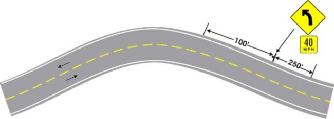
Guidance. Warning signs should be placed so that they provide an adequate PRT. The distances contained in Table 903.6.6 are for guidance purposes and should be applied with engineering judgment. Warning signs are not to be placed so far in advance of the condition that drivers tend to forget the warning because of other driving distractions, especially in urban areas.
Minimum spacing between warning signs with different messages should be based on the estimated PRT for driver comprehension of and reaction to the second sign. If an adjustment is necessary, every effort should be made to make it as small as possible.
The effectiveness of the placement of warning signs should be periodically evaluated. This is typically accomplished during routine sign inspection cycles.
Standard. When any part of a warning sign assembly (post, sign, plaque, etc.) is replaced, maintained or modified, the placement of the sign shall be reviewed based on the Table 903.6.6. Additionally, mounting height shall be reviewed for conformance with EPG 903.3.3 Mounting Height.
Option. Warning signs that advise road users about conditions that are not related to a specific location, such as Non-Vehicle signs or SOFT SHOULDER, may be installed in an appropriate location, based on engineering judgment, since they are not covered in Table 903.6.6.
Table 903.6.6 Guidelines for Advance Placement of Warning Sign
| Posted or 85th Percentile Speed | Advance Placement Distance1 | ||||||||
|---|---|---|---|---|---|---|---|---|---|
| Condition A: Speed reduction and lane changing in heavy traffic2 | Condition B: Deceleration to the listed advisory speed (mph) for the condition | ||||||||
| 03 | 104 | 204 | 304 | 404 | 504 | 604 | 704 | ||
| 20 mph | 225 ft. | 100 ft.6 | N/A5 | - | - | - | - | - | - |
| 25 mph | 325 ft. | 100 ft.6 | N/A5 | N/A5 | - | - | - | - | - |
| 30 mph | 460 ft. | 100 ft.6 | N/A5 | N/A5 | - | - | - | - | - |
| 35 mph | 565 ft. | 100 ft.6 | N/A5 | N/A5 | N/A5 | - | - | - | - |
| 40 mph | 670 ft. | 125 ft. | 100 ft.6 | 100 ft.6 | N/A5 | - | - | - | - |
| 45 mph | 775 ft. | 175 ft. | 125 ft. | 100 ft.6 | 100 ft.6 | N/A5 | - | - | - |
| 50 mph | 885 ft. | 250 ft. | 200 ft. | 175 ft. | 125 ft. | 100 ft.6 | - | - | - |
| 55 mph | 990 ft. | 325 ft. | 275 ft. | 225 ft. | 200 ft. | 125 ft. | N/A5 | - | - |
| 60 mph | 1100 ft. | 400 ft. | 350 ft. | 325 ft. | 275 ft. | 200 ft. | 100 ft.6 | - | - |
| 65 mph | 1200 ft. | 475 ft. | 450 ft. | 400 ft. | 350 ft. | 275 ft. | 200 ft. | 100 ft.6 | - |
| 70 mph | 1250 ft. | 550 ft. | 525 ft. | 500 ft. | 450 ft. | 375 ft. | 275 ft. | 150 ft. | - |
| 75 mph | 1350 ft. | 650 ft. | 625 ft. | 600 ft. | 550 ft. | 475 ft. | 375 ft. | 250 ft. | 100 ft.6 |
| Notes:
1 The distances are adjusted for a sign legibility distance of 180 ft. for Condition A. The distances for Condition B have been adjusted for a sign legibility distance of 250 ft., which is appropriate for an alignment warning symbol sign. For Conditions A and B, warning signs with less than 6 in. legend or more than four words, a minimum of 100 ft. should be added to the advance placement distance to provide adequate legibility of the warning sign. 2 Typical conditions are locations where the road user must use extra time to adjust speed and change lanes in heavy traffic because of a complex driving situation. Typical signs are Merge and Right Lane Ends. The distances are determined by providing the driver a PRT of 14.0 to 14.5 seconds for vehicle maneuvers (2005 AASHTO Policy, Exhibit 3-3, Decision Sight Distance, Avoidance Maneuver E) minus the legibility distance of 180 ft. for the appropriate sign. 3 Typical condition is the warning of a potential stop situation. Typical signs are Stop Ahead, Yield Ahead, Signal Ahead, and Intersection Warning signs. The distances are based on the 2004 AASHTO Policy, Exhibit 3-1, Stopping Sight Distance, providing a PRT of 2.5 seconds, a deceleration rate of 11.2 ft./sec2, minus the sign legibility distance of 180 feet. 4 Typical conditions are locations where the road user must decrease speed to maneuver through the warned condition. Typical signs are Turn, Curve, Reverse Turn, or Reverse Curve. The distance is determined by providing a 2.5 second PRT, a vehicle deceleration rate of 10 ft./sec2, minus the sign legibility distance of 250 feet. 5 No suggested distances are provided for these speeds, as the placement location is dependent on site conditions and other signing. An alignment warning sign may be placed anywhere from the point of curvature up to 100 ft. in advance of the curve. However, the alignment warning sign should be installed in advance of the curve and at least 100 ft. from any signs. 6 The minimum advance placement distance is listed as 100 ft. to provide adequate spacing between signs. | |||||||||
903.6.7 Horizontal Alignment Signs (W1-1 through W1-5, W1-11, W1-15, W24-1L, W24-1cP) (MUTCD Section 2C.07)
Support. A variety of horizontal alignment warning signs, pavement markings, and delineation can be used to advise motorists of a change in the roadway alignment. Uniform application of these traffic control devices with respect to the amount of change in the roadway alignment conveys a consistent message establishing driver expectancy and promoting effective roadway operations. The design and application of horizontal alignment warning signs to meet those requirements are addressed in EPG 903.6.7.1 through 903.6.7.6.
Standard. All horizontal alignment signs shall have an Advisory Speed Supplemental Plaque (W13-1P) mounted below the primary warning when the difference between the posted speed limit and the advisory speed is 5 mph or greater. See EPG 903.6.46 for additional guidance on the application of the Advisory Speed Supplemental Plaque (W13-1P).
Option. Horizontal alignment signs may be installed without the Advisory Speed Supplemental Plaque (W13-1P) if the alignment can be driven at or above the posted speed limit and engineering judgment indicates the need for the horizontal alignment sign for reasons other than speed differential.
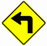
903.6.7.1 Turn and Curve Signs (W1-1, W1-2)
Standard. A Curve sign (W1-2) shall be used when the difference between the speed limit and advisory speed is 5 mph or greater, unless a different sign is recommended or allowed. A Turn sign (W1-1) shall be used instead of a Curve sign in advance of curves that have advisory speeds of 30 mph or less.
903.6.7.2 Reverse Turn and Reverse Curve Signs (W1-3, W1-4)
Guidance. Where there are two changes in roadway alignment in opposite directions that are separated by a tangent distance of less than 600 ft., the Reverse Turn (W1-3) sign should be used instead of multiple Turn (W1-1) signs and the Reverse Curve (W1-4) sign should be used instead of multiple Curve (W1-2) signs.
903.6.7.3 Winding Road Sign (W1-5)
Option. A Winding Road (W1-5) sign may be used instead of multiple Turn (W1-1) or Curve (W1-2) signs where there are three or more changes in roadway alignment each separated by a tangent distance of less than 600 feet.
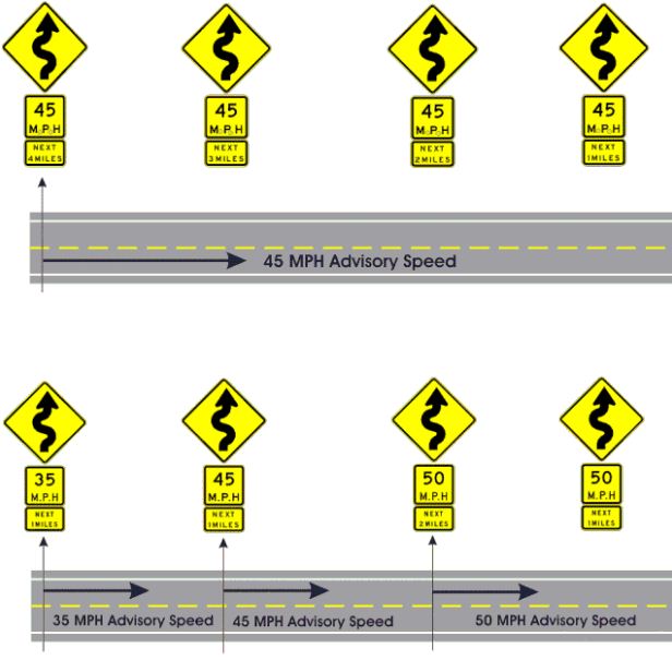
A NEXT XX MILES (W7-3aP) supplemental distance plaque may be installed below the Winding Road sign where continuous roadway curves exist for a specific distance.
903.6.7.4 Hairpin Curve (W1-11) and 270-Loop Signs (W1-15)
Option. If the curve has a change in horizontal alignment of 135 degrees or more, the Hairpin Curve (W1-11) sign may be used instead of a Curve or Turn sign.
If the curve has a change of direction of approximately 270 degrees, such as on a cloverleaf interchange ramp, the 270-degree Loop (W1-15) sign may be used instead of a Curve or Turn sign. Guidance. When the Hairpin Curve sign or the 270-degree Loop sign is installed, either a One-Direction Large Arrow (W1-6) sign or Chevron Alignment (W1-8) signs should be installed on the outside of the turn or curve.
903.6.7.5 Double Reverse Curve Left Sign (W24-1L) – Diverging Diamond Interchange (DDI) Application
Standard. A double reverse curve left sign (W24-1L) shall be used on the crossroad approachs to a DDI when the difference between the speed limit and advisory speed for the DDI is 5 mph or greater.
903.6.7.6 ALL LANES Supplemental Plaque (W24-1cP) – Diverging Diamond Interchange (DDI) Application
Standard. An ALL LANES supplemental plaque (W24-1cP) shall be placed below the double reverse curve left sign (W24-1L) for a diverging diamond interchange when there are two or more lanes in the direction the sign references.
Table 903.6.7 Horizontal Alignment Sign Usage
| Number of Alignment Changes | Advisory Speed | |
|---|---|---|
| Less than or equal to 30 mph | Greater than 30 mph | |
| 1 | Turn (W1-1)1 | Curve (W1-2)1 |
| 22 | Reverse Turn (W1-3)3 | Reverse Curve (W1-4)3 |
| 3 or more2 | Winding Road (W1-5)3 | |
| Notes:
1 Engineering judgment should be used to determine whether the Turn or Curve sign should be used. 2 Alignment changes are in opposite directions and are separated by a tangent distance of 600 ft. or less. 3 A Right Reverse Turn (W1-3R), Right Reverse Curve (W1-4R) or Right Winding (W1-5R) sign is used if the first change in aligment is the right; a Left Reverse Turn (W1-3L), Left Reverse Curve (W1-4L) or Left Winding (W1-5L) sign is used if the first change in aligment is the left. | ||
903.6.8 Combination Horizontal Alignment/Advisory Speed Sign (W1-1a, W1-2a) (MUTCD Section 2C.10)
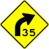
Option. The Turn (W1-1) sign or the Curve (W1-2) sign may be combined with the Advisory Speed (W13-1P) plaque (see EPG 903.6.45) to create a combination Turn/Advisory Speed (W1-1a) sign, or combination Curve/Advisory Speed (W1-2a) sign.
The combination Horizontal Alignment/Advisory Speed sign may be used to supplement the advance Horizontal Alignment warning sign and Advisory Speed plaque based upon an engineering study.
Standard. If used, the combination Horizontal Alignment/Advisory Speed sign shall not be used alone and shall not be used as a substitute for a Horizontal Alignment warning sign and Advisory Speed sign shall only be used as a supplement to the advance Horizontal Alignment warning sign. If used, the combination Horizontal Alignment/Advisory Speed sign shall be installed at the beginning of the turn or curve and the speed displayed shall match the advisory speed below the Horizontal Alignment sign.
Guidance. If used, the advisory speed displayed on the combination Horizontal Alignment/Advisory Speed sign should be based on the advisory speed for the horizontal curve using recommended engineering practices.
903.6.9 Combination Horizontal Alignment/Intersection Signs (W1-10 Series) (MUTCD Section 2C.11)
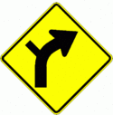
Option. The Turn (W1-1) sign or the Curve (W1-2) sign may be combined with the Cross Road (W2-1) sign or the Side Road (W2-2 or W2-3) sign to create a combination Horizontal Alignment/Intersection (W1-10 series) sign that depicts the condition where an intersection occurs within or immediately adjacent to a turn or curve.
Guidance. Elements of the combination Horizontal Alignment/Intersection sign related to horizontal alignment should comply with the provisions of EPG 903.6.7, Horizontal Alignment Sign, and elements related to intersection configuration should comply with the provisions of EPG 903.6.37 Intersection Warning Signs. The symbol design should approximate the configuration of the intersecting roadway(s). No more than one Cross Road or two Side Road symbols should be displayed on any one combination Horizontal Alignment/Intersection sign.
A layout of the proposed sign should be included when ordering.
Standard. If used, a Curve/Sideroad Left (W1-10L) sign shall indicate a curve to the left, while a Curve/Sideroad Right (W1-10R) sign shall indicate a curve to the right.
903.6.10 One-Direction Large Arrow Sign (W1-6) (MUTCD Section 2C.12)
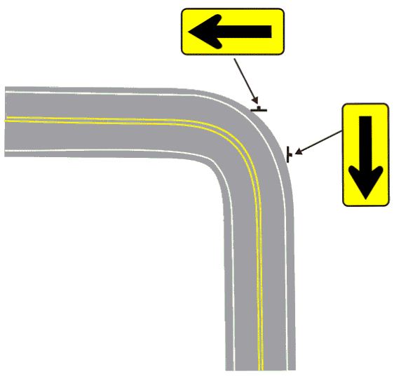
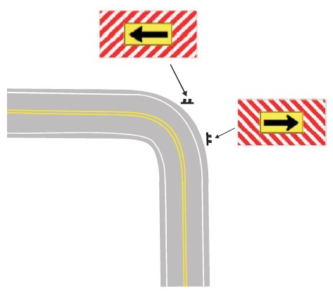
Option. A One-Direction Large Arrow (W1-6) sign may be used to either as a supplement or alternative to Chevron Alignment signs in order to delineate a change in horizontal alignment. A One-Direction Large Arrow (W1-6) sign may be used to supplement a Turn or Reverse Turn sign to emphasize the abrupt curvature (see Fig. 903.6.10).
Standard. The One-Direction Large Arrow sign shall be a horizontal rectangle with an arrow pointing to the left or right. The use of the One-Direction Large Arrow sign shall be in accordance with the information shown in Table 903.6.7. If used, the One-Direction Large Arrow sign shall be installed on the outside of a turn or curve in line with and at approximately a right angle to approaching traffic. The One-Direction Large Arrow sign shall not be used where there is no alignment change in the direction of travel, such as at the beginnings and ends of medians or at center piers. The One-Direction Large Arrow sign directing traffic to the right shall not be used in the central island of a roundabout.
Guidance. If used, the One-Direction Large Arrow sign should be visible for a sufficient distance to provide the road user with adequate time to react to the change in alignment. If chevrons are used, the One-Direction Large Arrow can replace a chevron. The One-Direction Large Arrow is not to be installed in front of a chevron.
Support. The One-Direction Large Arrow is generally used in conjunction with the Turn sign.
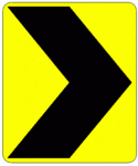
903.6.11 Chevron Alignment Sign (W1-8) (MUTCD Section 2C.09)
Standard. The use of the Chevron Alignment (W1-8) sign to provide additional emphasis and guidance for a change in horizontal alignment shall be used on roadways with more than 1,000 AADT.
Option. Chevron Alignment signs may also be used on other roadways with less than or equal to 1,000 AADT based on engineering judgment.
When used, Chevron Alignment signs may be used instead of or in addition to standard delineators on curves or to the One-Direction Large Arrow (W1-6) sign.
The single-sided Chevron sign side should be used where only one direction of travel is impacted, such as on an expressway.
The double-side Chevron (W1-8D) should be used on two-lane, two-way roads.
A Chevron Alignment sign may be used on the far side of an intersection to inform drivers of a change of horizontal alignment for through traffic.
Standard. The Chevron Alignment sign shall be a vertical rectangle. No border shall be used on the Chevron Alignment sign. If used, Chevron Alignment signs shall be installed on the outside of a turn or curve, in line with and at approximately a right angle to approaching traffic. Chevron Alignment signs shall be installed at a minimum height of 4 ft., measured vertically from the bottom of the sign to the elevation of the near edge of the traveled way.
This will place the sign at approximately the driver’s eye height.
Guidance. The approximate spacing of Chevron Alignment signs on the turn or curve measured from the point of curvature (PC) should be as shown in Table 903.6.11. If used, Chevron Alignment signs should be visible for a sufficient distance to provide the road user with adequate time to react to the change in alignment. In addition to the Chevron Alignment signs placed throughout the curve, there shall be one sign in advance of the PC and one after the PT. These signs shall be spaced the same as the Chevron Alignment signs in the curve.
Table 903.6.11 should be used for determining spacing. The values in Table 903.6.11 are typical and variances for driveways, public roads and other signs may alter the spacing. Engineering judgment may also be used to modify the spacing as long as travelers always have at least two Chevron Alignment signs in view until the change in alignment eliminates the need for the signs.
At the end of a divided highway, where the traffic reduces to two lanes, chevrons should be used to direct traffic from the dual lanes that are ending and being redirected to the two-lane roadway.
Support. Examples of when to use Chevron signs include locations where there is a crash history, evidence of drivers losing control on a curve or turn, a sharp change in alignment not readily visible to the driver, or as a systemic curve improvement program.
Standard. On qualifying roadways, Chevron Alignment signs shall be placed on all curves where the there is a 15 mph or more difference between the posted speed limit and the advisory speed for that curve. Turns that have an advisory speed posted at or below 30 mph shall have an arrow board, except as provided by the option above; see EPG 903.6.10 One-Direction Large Arrow Sign.
The installation of Chevron Alignment signs on qualifying roadways shall be completed by December 31, 2019.
Chevron Alignment signs shall not be placed on the far side of a T-intersection facing traffic on the stem approach to warn drivers that a through movement is not physically possible, as this is the function of a Two-Direction (or One-Direction) Large Arrow sign. Chevron Alignment signs shall not be used to mark obstructions within or adjacent to the roadway, including the beginning of guardrails or barriers, as this is the function of an object marker.
Table 903.6.11 Typical Spacing of Chevron Alignment Signs on Horizontal Curves
| Advisory Speed | Sign Spacing |
|---|---|
| 15 mph or less | 40 feet |
| 20 to 30 mph | 60 feet |
| 35 to 45 mph | 80 feet |
| 50 to 60 mph | 100 feet |
| More than 60 mph | 140 feet |
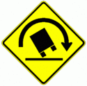
903.6.12 Truck Rollover Warning Sign (W1-13) (MUTCD Section 2C.13)
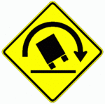
Option. A Truck Rollover Warning (W1-13) sign may be used to warn drivers of vehicles with a high center of gravity, such as trucks, tankers and recreational vehicles of a curve or turn where geometric conditions might contribute to a loss of control and a rollover as determined by an engineering study.
Standard. If a Truck Rollover Warning (W1-13) sign is used, an Advisory Speed Plaque (W13-1P) plaque indicating the recommended speed for vehicles with a higher center of gravity shall accompany it.
Option. The Truck Rollover Warning sign may be displayed as a static sign, as a static sign supplemented by a flashing warning beacon, or as a changeable message sign activated by the detection of an approaching vehicle with a high center of gravity that is traveling in excess of the recommended speed for the condition.
The curved arrow on the Truck Rollover Warning sign shows the direction of roadway curvature. The truck tips in the opposite direction.
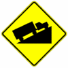
903.6.13 Hill Signs (W7-1) (MUTCD Section 2C.16)
Guidance. The Hill (W7-1) sign should be used in advance of a downgrade where the length, percent of grade, horizontal curvature and/or other physical features requires special precautions on the part of road users.
The Hill sign and supplemental grade (W7-3P) plaque (refer to EPG 903.6.14) used in combination should be installed in advance of downgrades for the following conditions:
A. 5% grade that is more than 3,000 ft. long;
B. 6% grade that is more than 2,000 ft. long;
C. 7% grade that is more than 1,000 ft. long;
D. 8% grade that is more than 750 ft. long;
E. 9% grade that is more than 500 ft. long;
F. 11% grade that is more than 400 ft. long;
G. 13% grade that is more than 300 ft. long;
H. 15% grade that is more than 200 ft. long; or
I. 16% or more grade that is any length.
These signs are also to be installed for steeper grades or where crash experience and field observations indicate a need or at grades of five percent or more where any part of the grade is on a curve sharper than four degrees.
Supplemental plaques (refer to EPG 903.6.14, below) and larger signs should be used for emphasis or where special hill characteristics exist. On longer grades, the use of the Hill sign with a distance (W7-3aP) plaque at periodic intervals of approximately 1 mile spacing should be considered.
Standard. If the percent grade is displayed on a supplemental plaque, the plaque shall be placed below the Hill (W7-1) sign.
Support. The Uphill (W7-1c) sign is also available by special request.
903.6.14 Hill-Related Supplemental Plaques (W7-3 Series) (MUTCD Section 2C.57)
Guidance. Hill-Related (W7-3 series) supplemental plaques or other appropriate legends and larger signs should be used for emphasis or where special hill characteristics exist. On longer grades, the use of the supplemental distance plaque (W7-3aP) at periodic intervals of approximately 1 mile spacing should be considered.
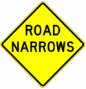
903.6.15 ROAD NARROWS Sign (W5-1) (MUTCD Section 2C.19)
Guidance. Except as provided below, a ROAD NARROWS (W5-1) sign should be used in advance of a transition on two-lane roads where the pavement width is reduced abruptly to such a narrow width that vehicles traveling in opposite direction cannot simultaneously travel through the narrow portion of the roadway without reducing speed.
Option. The ROAD NARROWS (W5-1) sign may be omitted on low-volume local streets that have speed limits of 30 mph or less. Additional emphasis may be provided by the use of object markers and delineators. The Advisory Speed (W13-1) plaque may be used to indicate the recommended speed.
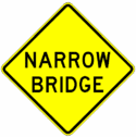
903.6.16 NARROW BRIDGE Sign (W5-2) (MUTCD Section 2C.20)
Guidance. A NARROW BRIDGE (W5-2) sign should be used in advance of any bridge or culvert having a two-way roadway clearance width of 16 ft. to 18 ft., or any bridge or culvert having a roadway narrower than the width of the approach travel lanes.
Additional emphasis should be provided by the use of object markers, delineators and/or pavement markings.
Option. A NARROW BRIDGE sign may be used in advance of a bridge or culvert on which the approach shoulders are narrowed or eliminated.
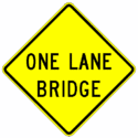
903.6.17 ONE LANE BRIDGE Sign (W5-3) (MUTCD Section 2C.21)
Guidance. A ONE LANE BRIDGE (W5-3) sign should be used on two-way roadways in advance of any bridge or culvert:
A. Having a clear roadway width of less than 16 ft.; or
B. Having a clear roadway width of less than 18 ft. when commercial vehicles constitute a high proportion of the traffic; or
C. Having a clear roadway width of 18 ft. or less where the sight distance is limited on the approach to the structure.
Additional emphasis should be provided by the use of object markers, delineators and/or pavement markings.
903.6.18 Divided Highway Sign (W6-1) (MUTCD Section 2C.22)
Guidance. A Divided Highway (W6-1) sign should be used on the approaches to a section of highway (not an intersection or junction) where the opposing flows of traffic are separated by a median or other physical barrier.
Standard. DIVIDED HIGHWAY supplemental plaque (W6-1c) has been discontinued. MoDOT shall no longer provide DIVIDED HIGHWAY supplemental plaque (W6-1c). Existing DIVIDED HIGHWAY supplemental plaque (W6-1c) shall be left in place until they reach the end of their service The Divided Highway (W6-1) sign shall not be used instead of a Keep Right (R4-7 series) sign on the approach end of a median island.
903.6.19 Divided Highway Ends Sign (W6-2) (MUTCD Section 2C.23)
Guidance. A Divided Highway Ends (W6-2) sign should be used in advance of the end of a section of physically divided highway (not an intersection or junction) as a warning of two-way traffic ahead.
Standard. DIVIDED HIGHWAY ENDS supplemental plaque (W6-2c) has been discontinued. MoDOT shall no longer provide DIVIDED HIGHWAY ENDS supplemental plaque (W6-2c). Existing DIVIDED HIGHWAY ENDS supplemental plaque (W6-2c) shall be left in place until they reach the end of their service life.
903.6.20 Double Arrow Sign (W12-1) (MUTCD Section 2C.25)
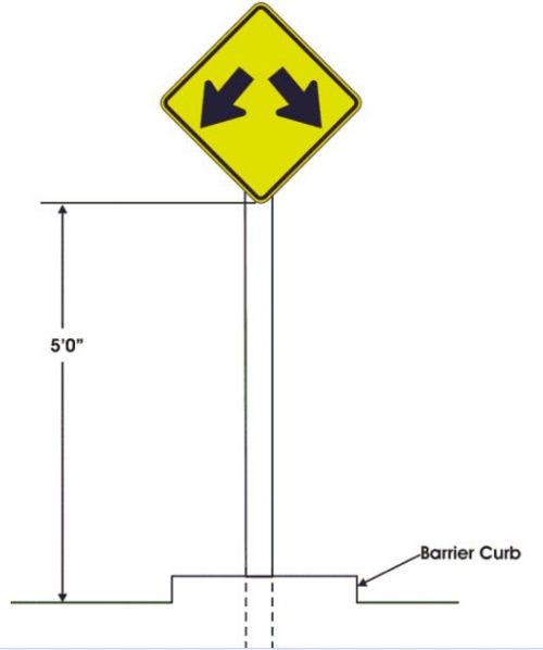
Option. The Double Arrow (W12-1) sign may be used to advise road users that traffic is permitted to pass on either side of an island, obstruction, or gore in the roadway (see Fig. 903.6.20). Traffic separated by this sign may either rejoin or change directions.
Guidance. If used on an island, the Double Arrow sign should be mounted near the approach end. If used in front of a pier or obstruction, the Double Arrow sign should be mounted on the face of, or just in front of, the obstruction. Where stripe markings are used on the obstruction, they should be discontinued to leave a 3 in. space around the outside of the sign.
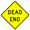
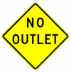
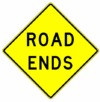
903.6.21 DEAD END, NO OUTLET and ROAD ENDS Signs (W14-1, W14-2, W14-13) (MUTCD Section 2C.26)
Option. The DEAD END (W14-1) sign may be used at the entrance of a single road or street that terminates in a dead end or cul-de-sac. The NO OUTLET (W14-2) sign may be used at the entrance to a road or road network from which there is no other exit in place of the DEAD END sign.
The ROAD ENDS (W14-13) sign may be used to warn of a roadway which has no outlet and which terminates in a dead end and may be used in place of the DEAD END or NO OUTLET sign where the used of the DEAD END and NO OUTLET signs would have a negative effect on traffic generators or public perceptions due to the negative connotation of the message.
Standard. When the W14-1, W14-2 or W14-13 sign is used, the sign shall be posted as near as practical to the entry point or at a sufficient advance distance to permit the road user to avoid the dead end or no outlet condition by turning off at the nearest intersecting street.
The DEAD END sign shall be placed at the appropriate distance from the end of the roadway.
The W14-2 or W14-13 sign shall not be used in place of the DEAD END sign at the end of the roadway.
The DEAD END sign shall be installed at the end of any state route that physically ends or ends at a private entrance.
The W14-1, W14-2 or W14-13 sign shall not be used in place of the ROAD CLOSED (R11-2) sign for temporary conditions, such as high water, bridge out, etc.
Guidance. The W14-1, W14-2 or W14-13 sign should be installed just beyond the entrance to all state maintained roadways where this condition exists.
903.6.22 Low Clearance Sign (W12-2 and W12-2a) (MUTCD Section 2C.27)
Standard. Low Clearance signing shall be installed to display vertical clearances available under structures within specified limits of statutory maximum vehicle heights. The clearance posted on the signs shall be 2 in. less than the measured clearance to account for possible packed snow and ice, for example, a measured vertical clearance of 15 ft. shall be posted as 14 ft. 10 in. All clearance measurements shall be rounded down to the nearest full inch, for example, a measured vertical clearance of 14 ft. 9 ½ in. would be rounded down to 14 ft. 9 in. and posted as 14 ft. 7 in. The statutory maximum vehicle heights and vertical clearances are as follows:
- Within Commercial Zones = 15 ft. statutory maximum vehicle height (16’ 0” maximum posting)
- On Interstate and designated highway network routes and on all routes within 10 miles of Interstate and designated highway network routes = 14 ft. statutory maximum vehicle height (15’ 0” maximum posting)
- On routes greater than 10 miles from Interstate and designated highway network routes = 13 ft. 6 in. statutory maximum vehicle height (15’ 0” maximum posting).
For specific details on commercial zone limits and designated highway network routes, see Missouri Vehicle Route Map (map inset).
Posting requirements for Low Clearance signs are as follows:
- Case I – Two Signs Required: Where the measured vertical clearance is 15 ft. 2 in. or less, but more than 13 ft. 8 in., two signs shall be used. First, the clearance shall be posted on the structure by an Overhead Low Clearance (W12-2a) sign and, second, a shoulder mounted Low Clearance (W12-2) sign shall be placed approximately 750 ft. in advance of the structure. When an interchange is involved, the shoulder-mounted Low Clearance (W12-2) sign shall be located approximately 750 ft. in advance of the off-ramp. The maximum vertical clearance shown on the signs under these conditions shall be 15 feet.
- Case II – Three Signs: Where the measured vertical clearance is 13 ft. 8 in. or less, three signs shall be used. First, the clearance shall be posted on the structure by an Overhead Low Clearance (W12-2a) sign, second, a shoulder mounted Low Clearance (W12-2) sign shall be placed approximately 750 ft. in advance of the structure, and third, an additional Low Clearance (W12-2) sign shall be placed at the nearest intersecting road or wide point in the road at which a vehicle can detour or turn around. The maximum height shown on the signs under these conditions shall be 13 ft. 6 inches.
- Case III – One Sign: Where the measured vertical clearance is 15 ft. 2 in. or less and where the bridge is state maintained but the road beneath is not, the Overhead Low Clearance (W12-2a) sign shall be mounted on the structure, but the shoulder mounted Low Clearance (W12-2) sign shall not be installed by MoDOT, but may be installed and maintained by the local jurisdiction.
- Case IV – Commercial Zones: Vertical clearance signing shall be provided for structures within commercial zones (see Missouri Statute 304.190). Any structure with a measured vertical clearance of 16 ft. 2 in. or less within the commercial zone limits shall be posted. The signing for measured vertical clearances greater than 15 ft. 2 in. and equal to or less than 16 ft. 2 in. within commercial zones shall be posted on the structure by an Overhead Low Clearance (W12-2a) sign. The signing for measured vertical clearances of 15 ft. 2 in. or less within commercial zones shall be the same as Case I and Case III.
Standard. The Overhead Low Clearance (W12-2a) sign should be mounted on a structure centered over the lane or lanes affected. The vertical clearance displayed on the sign shall represent the smallest vertical clearance for that span.
In the case of an arch structure or a structure which has a sloping span resulting in different vertical clearances per lane, one Overhead Low Clearance (W12-2a) sign shall be centered over each lane displaying the vertical clearance available for that lane. One sign per lane shall be applied if the difference in vertical clearance between adjacent lanes is 6 inches or greater or when the vertical clearance between the far right lane and far left lane is 12 inches or greater.
Option. When only one Overhead Low Clearance (W12-2a) sign is required and mounting one sign centered over the roadway is not practical the W12-2a sign may be double posted with one sign mounted to the right of the travel lanes and one sign mounted to the left of the travel lanes.
Guidance. Clearances should be evaluated periodically, particularly when resurfacing operations have occurred, to assure the displayed clearances are accurate and the information should be updated in TMS.
Standard. Low Clearance (W2-12b) sign has been discontinued. MoDOT shall no longer provide Low Clearance (W2-12b) signs. Existing Low Clearance (W2-12b) sign shall be left in place until they reach the end of their service life.
903.6.23 BUMP and DIP Signs (W8-1, W8-2) (MUTCD Section 2C.28)
Standard. The BUMP and DIP warning signs (W8-1, W8-2) have been discontinued. Existing BUMP and DIP signs (W8-1, W8-2) shall be left in place until the pavement condition is corrected. BUMP and DIP signs will be available as temporary traffic control signs (WO8-1, WO8-2). Guidance can be found in EPG 616 Temporary Traffic Control.
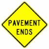
903.6.24 PAVEMENT ENDS Sign (W8-3) (MUTCD Section 2C.30)
Guidance. A PAVEMENT ENDS (W8-3) word message sign should be used where a paved surface changes to either a gravel treated surface or an earth road surface.
903.6.25 SOFT SHOULDER Sign (W8-4) (MUTCD Section 2C.31)
Option. The SOFT SHOULDER (W8-4) sign may be used to warn of a soft shoulder condition.
Guidance. Additional shoulder signs should be placed at appropriate intervals along the road where the condition continually exists.
Standard. When used, SOFT SHOULDER sign shall be placed in advance of the condition. See Table 903.6.6.
903.6.26 Slippery When Wet Sign (W8-5) (MUTCD Section 2C.32)
Standard. Slippery When Wet Warning (W8-5) signs have been discontinued. Existing Slippery When Wet (W8-5) signs shall be left in place until the condition is corrected. Once the condition is corrected, the sign shall then be removed. Slippery When Wet Temporary Traffic Control signs (WO8-5) will be available to warn of this condition temporarily until the condition can be corrected. Guidance can be found in EPG 616 Temporary Traffic Control.
903.6.27 FALLEN ROCKS Sign (W8-14) (MUTCD Section 2C.32)
Option. The FALLEN ROCKS (W8-14) sign may be used to warn motorist where falling rocks may be on the roadway.
Standard. The district shall perform an evaluation of the Fallen Rocks site to determine whether this sign is still necessary. If it is determined that Fallen Rocks is not an issue at the site, the sign will not be replaced at the end of the service life.
903.6.28 Advance Traffic Control Signs (W3-1, W3-2, W3-3, W3-4) (MUTCD Section 2C.36)
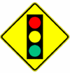
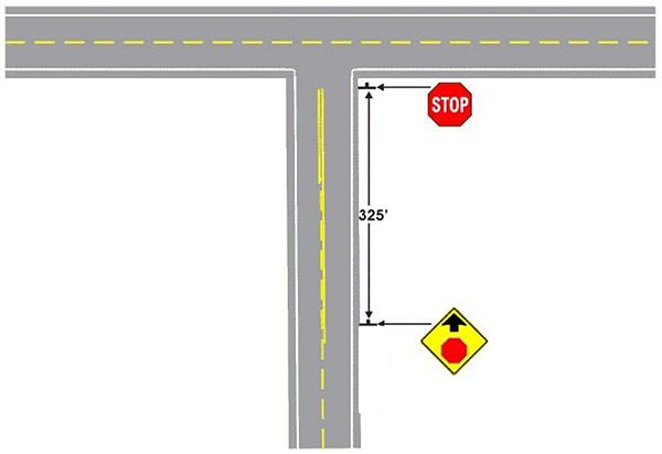
Standard. The Advance Traffic Control symbol signs include the Stop Ahead (W3-1), Yield Ahead (W3-2), and Signal Ahead (W3-3) signs. These signs shall be installed on an approach to a primary traffic control device that is not visible for a sufficient distance to permit the road user to respond to the device. The visibility criteria for a traffic control signal shall be based on having a continuous view of at least two signal faces for the distance specified in Table 903.6.28. The criteria for the STOP AHEAD (W3-1) and YIELD AHEAD (W3-2) are specified in Table 903.6.6. (See Fig. 903.6.28 for an example application.)
Support. Permanent obstructions causing the limited visibility might include roadway alignment or structures. Intermittent obstructions might include foliage or parked vehicles.
Guidance. Where intermittent obstructions occur, engineering judgment should determine the treatment to be implemented.
The minimum visibility distance of a signal for a facility with a speed limit above 60 mph should be determined by summing the stopping sight distance (see Table 903.6.5) and the assumed queue length. The assumed queue length should be determined by engineering judgment.
If an advance traffic control sign is warranted for an approach at an intersection of a MoDOT maintained road and non-MoDOT maintained road, the maintainer of the non-MoDOT road should be notified of the condition.
Option. An Advance Traffic Control sign may be used for additional emphasis of the primary traffic control device, even when the visibility distance to the device is satisfactory. An advance street name plaque (refer to EPG 903.6.48) may be installed below an Advance Traffic Control sign.
The Signal Ahead (W3-3) signs may be double posted on the right-hand and left-hand shoulders on a high speed divided approach.
A warning beacon may be used with an Advance Traffic Control sign.
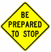
A BE PREPARED TO STOP (W3-4) sign may be used to warn of stopped traffic caused by a traffic control signal or in advance of a section of roadway that regularly experiences traffic congestion.
Table 903.6.28 Requirements for Advance Traffic Control Sign Placements
| 85th Percentile Speed (mph) | Minimum Visibility Distance (ft.) |
|---|---|
| 20 | 175 |
| 25 | 215 |
| 30 | 270 |
| 35 | 325 |
| 40 | 390 |
| 45 | 460 |
| 50 | 540 |
| 55 | 625 |
| 60 | 715 |
| Note: Distances in this table are derived from stopping sight distance plus an assumed queue length for shorter cycle lengths (60 to 75 seconds). | |
Standard. When a BE PREPARED TO STOP (W3-4) sign is used in advance of a traffic control signal, it shall be used in addition to a Signal Ahead (W3-3) sign and shall be placed downstream from the Signal Ahead (W3-3) sign.
Option. The BE PREPARED TO STOP (W3-4) sign may be supplemented with a warning beacon.
Guidance. When the warning beacon is interconnected with a traffic control signal or queue detection system, the BE PREPARED TO STOP sign should be supplemented with a WHEN FLASHING (W16-13P) plaque.
903.6.29 Advance Ramp Control Signal Signs (W3-7 and W3-8) (MUTCD Section 2C.37)
Option. A RAMP METER AHEAD (W3-7) sign may be used to warn road users that a freeway entrance ramp is metered and that they will encounter a ramp control signal.
Guidance. When the ramp control signals are operated only during certain periods of the day, a RAMP METERED WHEN FLASHING (W3-8) sign should be installed in advance of the ramp control signal near the entrance to the ramp, or on the arterial on the approach to the ramp, to alert road users to the presence and operation of ramp meters.
Standard. The RAMP METERED WHEN FLASHING sign shall be supplemented with a warning beacon that flashes when the ramp control signal is in operation.
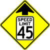
903.6.30 Reduced Speed Limit Ahead Signs (W3-5) (MUTCD Section 2C.38)
Guidance. A Reduced Speed Limit Ahead (W3-5) sign should be used to inform road users of a reduced speed zone where the speed limit is being reduced by more than 10 mph or where engineering judgment indicates the need for advance notice to comply with the posted speed limit ahead.
Standard. If used, Reduced Speed Limit Ahead signs shall be followed by a Speed Limit (R2-1) sign installed at the beginning of the zone where the speed limit applies.
The speed limit displayed on the Reduced Speed Limit Ahead sign shall be identical to the speed limit displayed on the subsequent Speed Limit sign.
Speed Reduction signs shall be installed in advance of a speed reduction of 15 mph or greater from the posted speed limit.
903.6.31 Merge Signs (W4-1, W4-5) (MUTCD Section 2C.40)
Guidance. The Merge sign should be installed on the side of the major roadway where merging traffic will be encountered and in such a position as to not obstruct the road user’s view of entering traffic. Where two roadways of approximately equal importance converge, a Merge sign should be placed on each roadway. When a Merge sign is to be installed on an entering roadway that curves before merging with the major roadway, such as a ramp with a curving horizontal alignment as it approaches the major roadway, the Entering Roadway Merge (W4-5) sign should be used to better portray the actual geometric conditions to road users on the entering roadway. The Merge sign should not be used where two roadways converge and merging movements are not required. The Merge sign should not be used in place of a Lane Ends sign where lanes of traffic moving on a single roadway must merge because of a reduction in the actual or usable pavement width.
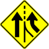
903.6.32 Added Lane Signs (W4-3, W4-6) (MUTCD Section 2C.41)
Guidance. The Added Lane (W4-3) sign should be installed in advance of a point where two roadways converge and merging movements are not required. When possible, the Added Lane sign should be placed such that it is visible from both roadways; if this is not possible, an Added Lane sign should be placed on the side of each roadway.
When an Added Lane sign should be installed on a roadway that curves before converging with another roadway that has a tangent alignment at the point of convergence, the Entering Roadway Added Lane (W4-6) sign should be used to better portray the actual geometric conditions to road users on the curving roadway.
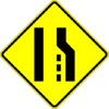
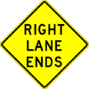
903.6.33 LANE END Signs (W4-2, W9-1, W9-2) (MUTCD Section 2C.42)
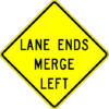
Guidance. The LANE ENDS MERGE LEFT (RIGHT) (W9-2) sign or the Lane Ends (W4-2) sign should be used to warn of the reduction in the number of traffic lanes in the direction of travel on a multi-lane highway.
Option. The RIGHT (LEFT) LANE ENDS (W9-1) sign may be used in advance of the Lane Ends (W4-2) sign or the LANE ENDS MERGE LEFT (RIGHT) (W9-2) sign as additional warning or to emphasize that the traffic lane is ending and that a merging maneuver will be required.
On one-way streets or on divided highways where the width of the median will permit, two Lane Ends (W4-2) signs may be placed facing approaching traffic; one on the right-hand side and the other on the left-hand side or median.
Support. EPG 620.2.9 Lane Reduction Transition Markings contains information regarding the use of pavement markings in conjunction with a lane reduction.
Guidance. Where an extra lane has been provided for slower moving traffic (see SLOWER TRAFFIC KEEP RIGHT Sign), a Lane Ends (W9-2) word sign or a Lane Ends (W4-2) symbol sign should be installed in advance of the downstream end of the extra lane.
Lane Ends signs should not be installed in advance of the downstream end of an acceleration lane of an interchange on ramp.
Standard. In dropped lane situations, regulatory signs (see EPG 903.5.12) shall be used to inform road users that a through lane is becoming a mandatory turn lane. The W4-2, W9-1 and W9-2 signs shall not be used in dropped lane situations.
903.6.34 Two-Way Traffic Sign (W6-3, W16-9P) (MUTCD Section 2C.44)
Guidance. A Two-Way Traffic (W6-3) sign should be used to warn road users of a transition from a multi-lane divided section of roadway to a two-lane, two-way section of roadway.
A Two-Way Traffic (W6-3) sign with an AHEAD (W16-9P) plaque should be used to warn road users of a transition from a one-way street to a two-lane, two-way section of roadway.
Option. The Two-Way Traffic sign may be used at intervals along a two-lane, two-way roadway and may be used to supplement the Divided Highway Ends (W6-2) sign discussed in EPG 903.6.19.
Standard. The TWO WAY TRAFFIC supplemental plaque (W6-3c) has been discontinued. MoDOT shall no longer provide TWO WAY TRAFFIC supplemental plaques (W6-3c). Existing TWO WAY TRAFFIC supplemental plaques (W6-3c) shall be left in place until they reach the end of their service life.
903.6.35 NO PASSING ZONE Sign (W14-3) (MUTCD Section 2C.45)
Support. The NO PASSING ZONE (W14-3) sign is not to be used on a system-wide basis. It is intended for special use at locations where passing crashes are present and as a measure to correct those accidents.
Standard. The NO PASSING ZONE (W14-3) sign shall be a pennant-shaped isosceles triangle with its longer axis horizontal and pointing to the right. When used, the NO PASSING ZONE sign shall be installed on the left side of the roadway at the beginning of no-passing zones identified by pavement markings or DO NOT PASS (R4-1) signs or both (see EPG 903.5.16).
The use of the NO PASSING ZONE sign shall be approved by the State Traffic Engineer.
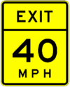
903.6.36 Advisory Exit and Ramp Speed Signs (W13-2 and W13-3) (MUTCD Section 2C.14)
Standard. Advisory Exit Speed (W13-2) and Advisory Ramp Speed (W13-3) signs shall be vertical rectangles. The use of Advisory Ramp Speed sign shall be approval by the State Traffic Engineer.
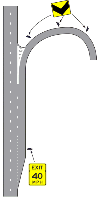
Guidance. If used, the Advisory Exit Speed sign should be installed along the deceleration lane and the advisory speed displayed should be based on an engineering study. When a Truck Rollover (W1-13) sign (see EPG 903.6.12) is also installed for the ramp, the advisory exit speed should be based on the truck advisory speed for the horizontal alignment using recommended engineering practices. If used, the Advisory Exit Speed sign should be visible in time for the road user to decelerate and make an exiting maneuver.
Guidance. If used, the Advisory Ramp Speed sign should be installed on the ramp to confirm the ramp advisory speed.
Option. Where there is a need to remind road users of the recommended advisory speed, a horizontal alignment warning sign with an advisory speed plaque may be installed at or beyond the beginning of the exit curve or on the outside of the curve, provided that it is apparent that the sign applies only to exiting traffic. These signs may also be used at intermediate points along the ramp, especially if the ramp curvature changes and the subsequent curve on the ramp have a different advisory speed than the initial ramp curve.
903.6.37 Intersection Warning Signs (W2-1 through W2-8) (MUTCD Section 2C.46)
Support. Intersection Warning Signs are used when there is limited sight distance, crashes, or based on engineering judgment.
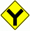
Option. A Crossroad (W2-1) symbol, Side Road (W2-2 or W2-3) symbol, T-Symbol (W2-4), or Y-Symbol (W2-5) sign may be used in advance of an intersection to indicate the presence of an intersection and the possibility of turning or entering traffic.
Intersection Warning signs may be used with Advance Traffic Control signs, but not replace the Advance Traffic Control sign.
The relative importance of the intersecting roadways may be shown by different widths of lines in the symbol.
An Advance Street Name plaque (see EPG 903.6.48) may be installed above or below an Intersection Warning sign.
Guidance. The Intersection Warning sign should illustrate and depict the general configuration of the intersecting roadway, such as crossroad, side road, T-intersection, or Y-intersection.
Where the side roads are not opposite each other, the symbol for the intersection should indicate a slight offset.
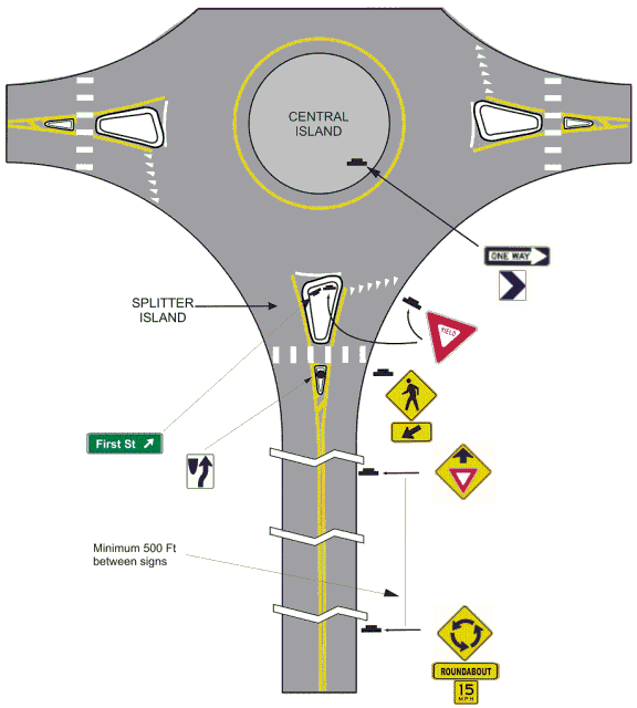
Roundabout Warning Signs (W2-6 and W16-17P)
Standard. The Circular Intersection sign shall be installed in advance of any roundabout intersection. The ROUNDABOUT (W16-17P) plaque along with the appropriate Advisory Speed supplemental plaque (W13-1P) shall be installed below the Circular Intersection sign.
Option. If other circular intersections exist, that would not be classified a roundabout, the Circular Intersection (W2-6) sign may be used.
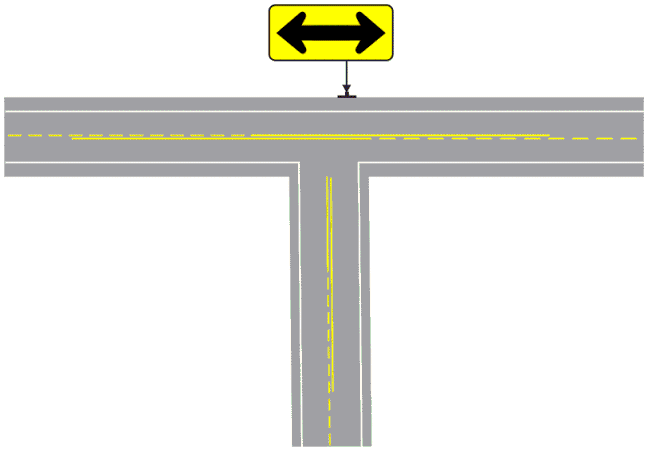
903.6.38 Two-Direction Large Arrow Sign (W1-7) (MUTCD Section 2C.47)
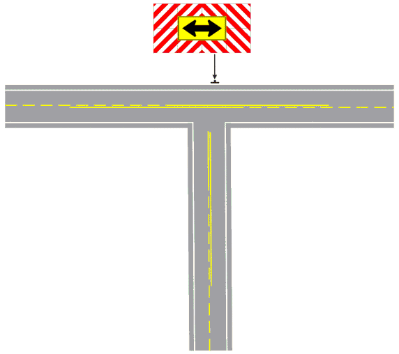
Standard. The Two-Direction Large Arrow (W1-7) sign shall be a horizontal rectangle. If used, it shall be installed on the far side of a T-Intersection in line with, and at approximately a right angle to, traffic approaching from the stem of the T-intersection (see Figure 903.6.38).
The Two-Direction Large Arrow sign shall not be used where there is no change in the direction of travel such as at the beginnings and ends of medians or at center piers.
The Two-Direction Large Arrow sign directing traffic to the left and right shall not be used in the central island of a roundabout.
Guidance. The Two-Direction Large Arrow sign should be visible for a sufficient distance to provide the road user with adequate time to react to the intersection configuration.
903.6.39 Traffic Signal Signs (W25-1, W25-2) (MUTCD Section 2C.48)
Support. If a left turn trap exists a Traffic Signal sign is needed, unless the signal has a permissive left that is tied to the opposing through (i.e. Dallas phasing).
Standard. At locations where either a W25-1 or a W25-2 sign is required based on the provisions in EPG 902.5.11 Application of Steady Signal Indications, the W25-1 or W25-2 sign shall be installed near the left-most signal head. The W25-1 and W25-2 signs shall be vertical rectangles.
903.6.40 Vehicular Traffic Warning Signs (W11-1, W11-1b, W11-5, W11-8, W11-10, W11-12P, W11-14) (MUTCD Section 2C.49)
Option. Vehicular Traffic Warning (W11-1, W11-5, W11-8, W11-10, W11-12P, W11-14) signs may be used to alert road users to locations where unexpected entries into the roadway by trucks, bicyclists, farm vehicles, emergency vehicles, horse-drawn vehicles or other vehicles might occur.
Support. These locations may be relatively confined or occur randomly over a roadway segment.
Guidance. Vehicular Traffic Warning signs should be used only at locations where the road user’s sight distance is restricted, or the condition, activity or entering traffic would be unexpected. If the condition or activity is seasonal or temporary, the Vehicular Traffic Warning sign should be removed or covered when the condition or activity does not exist.
Haul routes that are sporadic should use the portable or turnable Truck Crossing installations and have a Contract for Signs at Truck Crossings (TR12), found on p:contract/tr, executed.
When the HORSE DRAWN VEHICLE sign (W11-14) or the BICYLE sign (W11-1) is used to notify motorist of these vehicles traveling along a roadway, the Share the Road supplemental plaque (W16-1P) should be installed below the sign and be repeated in accordance with the Share the Road sign guidance.
Option. Supplemental Warning plaques (refer to EPG 903.6.42) with legends such as AHEAD (W16-9P), XX FEET or NEXT XX MILES may be mounted below Vehicular Traffic signs to provide advance notice to road users of unexpected entries.
Standard. For an entrance to be eligible for “Emergency Vehicle Entrance” signing, the facility shall be adjacent and visible from the roadway, shall be recognizable as such and shall have direct access to the state roadway system. If the entrance is signalized, the Emergency Vehicle (W11-8) sign with the EMERGENCY SIGNAL AHEAD (W11-12P) supplemental plaque shall be placed in advance of all emergency-vehicle traffic control signals.
903.6.41 Non-Vehicular Warning Signs (W11-2, W11-3, W11-4, W11-7, W11-32, W11-33, W16-9P) (MUTCD Section 2C.50)
Option. Non-Vehicular Warning signs may be used to alert road users in advance of locations where unexpected entries into the roadway might occur or where shared use of the roadway by pedestrians, animals or equestrians might occur.
Support. The conflicts may be relatively confined or occur randomly over a roadway segment.
Standard. Equestrian (W11-7) Crossing signs should only be installed at Public Equestrian Trail Crossings. Existing Equestrian (W11-7) Crossing signs that do not meet the Public Equestrian Trail Crossing criteria, shall be left in place until they reach the end of their service life.
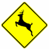
Deer (W11-3) and Goose (W11-32) Crossing signs shall only be approved for locations that, through an Engineering Study, as supported by historical data, accident reports or data collected by the Department of Conservation and the Department of Transportation on the number of animals killed at a given location. Any existing sign should be removed at the end of its life cycle unless installation is supported by the previous guidance.
The Pedestrian (W11-2) sign shall be used in advance of a marked pedestrian crossing. At a marked pedestrian crossing the Pedestrian sign and the Diagonal Downward Crossing Arrow (W16-7P) plaque shall be used, except at signalized and stop controlled intersections.
The Cattle (W11-4) sign shall be issued to an individual only when the Application for Sign at Cattle Crossings contract (TR9), found on P:\contract\TR, has been signed.
If a post-mounted W11-2 or W11-7 sign is placed at the location of the crossing point where pedestrians or equestrians might be crossing the roadway, a diagonal downward pointing arrow (W16-7P) plaque shall be mounted below the sign. If the W11-2 or W11-7 sign is mounted overhead, the W16-7P plaque shall not be used.
Guidance. Deer signs put up due to temporary flooding or development should be reevaluated when the condition stabilizes.
The district traffic engineering staff is to confirm the need for the Deer (W11-3) and Equestrian (W11-7) sign.
When used in advance of a pedestrian or equestrian crossing, the W11-2 or W11-7 sign should be supplemented with plaques (see EPG 903.6.46) with the legend AHEAD or XX FEET to inform road users that they are approaching a point where crossing activity might occur.
The crossing location may be defined with crosswalk markings (see EPG 620 Pavement Markings).
Guidance. The mixing of standard fluorescent yellow and fluorescent yellow-green backgrounds within a selected site area should be avoided.
903.6.42 FERRY CROSSING AHEAD Sign (W3-18)
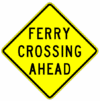
Option. The FERRY CROSSING AHEAD (W3-18) sign may be erected for a ferry crossing. A STOP (R1-1) sign at the ferry crossing may be used as a supplement.
903.6.43 Use of Supplemental Warning Plaques (MUTCD Section 2C.53)
Option. A supplemental warning plaque may be displayed with a warning or regulatory sign when engineering judgment indicates that road users require additional warning information beyond that contained in the main message of the warning or regulatory sign.
Standard. Supplemental warning plaques shall be used only in combination with warning or regulatory signs. They shall not be mounted alone or displayed alone. If used, a supplemental warning plaque shall be installed on the same post(s) as the warning or regulatory sign that it supplements.
Unless otherwise provided in this guidance for a particular plaque, supplemental warning plaques shall be mounted below the sign they supplement.
903.6.44 Design of Supplemental Warning Plaques (MUTCD Section 2C.54)
Standard. A supplemental warning plaque used with a warning sign shall have the same legend, border, and background color as the warning sign with which it is displayed. A supplemental warning plaque used with a regulatory sign shall have a black legend and border on a yellow background. Supplemental warning plaques shall be square or rectangular.
903.6.45 Distance Supplemental Plaques (W16-2 Series, W16-3 Series, W16-4P, W7-3aP) (MUTCD Section 2C.55)
Option. The Distance Ahead (W16-2 series and W16-3 series) supplemental plaques may be used to inform the road user of the distance to the condition indicated by the warning sign.
The Next Distance (W7-3aP and W16-4P) supplemental plaques may be used to inform road users of the length of roadway over which the condition indicated by the warning sign exists.
Standard. Distances shall be shown in ¼ mile or 100 ft. increments. If the distance is less than a ½ mile then feet shall be used.
903.6.46 Advisory Speed Supplemental Plaque (W13-1P) (MUTCD Section 2C.08)
Option. The Advisory Speed (W13-1P) plaque may be used to supplement any warning sign to indicate the advisory speed for a condition.
The Advisory Speed supplemental plaque may be used in conjunction with any standard warning sign.
| The procedure to determine the safe speed on a curve or turn is a ball bank study. To correctly use the ball bank indicator, the ball bank indicator should be mounted on the dashboard of a passenger car and adjusted to read "0" when the car is stationary on a level grade with the ball bank indicator being in a vertical plane. When adjusting the indicator, all personnel who are to be in the car while testing should be in their seats and all four tires should have the same pressure. It is usually best for at least two persons to be in the car while taking the ball bank reading: one for driving, the other for observation and recording. |
| The 10-degree reading that can be maintained the complete length of a curve is the appropriate safe speed for that curve. Care must be taken to maintain the car in its proper lane and to maintain a smooth even speed throughout the curve. It will occasionally be found that a curve will have a higher safe speed in one direction than the other. In such cases, the lower safe speed should be used for both directions. Only increments of 5 mph are used on the Advisory Speed Plaque, therefore the curve shall be posted to the nearest 5 mph speed from the survey. |
Standard. The Advisory Speed plaque shall be used where an engineering study indicates a need to advise road users of the advisory speed for other roadway conditions. The Advisory Speed plaque shall be used with all curve, turn and winding road signs where the curve(s) ballbank at least 5 mph below the posted speed. If the curve(s) ballbank at, or above, the posted speed limit, the advisory speed plaque is optional. If used, the Advisory Speed plaque shall carry the message XX MPH. The speed displayed shall be a multiple of 5 mph.
Except in emergencies or when the condition is temporary, an Advisory Speed plaque shall not be installed until the advisory speed has been determined by an engineering study. The Advisory Speed plaques shall never be mounted alone. The maximum advisory speed posted shall never be more than the posted speed limit. The Advisory Speed plaque shall only be used to supplement a warning sign and shall not be installed as a separate sign installation. The advisory speed shall be determined by an engineering study that follows established engineering practices.
Guidance. Because changes in conditions, such as roadway geometrics, surface characteristics, or sight distance, might affect the advisory speed, each location should be evaluated periodically or when conditions change.
Support. The Advisory Speed supplemental plaques are available in 5 mph increments.
903.6.47 Supplemental Arrow Plaque (W16-5P, W16-6P) (MUTCD Section 2C.56)
Guidance. If the condition indicated by a warning sign is located on an intersecting road and the distance between the intersection and condition is not sufficient to provide adequate advance placement of the warning sign, a Supplemental Arrow (W16-5P and W16-6P) plaque should be used below the warning sign.
Standard. Supplemental Arrow plaques shall have the same legend design as the Advance Turn Arrow and Directional Arrow auxiliary signs except that they shall have a black legend and border on a fluorescent yellow or fluorescent yellow-green background, as appropriate.
903.6.48 Advance Street Name Supplemental Plaque (W16-8P, W16-8aP) (MUTCD Section 2C.58)
Support. Advance street name signing can provide valuable information to the motorist. Intersections that are signed with Intersection Warning (W2 series) or Advance Traffic Control (W3 series) signs typically have inherent sight distance concerns. The addition of the street name to the warning sign can aid a motorist in making decisions in a timely manner.
Option. An Advance Street Name (W16-8P or W16-8aP) plaque may be used with any Intersection sign (W2 series) or Advance Traffic Control (W3 series) sign to identify the name of the intersecting street.
If the side road being signed is maintained by a public agency, the addition of the street name sign may be considered on request.
Guidance. Advance Street Name supplemental signs are only to be used with intersection or advance traffic control warning signs that are properly installed according to MoDOT guidelines.
Standard. The street name used on an Advance Street Name supplemental sign shall be the approved name used by either the local agency or the Emergency 911 Coordinator.
When used, the Advance Street Name supplemental plaque shall only be mounted below the W2 or W3 series warning sign or the Mileage Plaque on the same post. The Advance Street Name supplemental plaque for a 36 in. x 36 in. warning sign shall be a maximum of 36 in. wide and for a 48 in. x 48 in. warning sign shall be a maximum of 48 in. wide.
The lettering on Advance Street Name plaques shall be composed of a combination of lower-case letters with initial upper-case letters.
If two street names are used on the Advance Street Name plaque, a directional arrow pointing in the direction of the street shall be placed next to each street name. Arrows pointing to the left shall be placed to the left of the street name, and arrows pointing to the right shall be placed to the right of the street name.
903.6.49 CROSS TRAFFIC DOES NOT STOP Plaque (W4-4P) (MUTCD Section 2C.59)
Option. The CROSS TRAFFIC DOES NOT STOP (W4-4P) plaque may be used in combination with a STOP sign when engineering judgment indicates that conditions are present that are causing or could cause drivers to misinterpret the intersection as an all-way stop.
Standard. If a W4-4P plaque or a plaque with an alternate message is used, it shall be mounted below the STOP sign.
903.6.50 SHARE THE ROAD Supplemental Plaque (W16-1P) (MUTCD Section 2C.60)
Option. In situations where there is a need to warn drivers to watch for other slower forms of transportation traveling along the highway, such as bicycles or horse-drawn vehicles, a SHARE THE ROAD (W16-1P) plaque may be used.
Guidance. SHARE THE ROAD (W16-1P) plaques should be installed at a point where vehicles will first encounter slower forms of transportation.
Option. SHARE THE ROAD plaques may be installed after any major intersections where new traffic might enter the roadway.
Standard. A W16-1P plaque shall not be used alone. If a W16-1P plaque is used, it shall be mounted below either a BICYCLE (W11-1) or a HORSE DRAWN VEHCLE (W11-14) sign. The background color of the W16-1P plaque shall match the background color of the warning sign with which it is displayed.
903.6.51 PHOTO ENFORCED Plaque (W16-10aP) (MUTCD Section 2C.61)
Option. A PHOTO ENFORCED (W16-10aP) word message plaque may be mounted below a warning sign to advise road users that the regulations associated with the condition being warned about (such as a traffic control signal) are being enforced by photographic equipment.
Standard. If used below a warning sign, the PHOTO ENFORCED (W16-10aP) plaque shall be a rectangle with a black legend and border on a fluorescent yellow background.
903.6.52 IMPASSABLE DURING HIGH WATER Sign (W8-18, W8-19a, W8-34, W8-35) (MUTCD Section 2C.35)
Option. The IMPASSABLE DURING HIGH WATER (W18-34) sign may be used to warn of low water crossing, or section of highway where normal rainfall will cause water to be over the roadway, see EPG 616.23 Traffic Control For Field Operations. Where used, this sign may be a flip sign with the combination of a ROAD MAY FLOOD sign (W8-18).
The LOW WATER CROSSING (W8-35) may also be used to warn of low water crossings.
Standard. The Gauge Board (W8-19a) sign shall be used at all low water crossings as a supplement to the IMPASSABLE DURING HIGH WATER sign and shall indicate the depth of the water at the deepest point on the roadway.
903.6.53 Hazard Communication Signs
Support. Missouri's Community Right-to-Know law requires visible markings on the outside of buildings, rooms and containers where hazardous substances are present.
The NFPA 704 marking system uses a diamond-shaped sign (Exhibit D) that is divided into four smaller diamonds. The four smaller diamonds, which are 7½ in. square, are different colors (blue, red, yellow and white) with numbers or symbols that represent the hazards posed by the materials stored inside the building or room. The four quadrants of the sign indicate the potential hazards associated with health (blue), fire or flammability (red), reactivity (yellow) and special hazards (white). Special hazards (white) will not be indicated on our signing.
Table 903.6.53 contains information on these signs.
To verify correct marking contact the district safety officer or the Environmental Compliance Coordinator.
Standard. Hazard Communication signs shall conform to the National Fire Protection Association (NFPA) standard 704, except that containers may be marked to conform to the OSHA hazard communication standard.
Each highway facility where reportable quantities of hazardous materials are used or stored shall be visibly marked with a diamond-shaped sign conforming to the NFPA standard 704 marking system. The sign shall be mounted on the outside wall of each building or room next to the pedestrian door. If the pedestrian door is located on the end of the building, a second sign shall be mounted on the front outside wall near the center of the building.
Bulk striping paint storage docks and/or aboveground storage tanks shall be marked with a sign. Aboveground paint storage tanks shall have a sign (decal) mounted near the top of the tank on the side facing the drive or lot. A post-mounted sign shall be located at the front of paint storage docks in a spot, which is highly visible but not where it will interfere with the loading or unloading of paint.
Aboveground asphalt storage tanks shall have a sign (decal) mounted near the top of the tank on the end or side facing the drive or lot. If there is more than one tank at a single location, only one tank has to be marked with a sign.
Guidance. It may be necessary to periodically change the numbers on signs to conform to current storage conditions. Any changes to the signs should be made within two weeks after current storage conditions change.
Table 903.6.53 Hazardous Material Sign Information
| Number | FMS | Legend | Size (in. x in.) |
|---|---|---|---|
| HCS-10 | 8010125005 | HAZ COM BLANK ALUM P | 15 X 15 |
| HCS-20 | 8010125010 | HAZ COM WHT NRFL SHT | 15 X 15 |
| HCS-B0 | 8010125015 | HAZ COM BLU #0 6/SHT | 24 X 15 |
| HCS-B1 | 8010125020 | HAZ COM BLU #1 6/SHT | 24 X 15 |
| HCS-B2 | 8010125025 | HAZ COM BLU #2 6/SHT | 24 X 15 |
| HCS-B3 | 8010125030 | HAZ COM BLU #3 6/SHT | 24 X 15 |
| HCS-B4 | 8010125035 | HAZ COM BLU #4 6/SHT | 24 X 15 |
| HCS-R0 | 8010125040 | HAZ COM RED #0 8/SHT | 30 X 15 |
| HCS-R1 | 8010125045 | HAZ COM RED #1 8/SHT | 30 X 15 |
| HCS-R2 | 8010125050 | HAZ COM RED #2 8/SHT | 30 X 15 |
| HCS-R3 | 8010125055 | HAZ COM RED #3 8/SHT | 30 X 15 |
| HCS-R4 | 8010125060 | HAZ COM RED #4 8/SHT | 30 X 15 |
| HCS-Y0 | 8010125065 | HAZ COM YEL #0 8/SHT | 30 X 15 |
| HCS-Y1 | 8010125070 | HAZ COM YEL #1 8/SHT | 30 X 15 |
| HCS-Y2 | 8010125075 | HAZ COM YEL #2 8/SHT | 30 X 15 |
| HCS-Y3 | 8010125080 | HAZ COM YEL #3 8/SHT | 30 X 15 |
| HCS-Y4 | 8010125085 | HAZ COM YEL #4 8/SHT | 30 X 15 |
903.6.54 Sign Barricades (MUTCD Section 2B.67)
Option. Sign Barricades (GB-2 or GB-3) may be used when added emphasis is needed for a change in horizontal roadway alignment (see Fig. 903.6.54.1).
Sign Barricades (GB-4) may be used opposite the stem of the tee intersection (see Fig. 903.6.54.2).
Guidance. Sign barricades should be centered with the approaching lane of traffic. Sign barricades should not be used at transitions from 4-lane divided to 2-lane roadways for typical signing at these locations.
Standard. Sign Barricades shall be installed per Std. Plan 903.02.
GB-4 barricades shall be placed on the far side of the T-intersection with the lines sloping downward in both directions from the center of the barricade.
GB-3 barricades shall be placed in the line of site of the driver approaching the left turn with the stripes sloping downward from the right to the left.
GB-2 barricades shall be placed in the line of site of the driver approaching the right turn with the stripes sloping downward from the left to the right.
GB-5 barricade shall be placed where roadways end and no vehicular movements are provided, the stripes shall slope downward toward the center of the barricade.
903.6.55 Shoulder Barricade Assembly
Option. Shoulder barricades may be used for added emphasis of standard warning sign installations at the direction of the engineer.
Standard. The shoulder barricade assembly shall consist of three horizontal boards (GB-1L or GB-1R) marked with reflective diagonal stripes and a 48 in. standard warning sign and a 48 in. standard warning sign with the appropriate 30 in. advisory plaque. See Figure 903.6.55 for typical construction.
GB-1R shoulder barricades shall be installed on the right side of the travelway and have diagonal stripes sloping downward from the right to the left.
GB-1L shoulder barricades shall be installed on the left side of the travelway and have diagonal stripes sloping downward from the left to the right.
Option. Supplemental signs may be installed on the shoulder barricade at the direction of the engineer.
Guidance. Shoulder Barricades should be installed on the appropriate sized wood post or on wide flanged structural steel posts.
903.6.56 Warning Signs Provided for Other Agencies
Support. MoDOT will provide, if requested by the appropriate local traffic authority, warning signs for conditions beyond the end of our right of way.
If the location for placement of an advance warning sign for a curve, turn, paved road, stop condition or other condition deemed appropriate falls on our right of way, MoDOT will place and maintain the traffic control device on MoDOT right of way at the request of the local traffic authority.
Standard. The placement of all traffic control devices on the state highway system shall be governed by the Engineering Policy Guide. MoDOT is responsible for the placement and maintenance of all signs on our right of way.
903.6.57 Passing Lane Warning Signs (W6-6a, W6-6aP, W6-16, W6-17)
Support. Alternating passing lanes may be provided on rural, two-lane highways to provide motorists with an opportunity to pass slower vehicles without crossing the centerline. Where passing lanes are provided, operations and safety may be improved by giving motorists advance information about the location of passing lanes. Providing motorists with advance notice of passing lanes may reduce the number of passing maneuvers.
Standard. The PASSING LANE ENDS (W6-16), WATCH FOR LEFT-TURNING TRAFFIC IN PASSING LANE (W6-17), PASSING LANE SYMBOL (W6-6a) and PASSING LANE PLAQUE (W6-6aP) signs shall be black legend and fluorescent yellow background and shall only be used in alternating passing lane sections.
The PASSING LANE ENDS sign shall be used prior to the end of the passing lane to warn motorists the passing lane in that direction of travel is ending and merging back to a single lane. The sign shall be placed in advance of the LANE ENDS MERGE RIGHT (W9-2) sign a distance determined by Table 903.6.6 Guidelines for Advance Placement of Warning Sign.
The PASSING LANE SYMBOL sign shall be placed at the beginning of each passing lane to indicate a passing lane is now available. The sign shall be oriented so that the arrows on the sign correspond to the actual lane configurations. The PASSING LANE PLAQUE (W6-6aP) shall be used above the PASSING LANE SYMBOL. The supplemental distance plaque (W7-3aP) shall be used below the PASSING LANE PLAQUE.
Option. The WATCH FOR LEFT TURNING TRAFFIC IN PASSING LANE sign may be used at locations in a passing lane segment where left turns are common, such as at a county road. This sign may be installed at the judgement of the engineer.
903.6.58 TRAVEL SAFE ZONE – FINES DOUBLED Sign (W26-1)
Support: The TRAVEL SAFE ZONE - FINES DOUBLED (W26-1) sign is not to be used on a system-wide basis. It is intended for special use at locations where severe crashes are occurring. There is a requirement for regional support to focus a safety campaign involving local law enforcement and public information efforts to reduce the number and severity of crashes within the travel safe zone (see EPG 907.3).
Standard: A TRAVEL SAFE ZONE – FINES DOUBLED sign shall be used to mark the beginning of a designated travel safe zone. This sign is installed in conjunction with the FINES DOUBLED ENDS (R2-20) sign.
903.6.59 NOTICE Plaque (W16-18P) (MUTCD Section 2A.15)
Support: It is sometimes necessary to increase the conspicuity of a regulatory sign to attract drivers’ attention to the message the sign is conveying. This may be necessary to help notify drivers to a speed limit reduction, turning movement prohibition or bridge weight restriction. The NOTICE (W16-18P) plaque is an alternate to the use of red flags (see EPG 903.2.25 Enhanced Conspicuity for Standard Signs).
Option: Based on engineering judgment, where the improved conspicuity of a standard regulatory sign is desired, a NOTICE (W16-18P) plaque may be mounted above regulatory signs to attract additional attention to the sign.
Standard: The NOTICE (W16-18P) plaque shall not be used alone and the plaque shall be installed directly above the regulatory sign it is enhancing.
Guidance: The use of the NOTICE (W16-18P) plaque should be based on engineering judgment and not systematically applied to a specific sign unless otherwise specified in the EPG.
