751.8 Concrete Box Culverts: Difference between revisions
m Updated website link for increased security |
Per BR, updated broken links |
||
| Line 1,024: | Line 1,024: | ||
'''Spacing Limit of Steel Reinforcement''' | '''Spacing Limit of Steel Reinforcement''' | ||
See [[751.5 Standard Details#751.5. | See [[751.5 Standard Details#751.5.9.2.5 Spacing Limits|EPG 751.5.9.2.5 Spacing Limits]]. | ||
==751.8.3 Details== | ==751.8.3 Details== | ||
| Line 1,062: | Line 1,062: | ||
<center>'''Figure 751.8.3.2.1 Typical Cross-Section of Standard Box Culvert Showing Bar Marks'''</center> | <center>'''Figure 751.8.3.2.1 Typical Cross-Section of Standard Box Culvert Showing Bar Marks'''</center> | ||
''B1 bar -'' Steel reinforcement shall be designed for maximum combined axial load and moment at interior walls. This bar is placed vertical near stream faces of the wall. Minimum steel reinforcement of #5 bars spaced at 12” centers shall be provided. This bar should be extended into the top and bottom slabs. A hook bar may be required if the embedment length is insufficient due to slab thickness limitations. [[751.5 Standard Details#751.5. | ''B1 bar -'' Steel reinforcement shall be designed for maximum combined axial load and moment at interior walls. This bar is placed vertical near stream faces of the wall. Minimum steel reinforcement of #5 bars spaced at 12” centers shall be provided. This bar should be extended into the top and bottom slabs. A hook bar may be required if the embedment length is insufficient due to slab thickness limitations. [[751.5 Standard Details#751.5.9.2.8.1 Development and Lap Splice General|EPG 751.5.9.2.8.1 Development and Lap Splice General] has information pertaining to development of tension reinforcement and hooks. | ||
''B2 bar –'' For culverts with bottom slabs, steel reinforcement shall be designed for the maximum positive moment in the exterior wall. For culverts on rock, steel reinforcement shall be designed for the maximum combined positive moment and axial load. This bar is placed vertical near the stream face of the wall. Minimum steel reinforcement of #5 bar spacing at 12” centers shall be provided. This bar should be extended into the top and bottom slabs. A hook bar may be required if the embedment length is insufficient due to slab thickness limitations. [[751.5 Standard Details#751.5. | ''B2 bar –'' For culverts with bottom slabs, steel reinforcement shall be designed for the maximum positive moment in the exterior wall. For culverts on rock, steel reinforcement shall be designed for the maximum combined positive moment and axial load. This bar is placed vertical near the stream face of the wall. Minimum steel reinforcement of #5 bar spacing at 12” centers shall be provided. This bar should be extended into the top and bottom slabs. A hook bar may be required if the embedment length is insufficient due to slab thickness limitations. [[751.5 Standard Details#751.5.9.2.8.1 Development and Lap Splice General|EPG 751.5.9.2.8.1 Development and Lap Splice General]] has information pertaining to development of tension reinforcement and hooks. | ||
''J3 bar - ''Steel reinforcement shall be designed for the maximum negative moment in the top corner of the culvert. This bar is placed vertical along the wall and transversely perpendicular to the centerline of culvert. | ''J3 bar - ''Steel reinforcement shall be designed for the maximum negative moment in the top corner of the culvert. This bar is placed vertical along the wall and transversely perpendicular to the centerline of culvert. | ||
Revision as of 09:22, 11 January 2022
751.8.1 General
Concrete box culverts shall be classified as “Bridges” if the distance along the centerline of roadway from stream face to stream face of exterior walls is more than 20’-0”.
| Additional Info for the Districts |
| The Bridge Division has prepared the Reference Guide SBC for laying out and plan reporting details of concrete single box culverts (SBC) using the standard plans. |
The term “standard” is used throughout this article and refers to a culvert, or section of culvert, in which the design and details are completely covered by the Missouri Standard Plans for Highway Construction. All other culverts are considered nonstandard when either the design or details given in the Standard Plans are inadequate.
Box culverts shall be analyzed and designed as rigid frames. All standard box culverts shall include bottom slabs. For box culverts built on solid rock, a nonstandard box culvert without a bottom slab should be considered.
Where a box culvert is likely to settle, collar beams shall be provided at transverse joints to prevent large differential settlement between adjacent sections. For details, see EPG 751.8.1.4.
For culvert extensions, use the current design method as described herein regardless of what design method was used for the existing culvert. Match opening dimensions of new extension with those of the existing culvert when possible. Otherwise use larger opening dimensions. For cutting details of the existing culvert, see Standard Plan 703.38.
All standard box culverts are designed assuming no degradation of the interior surfaces. In special cases where abrasion from sediment is a concern, a nonstandard culvert design may be considered.
751.8.1.1 Material Properties
Concrete
Unit weight of reinforced concrete,
- = 150 lb/ft3
Continuous concrete slab,
- f 'c = 4.0 ksi
Class B-1
- n = 8
Modulus of elasticity,
Where:
- f'c in ksi
- wc = unit weight of nonreinforced concrete = 0.145 kcf
- K1 = correction factor for source of aggregate
- = 1.0 unless determined by physical testing
Modulus of rupture,
| LRFD 5.4.2.6 |
- Where:
- f’c is in ksi
Steel Reinforcement
For epoxy coated reinforcement requirements, see EPG 751.5.9.2.2 Epoxy Coated Reinforcement Requirements. When epoxy coated reinforcement is to be used, a nonstandard design is required.
- Minimum yield strength,
- fy = 60.0 ksi
- Steel modulus of elasticity
- Es = 29000 ksi
Earth Fill
Unit weight of earth fill,
- = 120 lb/ft3
751.8.1.2 Standard Box Culverts
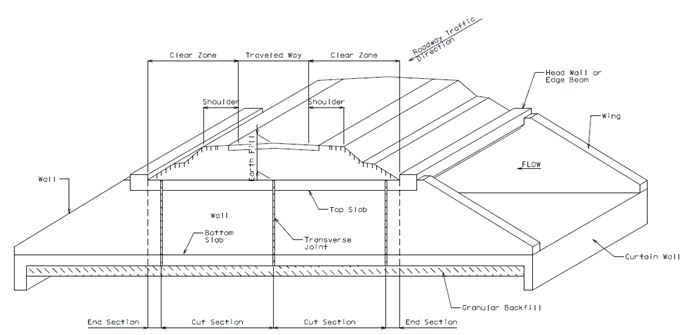
Details of standard box culverts are available in Missouri Standard Plans for Highway Construction. See EPG 750.7.4.1 Standard Plans for an index to the Box Culvert Standard Plans and a table showing the Standard Box Culvert Sizes. A typical box culvert is shown in Figure 751.8.1.2.1. In this figure, a cut section is defined as the section between two transverse joints.
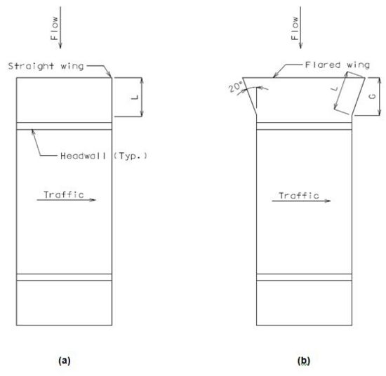
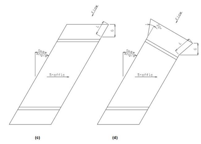
There are four types of standard box culverts shown in Figure 751.8.1.2.2. Type 1 is a square box with straight wings; Type 2 is a square box with flared wings (upstream end only); Type 3 is a skewed box with straight wings; and Type 4 is a skewed box with flared wings (upstream end only).
A box culvert built on a rock foundation is a three-sided box, but is referred to in this article as a box culvert on rock foundation, and is considered a nonstandard box culvert.
751.8.1.3 Barrel Section Dimensions
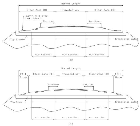
Barrel length is defined as the distance measured along the centerline of the box culvert between inside faces of headwalls. Figure 751.8.1.3.1 shows details of barrel length, fill slope, clear zone, etc.
A section between two transverse joints is called a “cut section” as shown in Figure 751.8.1.3.1. The maximum cut section length is 50 feet. A length of 60 feet may be used in special cases, such as if the joint falls under the traveled way. For more information on locating transverse joints, see EPG 751.8.3.1.
Top Slab
In order to provide adequate clearances for four layers of reinforcement the minimum slab thickness shall not be less than 8”. The slab shall have a uniform thickness and increments of 1”.
If the design fill is less than 1 foot, the minimum slab thickness shall be checked per LRFD 2.5.2.6.3. See the Structural Project Manager or Structural Liaison Engineer for possible use of epoxy coated reinforcing bars, higher concrete strength, etc.
Bottom Slab
In order to provide adequate clearances for four layers of reinforcement the minimum slab thickness shall not be less than 8”. The slab shall have a uniform thickness and increments of 1”.
Walls
The wall shall have a uniform thickness and increments of 1”. Minimum wall thickness shall not be less than 8”. To avoid an undersized wing wall, when the barrel height exceeds 15’ the wall thickness shall not be less than 11”.
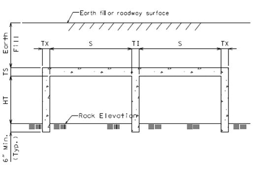
When a box culvert is built on a rock foundation without a bottom slab, the bottom of walls shall be keyed into the rock 6” (min.) for the full length of the walls as shown in Figure 751.8.1.3.2. When built on soft rock or shale, keying the walls in deeper than 6” (min.) shall be considered. See Sec 206.4.2.
Special Sections
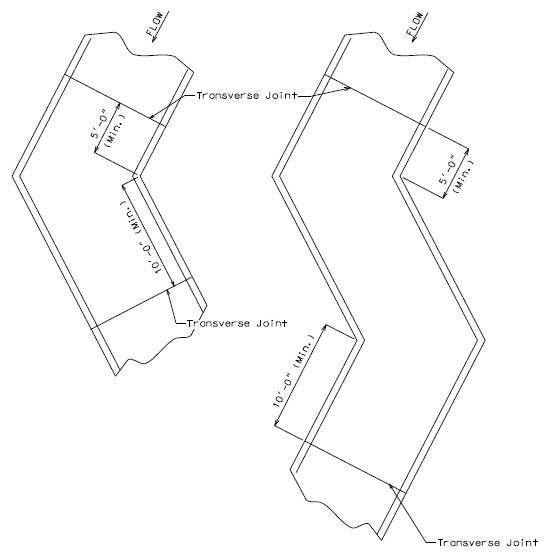
There are two types of special sections called “Dog-Leg” and “Broken Back”. Dog-Leg and Broken Back culverts are defined as sections of box culvert having single and double bends along their lengths, respectively (Figure 751.8.1.3.3). A transverse joint should not be located within that portion that is 5’-0” upstream or 10’-0” downstream from a point of deflection (bend) as shown in Figure 751.8.1.3.3. For details of transverse joints, see Fig. 751.8.3.1.
End Sections
An end section of barrel is a section which is located between the inside face of headwall and the first transverse joint (Figure 751.8.1.2.1). The minimum end section length measured along the shortest wall from the first transverse joint to inside face of headwall shall be 3’-0”. The 3’ minimum end section length is required to provide a culvert end (barrel, headwall and wing walls) that is structurally sufficient to independently resist hydraulic, undermining, and erosion forces. The 3’ minimum dimension also provides adequate space to develop the J1 and R1 bars that project from the wing walls and headwall, respectively. For more information on locating transverse joints, see EPG 751.8.3.1.
751.8.1.4 Other Dimensions
Wings
Exterior wing can be either straight or flared as shown in Figure 751.8.1.4.1. Figure 751.8.1.4.1(a) shows a typical flared standard wing at a fixed angle of 20 degrees. Figures 751.8.1.4.1(b) and (c) show a straight wing without and with skewed angles, respectively. An interior wing shall always be parallel to the centerline of the adjoined walls. When a culvert is to be built on a rock foundation without a bottom slab, the bottom of wing should be keyed into the rock 6” (min.) as shown in Figure 751.8.1.3.2 or when to be built on soft rock or shale, keying the walls in deeper than 6” (min.) shall be considered.

Wing Thickness
The thickness shall be uniform and same as the adjoining wall.
Wing Slope
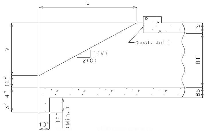
Slope of 1:2 (vertical “V” to horizontal “G”) shall be maintained for both flared and straight wings as shown in Figure 751.8.1.4.2 where “G” is the horizontal length of the wing projection measured perpendicular to the traffic direction as shown in Figure 751.8.1.2.2.
Wing Length
Wing length is determined based on wing height, skewed and flared angles, and wing slope. Exterior wing length, L shown in Figure 751.8.1.2.2 or Figure 751.8.1.4.2, can be determined using Equations (751.8.1.4.1) and (751.8.1.4.2) for straight and flared wings, respectively.
| for straight wings | Equation 751.8.1.4.1 |
| for standard flared wings | Equation 751.8.1.4.2 |
- Where:
- L = wing length
- V = (top slab thk.) + (clear wall ht.) – 12”, refer to Figure 751.8.1.4.2
- θ = skew angle
The exterior wing length is based on the 2:1 wing slope normal to centerline of roadway from the top of the barrel down to a point 12 in. above the top of the bottom slab or to a point 12 in. above theoretical flowline for culverts without a bottom slab. See Structural Project Manager or Structural Liaison Engineer when the wing height at the end of the wing including embedment exceeds 3 ft. for culverts without a bottom slab.
The backfill adjacent to exterior wings is transitioned from the roadway fill slope starting at the inside face of the headwall in accordance with Standard Plan 703.37.
Exterior wing length may be unreasonably long for large skews especially with flared wings or when parallel to an adjacent roadway. See Structural Project Manager or Structural Liaison Engineer when this occurs. Possible solutions:
- With guidance from the Geotechnical Section, use a slope steeper than that shown in Standard Plan 703.37. This will require a special roadway sheet showing the nonstandard slope transition.
- With guidance from the Geotechnical Section, use some form of embankment protection to allow for steeper slopes. This will require additional roadway items.
- Lengthen the culvert to allow for the slope transition shown in Standard Plan 703.37 .
For culverts with a bottom slab, all interior wing lengths shall match exterior wing lengths. Interior wing lengths on a rock foundation shall match exterior wing lengths on the upstream end only. On the downstream end, interior wings on rock shall be omitted beyond the outside face of the headwall. On skewed culverts, interior wings on rock at downstream end shall be made flush with the outside face of the headwall.
Wing Height
The top of wings shall be flush with the top of top slab and they shall be made horizontal for a minimum distance of 3” from outside face of headwall to beginning of wing slope as shown in Figures 751.8.1.4.1 and 751.8.1.4.2.
Flared Wing Angle
Standard flared wing shall make an angle of 20 degrees with respect to exterior wall as shown in Figure 751.8.1.4.1(a) or Figure 751.8.1.3.2(d).
Toe Walls
A toe wall is sometimes also referred to as a curtain wall. Minimum dimensions of toe walls shall be provided at both ends of box culvert. The depth is measured downward from the top of bottom slab to bottom of the toe wall. See Figure 751.8.1.4.2 for details.
Minimum thickness = 10”
Minimum depth = Max {3’-4” or slab thickness + 12”}
Headwalls and Edge Beams
Headwalls shall be provided on all finished culverts to retain fill and strengthen the edge of the top slab. Edge beams shall be provided when transverse joints are skewed from a line normal to centerline of barrel with main reinforcement placed parallel to span. Edge beams should also be considered when skewed or square joints are placed underneath the traveled way for earth fills less than or equal to 2 feet. Note that skewing transverse joints are not recommended, but are sometimes required for staged construction and to keep joints out of the roadway.
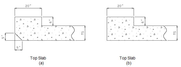
Figure 751.8.1.4.3 shows dimensions for standard headwalls. Use a beveled headwall only at the upstream end and when an edge beam is not required. Faces of headwalls (i.e., both upstream and downstream ends) and edge beams shall be made vertical. Minimum dimensions of headwalls, and recommended minimum dimensions for edge beams, shall be:
- Minimum width = 20” ………………………increments of 1”
- Minimum depth = (top slab thk.) + 6” …...increments of 1”
Collar Beams
Collar beams should be provided at a transverse joint to prevent large differential settlement between adjacent sections. See Figure 751.8.3.2.4 for details. Collar beam dimensions shall meet the following requirements:
- Minimum depth = 12” for top and wall beams
- = 13” for bottom beam only
- Minimum width = 2’-6”
For unique situations where either the cutting details provided in the Standard Plans do not apply, for example, where an existing headwall or wing walls be used-in-place, or where a collar may provide stability in weaker soils or a connection for adjoining different openings, contact the Bridge Division.
751.8.1.5 Precast Culvert
General
All MoDOT cast-in-place (CIP) concrete box culverts are allowed to be constructed using alternate precast concrete box culvert sections in accordance with Sec 733, unless specified otherwise. The converse is not true and precast concrete box culverts may be specified only. Pay items and quantities shall remain unchanged from those typically used for CIP concrete box culverts. When a box culvert is required to be constructed using precast concrete box culvert sections because of an accelerated timeline for construction, pay item and quantity of the precast box culvert shall be based on the length of the precast culvert to the nearest foot measured along the geometrical center of the culvert floor.
Pedestrian Box
Where a precast concrete box culvert could be used as a pedestrian (or “people”) box for walk-through or bicycle path, having multiple joints typically spaced at not greater than 6 ft. may be unacceptable due to tripping hazards, ponding/freezing (settlement of many smaller length sections) or uncomfortable riding surface. Consideration should also be given to special waterproofing or non-corrosive water stops for watertight construction joints.
Multi-Cells
In multi-cell precast construction the staggered placement of units should be avoided. Staggering units results in an irregular end section that loses continuity over the interior wall(s).
Culvert Ties
Precast box culvert ties in accordance with Sec 733 and Std. Plan 733.00 shall be required for the same reasons as concrete collars are required for CIP concrete box culverts. Typically the regular strength connections details should be used. The extra strength connection details shall be used for special cases requiring higher strengths or greater durability, for example when connecting energy dissipating baffles rings or when under low fills and a roadway. If a precast box culvert is required because of an accelerated timeline and collar beams would otherwise be required then culvert ties shall be specified with the cost of ties being considered completely covered by the contract unit price for the precast box culvert.
751.8.2 Design
Throughout EPG 751.8.2 Design and EPG 751.8.3 Details, the 2’ design fill is used as a cutoff between design equations and reinforcement schemes. The LRFD Design Specifications tend to group the 2’ design fill with deeper fills requiring less conservative criterion for the 2’ design fill. The LRFD Bridge Design Guidelines group the 2’ design fill with shallower fills. Including the 2’ design fill with shallower fills continues the practice set forth in the Missouri Standard Plans for longitudinal steel distribution in the top slab. Aligning design criterion to match these reinforcement schemes results in a consistent design philosophy. Since earth fills are rarely uniform over the section, it makes sense to use a more conservative criterion for the 2’ design fill. In addition, the table in the Missouri Standard Plans use the 2’ design fill and it would not be appropriate to use the less conservative criterion when the 2’ design fill will also be used for fills between 1’ and 2’.
751.8.2.1 Limit States and Factors
Each component shall satisfy the following equation:
- Q =
Where:
- Q = Total factored force effect
- Qi= Force effect
- ηi = Load modifier
- = Load factor
- Φ = Resistance factor
- Rn = Nominal resistance
- Rr = Factored resistance
Limit States
The following limit states shall be considered for box culvert design:
STRENGTH – I
SERVICE – I
Refer to Table 751.8.2.1.1 for Loads and Load Factors applied at each given limit state.
Table 751.8.2.1.1 Load Factors for Box Culvert Design
| Load Description | Load Designation | Strength I | Service I Factor | |
|---|---|---|---|---|
| Max. Factor | Min. Factor | |||
| Dead Load of Members | DC | 1.25 | 0.9 | 1.0 |
| Vertical Earth Pressure | EV | 1.30 | 0.9 | 1.0 |
| Horizontal Earth Pressure | *EH (barrel) | 1.35 | 1.0 | 1.0 |
| EH (wings) | 1.50 | NA | 1.0 | |
| Water Pressure | WA | 1.00 | 0.0 | 1.0 |
| Live Load | LL | 1.75 | 0.0 | 1.0 |
| Dynamic Load Allowance | IM | 1.75 | 0.0 | 1.0 |
| Live Load Surcharge | *LS | 1.75 | 1.0/0.0 | 1.0 |
| * The maximum factor should be applied with the maximum equivalent fluid pressure, and the minimum factor should be applied with the minimum fluid pressure. Live load surcharge, LS, is neglected when live load is neglected. See EPG 751.8.2.4. | ||||
Resistance Factors
STRENGTH limit state,
- Flexure, Φ = 0.90 for all members
- Shear, Φ = 0.85 for buried members
- Shear, Φ = 0.90 otherwise
For all other limit states, Φ = 1.00
Load Modifiers
For loads where a maximum value of load factor is appropriate:
For loads where a minimum value of load factor is appropriate:
Where:
- ηD = Modifier relating to ductility
- ηR = Modifier relating to redundancy
- ηI = Modifier relating to operational importance
| Load Modifiers for Box Culvert Design | |
|---|---|
| All Limit States | |
| Ductility, ηD | 1.0 |
| Redundancy, ηR | 1.0 |
| Operational importance, ηI | 1.0 |
| η = (ηI ηR ηD) | 1.0 |
| 1.0 | |
751.8.2.2 Design Fill
Design fill is defined as the earth fill depth used in culvert analysis and design resulting in the greatest structural demand. Earth fill is a backfill or fill that is placed on the top slab. Earth fill depth is defined as the distance between the top of top slab to the top of earth fill or roadway surface as shown in Figure 751.8.1.2.1.
For culverts having an earth fill that varies in depth due to roadway gradient, sloping barrel, or superelevation, the earth fill depth shall be determined as follows:
If the culvert, or any part of the section to be designed, is under a roadway the design of the box or full cut section between transverse joints is based on an earth fill depth at a high or low quarter point, whichever produces maximum load effects, between roadway shoulders.
If a section is under the fill slope outside of roadway shoulders, use an earth fill depth at a high quarter point between fill depths of that section.
Earth fill depth other than stated above should not be used without the permission of the Structural Project Manager or Structural Liaison Engineer.
751.8.2.3 Dead Loads
Dead loads are weight of earth fill and self-weight of concrete members as shown in Figure 751.8.2.5.1. For unit weights of materials, see EPG 751.8.1.1.
Top Slab (DC1 & EV1)
Earth fill weight and self-weight of slab shall be applied uniformly on the top slab. As shown in Figure 751.8.2.5.1, EV1 and DC1 represents earth fill weight and self-weight of top slab, respectively.
The weight of earth fill shall be increased for soil-structure interaction. The soil-structure interaction factor, Fe, for embankment installations is taken as follows:
Where:
- H = Design fill depth
- Bc = total width of culvert normal to centerline
Bottom Slab (DC2 & EV1)
Total dead load (DC2) from self-weight of walls and DC1 shall be applied uniformly on the bottom slab. Earth fill weight (EV1) shall be applied uniformly on the bottom slab. See Figure 751.8.2.5.1 for load directions.
Walls
The self-weight of the wall may be neglected for wall design only.
Wing Walls
The self-weight of the wall may be neglected for wall design only.
Headwalls and Edge Beams
Earth fill and slab weights are assumed to apply as a triangular load on the beam when the beam is skewed. Self-weight of beam and any earth load directly above the beam shall be applied uniformly along the beam length. For square and skewed ends, where the headwall or edge beam is retaining fill, the earth load effect may be ignored and instead the live load is applied directly to the top slab. See EPG 751.8.2.5 for details of load application.
751.8.2.4 Live Loads and Horizontal Pressures
All box culverts shall be designed for only the axle loads of the HL-93 design vehicular live loading. For application of design vehicles the culvert top slab shall be treated as a one-way slab with reinforcement parallel to traffic. Culverts shall be analyzed for a single loaded lane with the single lane multiple presence factor.
Live loads shall be considered under clear zones in the same manner as under roadways (or traveled way) as depicted in Figure 751.8.1.3.1.
Top Slab
The effect of live load distribution varies with different earth fill depths as follows:
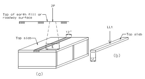
For earth fill depth ≤ 2’-0”, Figure 751.8.2.4.1(a) shows that an axle load is uniformly distributed over a distributed width, E, where this width is perpendicular to a one-foot strip of the top slab. Then, the equivalent concentrated live load (LL1) as shown in Figure 751.8.2.4.1(b) is equal to the axle load (2P) divided by E. The distributed width, E, is determined as:
Perpendicular to span:
- E = 96 + 1.44S
Where:
- E = distributed width for axle loading (in)
- S = clear span length normal to centerline of culvert (ft)
Parallel to span:
Distribution parallel to the span should be conservatively neglected (i.e. point load)
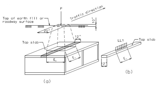
For earth fill depth > 2’-0”, Figure 751.8.2.4.2(a) shows that a uniform patch load, representing the tire contact area, is uniformly distributed over a rectangular area with sides, E1 and E2, where these sides are parallel and perpendicular, respectively, to a one-foot strip width of the top slab. Then, the equivalent uniform live load (LL1 per unit length) as shown in 751.8.2.4.2(b) is equal to the wheel load (P) divided by the product of E1 and E2. The distributed widths, E1 and E2, are determined as:
- E1 = 0.83 + 1.0 H
- E2 = 1.67 + 1.0 H
Where:
- E1 = longitudinal distributed width (ft)
- E2 = transverse distributed width (ft)
- H = design fill depth (ft)
See EPG 751.8.2.5 for applications of distributed live load.
When distribution from wheel lines and/or axles overlap, the total load should be distributed evenly over the area defined by the outer distribution slopes. For single span boxes, the effect of live load may be neglected when the earth fill depth is more than 8’-0” and exceeds the effective span length; for multiple spans, it may be neglected when the earth fill depth exceeds the distance between fill faces of end supports.
Bottom Slab
Use the same transverse distribution width, E2, for top and bottom slab. Longitudinally, a uniformly distributed live load, defined as total live load with impact divided by total length of spans, can be used for analysis.
Where:
- LL2 = equivalent uniform live load per linear foot
- LL1 = live load with impact applied to the top slab
Walls
Live load surcharge, SUR, is modeled as an equivalent soil height times the equivalent fluid pressure of earth fill. The fill height can be interpolated from LRFD Table 3.11.6.4.1 (Table 751.8.2.4.1) where the abutment height is taken as the distance from the top of the design fill to the bottom of the bottom slab or rock. SUR shall be applied uniformly at fill faces of exterior walls (Figure 751.8.2.5.1). Live load surcharge should be neglected if the earth fill depth is more than 8’-0” and exceeds the span length for single span box. For multiple spans, it should be neglected when the earth fill depth exceeds the distance between fill faces of end supports.
| Abutment Height (ft.) | heq (ft.) |
|---|---|
| 5.0 | 4.0 |
| 10.0 | 3.0 |
| ≥ 20.0 | 2.0 |
Headwalls and Edge Beams
For edge beams under fills 2’ or less and for all headwalls a reduced distribution width shall be used. Load application is similar to top slabs for barrel design except the following:
- When at least the minimum headwall dimensions are used the unit strip width shall be equal to the width of the beam.
- The live load effects shall be modeled using the skewed beam length.
- The distribution width, Eedge , calculated for fills ≤ 2 ft. is applicable for wheel loads.
For headwalls:
- Eedge = (headwall width) + 12 + E/4 ≤ E/2
Where:
- Eedge = distribution width for wheel loads near slab edges (in.)
- Eedge = 96 + 1.44 Sedge, with Sedge =
- θ = skew angle
- IM = 1.33
For edge beams under fills ≤ 2 ft.:
- Eedge = 10 + E/4 ≤ E/2
The value “10” in the above equation is equal to ½ the wheel width specified in LRFD 3.6.1.2.5.
Horizontal Pressures
- Barrel Section
- The following properties shall be used on all box culvert designs:
- Minimum equivalent fluid pressure, Pe1 = 30 lbs/ft.3
- Maximum equivalent fluid pressure, Pe2 = 60 lbs/ft.3
- Minimum water pressure, Pw1 = 0.0 lbs/ft.3
- Maximum water pressure, Pw2 = 62.4 lbs/ft.3
- Maximum or minimum equivalent fluid pressure (EP) due to soil shall be applied at fill faces of exterior walls. Water pressure (WP) shall also be applied at these walls to simulate a case when a culvert is full of water. Only exterior walls are subjected to these loads as shown in Figure 751.8.2.5.1.
- Wing Section
- Coulomb active soil pressure or Rankine active formula may be used for horizontal pressures at exterior wing walls only. Neglect passive pressure due to water. For structural model, see EPG 751.8.2.5. For vertical steel reinforcement design, Coulomb active force can be calculated as:
| Equation 751.8.2.4.5 | |
| Equation 751.8.2.4.6 |
- Where:
- Pa = resultant horizontal force of active earth pressure (k)
- Ka = Coulomb active earth coefficient
- H = design height of wing wall (ft.), (Figure 751.8.2.5.2)
- = effective unit weight of backfill (kcf)
- θ = angle of fill face of wall to the horizontal (deg.)
- β = backfill angle to the horizontal (deg.)
- Φ'f = effective internal friction angle of backfill (deg.), (conservatively use 27° if backfill property is not available)
- δ Φ = angle of wall friction (or see LRFD Table 3.11.5.3.1)
- Horizontal steel reinforcement shall be designed only when the wing is nonstandard or built on a rock foundation. Then, Coulomb active force should be determined as:
| Equation 751.8.2.4.7 |
- Where:
- Ph = resultant force of active earth pressure
- Hi = height from the top of wing to the centroid of a one-foot width section (See Figure 751.8.2.5.3)
- A = rectangular area of a one-foot width section (See Figure 751.8.2.5.3)
- Dynamic Load Allowance
- The dynamic load allowance shall be considered for all members with design fills less than 8’. Dynamic load effects will decrease as the earth fill increases and is calculated as follows:
- IM = 33 (1.0 - 0.125DE) ≥ 0%
- Where:
- IM = dynamic load allowance for vehicular axle loads
- DE = design fill depth (ft.)
751.8.2.5 Structural Model
In the analysis of continuous and rigid frame members, the span length or height should be the distance from center to center (the geometric centers) of members. For box culverts on rock, the effective height is defined as the height from rock elevation (Figure 751.8.1.3.2) to the geometric center of the top slab.
Structural Model for Cut Sections
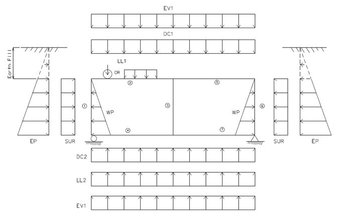
A structural model is analyzed as a rigid frame structure with a one-foot strip width perpendicular to the centerline of culvert (Figures 751.8.2.4.1 and 751.8.2.4.2). As shown in Figure 751.8.2.5.1, the boundary conditions are:
- 1) no lateral and vertical displacements at right end of the bottom slab and
- 2) no vertical displacement at left end of the bottom slab.
For nonstandard box culverts on a rock foundation, a pinned support at each wall is assumed at the rock elevation.
See Figure 751.8.2.5.1 for details of loads and load directions. DC1 is dead load from top slab; EV1 is dead load from earth fill; DC2 is dead loads from DC1 and walls; SUR is a live load surcharge; EP is equivalent fluid pressures; WP is water pressure; and LL1 and LL2 are live loads specified in EPG 751.8.2.4.
Structural Model for Wing Walls
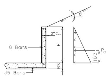
Figure 751.8.2.5.2 shows a typical cross-section of a wing wall. Self-weight, water pressure, and live load surcharge are neglected. Only active earth pressure is applied at exterior wing wall as described in EPG 751.8.2.4. The resultant force Pa of active pressure is applied at (1/3)H from the bottom of wing wall where H is the design wing height. Since the wing wall height varies along its length due to wing slope, the design wing height can be determined at a high quarter point of wing length. The wing wall should be analyzed and designed as a one foot vertical cantilever beam.
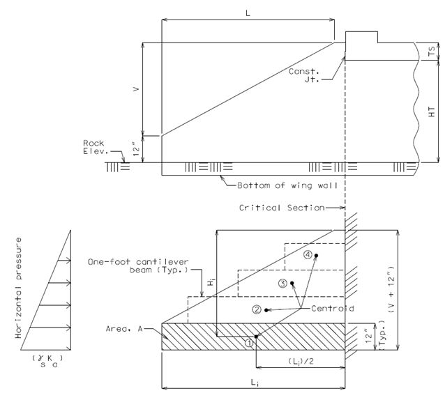
For wing walls on rock, vertical steel reinforcement should be analyzed and designed using the same procedure as wing wall with the bottom slab as given above. Horizontal steel reinforcement should be analyzed and designed as a horizontal cantilever beam. Figure 751.8.2.5.3 shows elevation view and structural model of an exterior wing wall. Figure 751.8.2.5.3 shows that force Phi shall be applied at the Centroid Phi located at height Hi and (Li)/2. Moment and shear should be determined for each one-foot width section and checked at the critical section as shown in the figure.
Structural Model for Headwalls and Edge beams
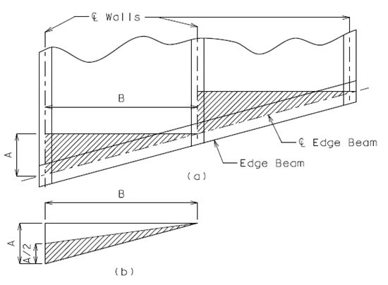
A simple model of headwall or edge beam is shown in Figure 751.8.2.5.4. Dead load due to weights of slab and earth fill is computed based on a triangular hatched area shown in Figure 751.8.2.5.4(a). Assume half of this dead load is supported by the wall and the other half supported by the beam as shown in Figure 751.8.2.5.4(b). Additionally, self-weight of beam and earth fill weight above the beam shall be applied as uniform loads along the beam. For headwall design, the sloping side fill inside the hatched area may be ignored if live load is considered with the maximum dynamic load allowance (IM=1.33). The beam is treated as a continuous beam with pinned supports. When the skewed clear span length exceeds 20 feet, refined methods of analysis are recommended.
751.8.2.6 Structural Design
751.8.2.6.1 Strength Limit Design
Flexural Strength
Factored flexural resistance, ΦMn, of a member at a cross-section should not be less than the factored moment, Mu, at that cross-section. When moment capacity is less than factored moment, increase steel area or thickness of the member. Critical locations for flexural strength design are near the mid-span and at the stream face of adjoining members.
| Equation 751.8.2.6.1 | |
| Equation 751.8.2.6.2 | |
| Equation 751.8.2.6.3 |
The required steel area can be determined by Equation 751.8.2.6.4.
| As = ρ b d | Equation 751.8.2.6.4 |
| Equation 751.8.2.6.5 | |
| Equation 751.8.2.6.6 |
Where:
- As = required steel area (in2)
- b = strip width for design, usually 12 in.
- d = the effective depth from the extreme compression fiber to the centroid of the tensile reinforcement (Note: thickness of monolithic wearing or protective surface shall be excluded at the compressive face of the section where applicable. See EPG 751.8.3.2 Steel Reinforcement.)
- ρ = required steel ratio (a ratio of steel to concrete areas of a section)
- Mu = factored moment (k-in)
- Φ = 0.9 = strength reduction factor for flexure
Maximum Tensile Steel Reinforcement
The maximum amount of tensile reinforcement shall be such that:
| Equation 751.8.2.6.7 |
Where:
- c = the distance from the extreme compression fiber to the neutral axis
Minimum Tensile Steel Reinforcement
The amount of tensile reinforcement shall be adequate to develop a factored flexural resistance, Mr, at least equal to the lesser of:
- 1) Mcr = cracking moment LRFD Eq. 5.7.3.3.2-1
- 2) 1.33 times the factored moment required by the applicable strength load combinations specified in LRFD Table 3.4.1-1.
Shear Strength
Maximum design shear should be checked at a distance “dv” from the stream face of support where “dv” is the effective shear depth of a section. Factored shear resistance, ΦVn, should be provided only by shear strength of concrete and it should not be taken less than factored shear, Vu.
| Equation 751.8.2.6.8 |
When the shear capacity of slabs and walls specified in Equation 751.8.2.6.8 is less than factored shear, increase thickness of the section. For headwalls and edge beams, strength of shear reinforcement, in addition to concrete shear strength, shall be considered. Therefore, the required area of shear reinforcement shall be computed as follows:
| Equation 751.8.2.6.9 | |
| Equation 751.8.2.6.10 |
Where:
- Av = required area of shear reinforcement (in2)
- Vs = shear force to be resisted by shear reinforcement
- Vc = nominal shear strength provided by concrete and given in Equation 751.8.2.6.11 or 751.8.2.6.12
- s = spacing of shear reinforcement steel (in.)
Nominal shear strength should be determined as follows:
For slabs with earth fill ≤ 2’ and all walls
| Equation 751.8.2.6.11 |
For slabs with earth fill > 2’
| Equation 751.8.2.6.12 |
- but
Equation 751.8.2.6.13
Where:
- Vu = factored shear
- Mu = factored moment occurring simultaneously with Vu at the section considered
- dv = effective shear depth as determined in LRFD 5.8.2.9
| Equation 751.8.2.6.14 |
For member sizes less than 16 in. the value of β may be taken as the maximum of 2.0 (Simplified Procedure) and LRFD Eq. 5.8.3.4.2-2 (General Procedure). For member sizes not less than 16 in., β should be calculated using the General Procedure only.
| .....General Procedure | Equation 751.8.2.6.15 |
Where:
| Equation 751.8.2.6.16 | |
| Equation 751.8.2.6.17 |
- Mu = factored moment, not to be taken less than Vudv
- Nu = factored axial force, negative if compressive
- As = area of reinforcing steel on the flexural tension face
- ag = maximum aggregate size = 0.75 in.
For headwalls, edge beams, and wing walls, use Equation 751.8.2.6.11 to determine the nominal shear resistance of concrete.
Headwall and Edge Beams
A minimum steel area of shear reinforcement in Equation 751.8.2.6.19 should be provided in flexural members when factored shear exceeds one-half of concrete factored shear resistance in Equation 751.8.2.6.18.
| Equation 751.8.2.6.18 | |
| Equation 751.8.2.6.19 |
Where:
- Vc = nominal shear resistance provided by concrete section only
- Φ = 0.9 = strength reduction factor for shear
- Av = required steel area of shear reinforcement (in2)
- b = width of section (in)
- s = spacing of shear reinforcement steel (in.)
Slenderness Effect in Wall Members
Slenderness effects shall be considered for all interior walls and for only exterior walls keyed into rock. Exterior walls with bottom slabs will not fail combined axial and flexural resistance checks when the flexural design is adequate. A magnified moment shall be used for the design if the slenderness effect is considered.
For sizing walls the following requirement may be used as a practical constraint:
| Equation 751.8.2.6.20 |
For steel reinforcement design, the slenderness effect may be neglected if Equation 751.8.2.6.21 is satisfied.
| Equation 751.8.2.6.21 |
Where:
- K = 0.65 for interior walls with bottom slab
- = 1.0 for exterior walls on rock
- = 0.80 for interior walls on rock
- Lu = unsupported length (clear wall height)
- r = radius of gyration and may be assumed as 0.3 times member thickness
- M1 = smaller end moment of a wall member
- M2 = larger end moment of a wall member
- = positive or negative value if the member is bent in single or double curvature, respectively.
Magnified Moment
The following procedure is only applicable for walls with Klu/r less than 100. A magnified factored moment, Mm, shall be computed as follows:
| Mm = δb M | Equation 751.8.2.6.22 |
| Equation 751.8.2.6.23 | |
| Equation 751.8.2.6.24 | |
| Equation 751.8.2.6.25 | |
| Equation 751.8.2.6.26 |
Where:
- Mm = magnified moment
- δb = moment magnification factor for a member braced against side sway (preferably less than 2.5)
- M = largest moment of the wall member due to factored loads or minimum eccentricity
- βd = ratio of maximum factored dead load moment to maximum factored total load moment and it is always positive
- Ec = modulus of elasticity of concrete
- Ig = moment of inertia of a gross concrete section (one-foot strip)
- Pe = Euler buckling load
- Pu = factored axial load
- Φ = 0.75 for axial compression with tied stirrups
The moment resulting from an axial load applied at a minimum eccentricity can be calculated as follows. Effects of eccentric axial loads need not be considered for exterior walls.
| Me = Pue | Equation 751.8.2.6.27 |
Where:
- e = minimum eccentricity (in.)
- h = wall thickness (in.)
Wall Capacity due to Combined Axial and Flexural Loads
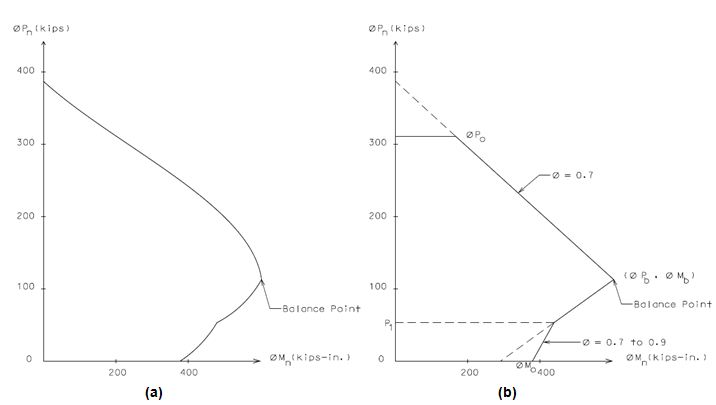
When a wall member is subjected to both axial and flexural loads, the design of such member should consider axial load – flexural moment interaction effect (i.e., “interaction diagram”). Figure 751.8.2.6.1(a) shows a typical interaction diagram. A simplified interaction diagram can be approximately generated using a linearized curve as shown in Figure 751.8.2.6.1(b).
The following procedure should be used for generating a simplified interaction diagram.
1) Determine the factored axial resistance (ΦPo):
| ΦPo = (Φ) { 0.85f'c (Ag - Ast) + Astfy } | Equation 751.8.2.6.28 |
Where:
- Ag = gross area of a cross-section (in.2)
- Ast = total area of steel reinforcement (in.2)
- Φ = 0.75 for axial compression with tied stirrup
2) Determine the maximum factored axial resistance (ΦPn):
| ΦPn = 0.80 (Φ) Po | Equation 751.8.2.6.29 |
3) Determine the balance point (ΦPb, ΦMb): Axial load (ΦPb) and moment (ΦMb) are determined by Equations 751.8.2.6.30 and 751.8.2.6.31, respectively.
| ΦPb = (Φ) [ 0.85f'c ( b )( ab ) + A's f's - As fy ] | Equation 751.8.2.6.30 |
| Equation 751.8.2.6.31 |
Where:
| Equation 751.8.2.6.32 | |
| Equation 751.8.2.6.33 |
- As = total area of tensile reinforcement (in.2)
- A’s = total area of compressive reinforcement (in.2)
- d’ = distance from concrete compressive surface to the centerline of compressive steel reinforcement (in.)
- d” = distance from centerline of tensile reinforcement to the centroid of gross section of member (in.)
- Φ = 0.75
4) Determine the pure bending design moment capacities (ΦMo, ΦMn): If Equation 751.8.2.6.34 is satisfied then the bending moment is determined by Equation 751.8.2.6.35. Otherwise, use Equation 751.8.2.6.2.
| Equation 751.8.2.6.34 | |
| Equation 751.8.2.6.35 |
Where:
- … for Equation 751.8.2.6.35 only.
| Φ Mo = 0.75 Mn | Equation 751.8.2.6.37 |
| Φ Mn = 0.9 Mn | Equation 751.8.2.6.38 |
5) Strength resistance factor, Φ, may be increased linearly from a value of compressive member to a value of flexural member as the design axial load, ΦPn, decreases from smaller value of ΦPb or Equation 751.8.2.6.39 to zero. See Figure 751.8.2.6.1(b) for details.
| P1 = 0.1 f'c Ag | Equation 751.8.2.6.39 |
751.8.2.6.2 Service Limit Design
Crack Control
All concrete members of box culverts except wing walls shall be checked for crack control *(except as noted below). The spacing of tensile steel reinforcement shall be limited by the following equation:
| Equation 751.8.2.6.40 |
Where:
- s = average spacing of tensile steel reinforcement
- = 1.0. (0.75 recommended for top slabs used as a riding surface)
- dc = thickness of concrete cover for tensile reinforcement (in.)
| Equation 751.8.2.6.41 |
Where:
- h = wall or slab thickness. Remove any applicable wearing surfaces when they are on the compression face (in.)
- fs = tensile stress in steel reinforcement at the service limit state (ksi)
When members are subject to significant compressive loads the following formulas shall be used for flexural members with axial thrust:
| Equation 751.8.2.6.42 |
Where:
- Ms = Service moment…always positive (k-in)
- Ns = corresponding axial force…positive for compression (k)
| j = 0.74 + 0.1(e/d) ≤ 0.9 | Equation 751.8.2.6.43 |
| i = 1/(1-jd/e) | Equation 751.8.2.6.44 |
Where:
| e = Ms/Ns + (d – h/2) | Equation 751.8.2.6.45 |
| e/d ≥ 1.15 |
- * If e/d < 1.15 then crack control need not be checked for the location under investigation. When e/d is less than 1.15, the rectangular member is presumed to behave like an eccentrically loaded column rather than a flexural member. Because of this, interior walls need not be checked for fills greater than 2 ft.
When members are subject to insignificant compressive loads the following formulas should be used for members in pure flexure:
| Equation 751.8.2.6.46 |
Where:
| j = 1 - k/3 | Equation 751.8.2.6.47 |
| Equation 751.8.2.6.48 | |
| Equation 751.8.2.6.49 |
751.8.2.6.3 Other Design Requirements
Distribution of Steel Reinforcement
Longitudinal distribution reinforcement (parallel with the centerline of structure) at the bottom of the top slab shall be provided to distribute the concentrated live load when the design fill is two feet or less. For culverts with design fills less than one foot, the amount of distribution reinforcement shall be the percentage of main steel reinforcement for positive moment given as follows:
| Equation 751.8.2.6.50 |
Where:
- S = clear span length (ft.)
Otherwise, for fills less than or equal to 2’:
- Use #4 bars at 14” centers
| #4 bars at 14” centers should also be distributed in the top of the top slab so that four layers of steel reinforcement (two transverse and two longitudinal) are present throughout the top slab. |
Reinforcement for Temperature and Shrinkage
Buried culverts are not exposed to daily temperature changes. The current longitudinal steel reinforcement layout as shown in Figure 751.8.3.2.1 is considered adequate for handling longitudinal stress demands regardless of member size.
Design for temperature and shrinkage shall be required for top slabs of culverts used as a riding surface. The total area of reinforcement per foot, on each face and in each direction for temperature and shrinkage shall meet the following requirements:
| Equation 751.8.2.6.51 | |
| Equation 751.8.2.6.52 |
Where:
- As = area of reinforcement in each direction and each face (in2/ft.)
- w = dimension from fill face to fill face for slabs, clear height for walls (in.)
- t = thickness of wall or slab (in.)
Spacing Limit of Steel Reinforcement
See EPG 751.5.9.2.5 Spacing Limits.
751.8.3 Details
751.8.3.1 Joints
Construction Joints
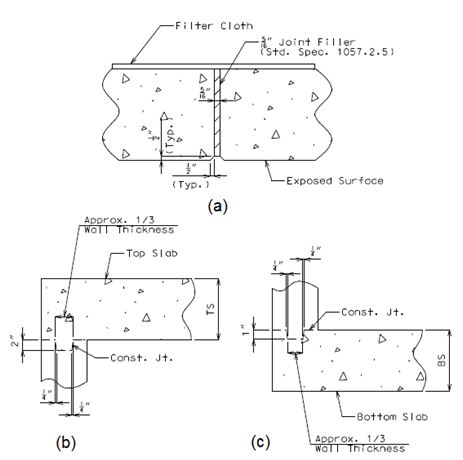
Construction joints shall be located where headwalls and wings meet as shown in Figures 751.8.1.4.1 and 751.8.1.4.2. Keyed construction joints are located at top and bottom of walls. The width of keyed construction joints shall be at least 1/3 of wall thickness with sides battered ¼” in depth. The depth of the key shall be 1” and 2” at the bottom and top of wall, respectively. See Figure 751.8.3.1(b) and (c) for details.
Transverse Joints
A transverse joint shall be provided in all box culverts having barrel length over 80’-0” between inside faces of headwalls measured along the centerline of box culvert. For culverts with clear zones, wide roadways, etc., where the barrel length (Figure 751.8.1.3.1) between inside faces of headwalls measured along centerline of culvert does not exceed 90’-0”, the joint may be omitted. For box culverts with long barrel length, additional transverse joints may be required. A transverse joint shall not be placed less than 3’ along any wall or more than 50’ along centerline of culvert from the inside face of the headwall. For the maximum length of a cut section between two transverse joints, see EPG 751.8.1.3. For guidelines specific to locating transverse joints in culvert extensions, see EPG 751.8.3.5 Miscellaneous.
If possible, transverse joints shall not be placed directly below traveled way. Locate the joint under shoulders or median. Transverse joints shall not be located under a traveled way with design fills 2 ft. or less.
All transverse joints shall be made vertical when the culvert is cambered, indicate vertical on plans, and at right angles to the centerline of barrel. All longitudinal steel reinforcement shall be stopped at least 1-1/2” from joints. These joints shall be filled with 5/16” joint filler. See Figure 751.8.3.1(a) for details.
751.8.3.2 Steel Reinforcement
Barrel Section
Standard boxes shall have main reinforcement placed perpendicular to the centerline of culvert. In any case, main reinforcement should not be skewed more than 25° from a line normal to the centerline of the culvert. (See LRFD 9.7.1.3.) The bar sizes, spacings and lengths given in the Standard Plans 703.17, 703.47 and 703.87 are applicable for uncoated steel reinforcement. Figure 751.8.3.2.1 shows a typical cross-section of standard box culvert and bar marks of steel reinforcement which are described below:
A1 bar - Steel reinforcement shall be designed for maximum positive moment in the top slab. This bar is placed transversely perpendicular to the centerline of culvert at the bottom of top slab. Place A1 bars into headwall or edge beam as close as practical.
A2 bar - Steel reinforcement shall be designed for maximum positive moment in the bottom slab. This bar is placed transversely perpendicular to the centerline of culvert at the top of bottom slab.


B1 bar - Steel reinforcement shall be designed for maximum combined axial load and moment at interior walls. This bar is placed vertical near stream faces of the wall. Minimum steel reinforcement of #5 bars spaced at 12” centers shall be provided. This bar should be extended into the top and bottom slabs. A hook bar may be required if the embedment length is insufficient due to slab thickness limitations. [[751.5 Standard Details#751.5.9.2.8.1 Development and Lap Splice General|EPG 751.5.9.2.8.1 Development and Lap Splice General] has information pertaining to development of tension reinforcement and hooks.
B2 bar – For culverts with bottom slabs, steel reinforcement shall be designed for the maximum positive moment in the exterior wall. For culverts on rock, steel reinforcement shall be designed for the maximum combined positive moment and axial load. This bar is placed vertical near the stream face of the wall. Minimum steel reinforcement of #5 bar spacing at 12” centers shall be provided. This bar should be extended into the top and bottom slabs. A hook bar may be required if the embedment length is insufficient due to slab thickness limitations. EPG 751.5.9.2.8.1 Development and Lap Splice General has information pertaining to development of tension reinforcement and hooks.
J3 bar - Steel reinforcement shall be designed for the maximum negative moment in the top corner of the culvert. This bar is placed vertical along the wall and transversely perpendicular to the centerline of culvert.
J4 bar - Steel reinforcement shall be designed for maximum negative moment in the bottom corner of the culvert. The J4 bar should also be designed for the maximum negative moment near the mid-height of the exterior wall. This bar is placed vertical along the wall and transversely perpendicular to the centerline of culvert.
H1 bar - Steel reinforcement shall be designed for the maximum negative moment in the top slab over the interior walls. This bar is placed transversely perpendicular to the centerline of culvert at the top of top slab. Its spacing is alternated with spacing of H2 bar. The length of H1 bar is longer than the length of H2 bar.
H2 bar - Steel reinforcement shall be designed for the maximum negative moment in the top slab over the interior walls. This bar is placed transversely perpendicular to the centerline of culvert at the top of top slab. Its spacing is alternated with spacing of H1 bar.
F bar - Longitudinal steel reinforcement provides for temperature and shrinkage control. Use #4 bars at about 14” centers for all interior faces. A minimal number of longitudinal bars in exterior faces are also provided primarily to aid in construction. This bar is placed parallel to the centerline of culvert. Additional longitudinal reinforcement may be required to provide for lateral distribution of concentrated live loads. For distribution of reinforcement, see EPG 751.8.2.6.
Headwalls and Edge Beams
Figure 751.8.3.2.2 shows a typical cross-section through headwalls and edge beams, and bar marks of steel reinforcement which are described below. The reinforcement values given below shall be considered standard for headwalls and minimum recommended values for edge beams.
If at least the minimum headwall dimensions are provided (see Fig. 751.8.3.2.2) the steel reinforcement in the top slab need not be increased over that required for barrel design. Otherwise, the width of the edge beam shall be taken as 3 feet and additional reinforcement in the top and bottom of slab is required.
D1 bar – Place 2- #8 bars at the top of headwalls or edge beams. These bars shall be placed along the headwall or edge beam.
D2 bar – Place these bars between D1 bars at the top of headwalls or edge beam and centered over interior walls. The total length of the bar is equal to two times larger value of 48 bar diameters or ¼ clear span length of headwall or edge beam. Neglect this bar for single span and if clear span length along headwall is less than or equal to 10’ for multiple spans. Otherwise, use a number of bars and sizes as indicated below:
- 2- #8 bars when 10’ 13’
- * 2- #9 bars when 13’
* The required area of steel reinforcement should be checked if clear span length along edge beam exceeds 20’.
H bar - Provide 4- #8 bars at bottom of headwalls or edge beam when edge beam is skewed. These bars shall be placed along the headwall or edge beam.
R1 bar – Provide minimum #5 bar spacing at 12” centers. This bar is placed perpendicular to longitudinal axis of upstream headwall or edge beam.
R2 bar - Provide minimum #5 bar spacing at 12” centers. This bar is placed perpendicular to longitudinal axis of upstream headwall or edge beam.
R3 bar - Provide minimum #5 bar spacing at 12” centers. This bar is placed perpendicular to longitudinal axis of downstream headwall or edge beam.

Wings
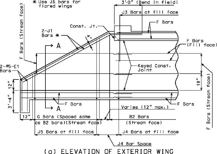
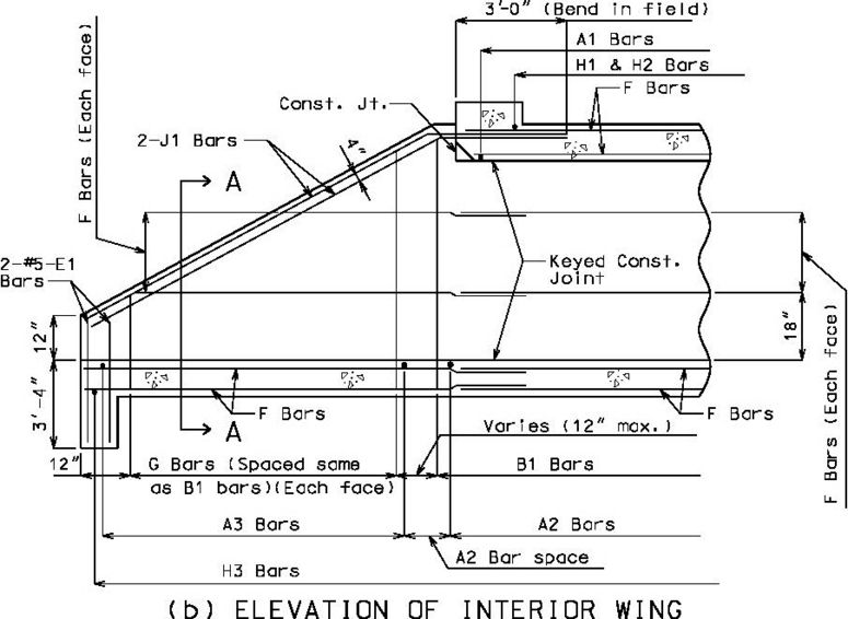
F bar - Longitudinal steel reinforcement provides for temperature and shrinkage control. Use #4 bars at about 14” centers for all interior faces. A minimal number of longitudinal bars in exterior faces are also provided primarily to aid in construction. This bar should be placed longitudinal along wing walls as shown in Figure 751.8.3.2.3. For wings on rock, longitudinal F bars should be designed using maximum moment and shear as specified in EPG 751.8.2.5.
G bar – Provide the same bar size and spacing as B1 or B2 bar for interior (Figure 751.8.3.2.3(b)) or exterior wall (Figure 751.8.3.2.3(a)), respectively.
J1 or J6 bar – Provide 2- #7 bars at each face of wing walls. These bars are provided for edge beam action and for support in extreme event scenarios, such as washout. The J6 callout is used for flared wings.
J5 bar – Steel reinforcement shall be designed for moment and shear based on Coulomb or Rankine active earth pressure. In any case, the provided steel area of J5 bar shall not be less than that provided by the adjoined wall.
Toe Walls
E1 bar – Provide 4- #5 bars and they should extend into wing walls as far as practical as shown in Figure 751.8.3.2.3. For wing walls on rock, these bars shall be extended 12” into the rock and grouted.

Collar Beams
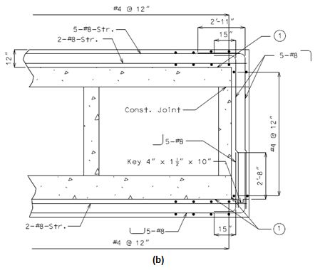
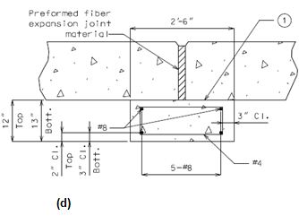
Figure 751.8.3.2.4 shows steel reinforcement details of collar beams. The figure also shows that two layers of roofing felt shall be provided between culvert and collar beams. This will allow free lateral movement of adjoined sections.


| For box culverts where collars are required and the precast option is used, precast concrete box culvert ties in accordance with Sec 733 and Std. Plan 733.00 shall be provided between all precast sections. |
Reinforcement Concrete Cover
The minimum concrete cover shall be 1-1/2” (clear) except the following:
- Top Slab
- The minimum concrete cover shall be 2” (clear) at top and 1-1/2” (clear) at bottom of the slab.
- Bottom Slab
- The minimum concrete cover shall be 1-1/2” (clear) at top and 3” (clear) at bottom of the slab.
- Walls and Wing Walls
- The minimum concrete cover shall be 2” (clear) at fill face and 1-1/2” (clear) at stream face.
- Wearing Surface
- A 1” monolithic protective surface shall be used on the bottom of bottom slab to compensate for pouring concrete on uneven earth surfaces. In special cases, where abrasion on the stream faces is a concern, a 1/2" monolithic wearing surface may be used on stream faces of walls and bottom slab. In the analysis, the protective surface and wearing surfaces (when considered) are included as part of the member thickness, but shall be excluded in the calculation of effective depth of the member for design.
751.8.3.3 Rock Survey Data for Plans
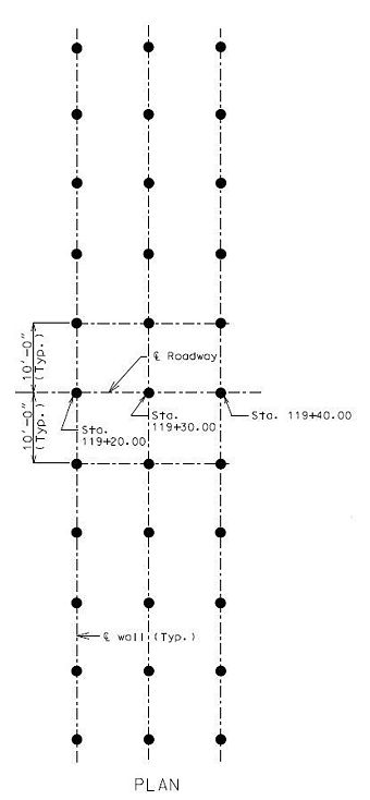
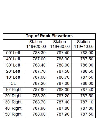
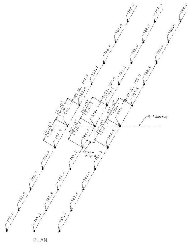
Rock elevations for box culverts with walls on rock or with bottom slab or toe walls that will encounter rock shall be detailed on the plans. Figure 751.8.3.3.1 shows details of Alternative #1 which shall include a sketch of rock locations and a table showing rock elevations. Alternative #2 (Figure 751.8.3.3.2) is similar to Alternative #1 except that rock elevations are shown on a sketch of rock locations.
 |
 |
| Note: See EPG 751.50 A2 for appropriate notes to include on plans. | |
| Instruction: All box culverts on rock shall have the rock elevations shown on the plans at significant changes along each wall. | |
751.8.3.4 Wing Walls on Rock
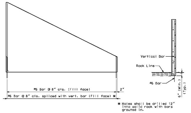
Four rock anchors are typically used at the end of wing walls on rock for securing the wing to the rock which is analogous to using four E1 bars at the end of wing walls on slab.
Wing walls on rock are modeled as fixed cantilevers for both vertical and horizontal steel reinforcement design. Vertical cantilever fixity is assumed to be the same as for a wing wall on slab but because it is embedded into rock, horizontal steel is then designed as if wall is horizontally cantilevered, i.e. ability to deflect about a vertical axis, in accordance with EPG 751.8.2.4 Live Loads and Horizontal Pressures and EPG 751.8.2.5 Structural Model. When there is concern about rock strength or rock degradation and rock erodibility not providing for fixity in the long term as assumed but rather a “pinned” support condition, or when the length and/or height of the wall is excessive, either of which could create a heavy steel reinforcement design, then anchoring the wall deeper into rock or using rock anchors are both options that may provide the fixity necessary for designing a moderate steel reinforcement design. Alternatively a more refined analysis may provide a more accurate reinforcement solution.
751.8.3.5 Miscellaneous
Granular Backfill
The contractor shall furnish granular backfill in accordance with Sec 206 within the limits as shown on the plans when approved by the Engineer. Payment for removal of inherently unsound material will be made at the contract unit price for Class 4 Excavation. The contractor will be reimbursed for the delivered cost of granular backfill when approved by the engineer.
Wing Backfill Slope Transition
Backfill slope transition at wings is determined based on skew angle of box culvert. See Sheet 2 of 2 in Standard Plan 703.37 for slope transition.
Culvert Extensions
When an existing culvert is to be extended, cutting details shall be followed to determine where and how to cut the existing culvert. See Standard Plan 703.38 for cutting details.
A transverse joint is not required when extending the barrel not more than 15 feet. When extensions exceed 15 feet, transverse joint requirements are the same as those for full culverts, see EPG 751.8.3.1.
