|
|
| Line 320: |
Line 320: |
|
| |
|
| ---- | | ---- |
|
| |
|
| |
| =751.39.1 Dimensions=
| |
| Long, narrow footings (length to width ratio ≥ 2.0) supporting individual columns are not desirable, and care should be taken to avoid their use unless space constraints or eccentric loading dictate otherwise.
| |
|
| |
| {|
| |
| |-
| |
| | style="width: 350px;" | [[image:Dim_Side_Elevation_10-26-23.png|center]] || style="width: 350px;" | [[image:Dim_Front_Elevation_10-26-23.png|center]]
| |
| |-
| |
| | <center>'''Side Elevation'''</center> || <center>'''Front Elevation'''</center>
| |
| |}
| |
|
| |
| {|
| |
| |-
| |
| | (1)
| |
| | style="text-align:left;" | Min. = 1/8 x (Distance from top of beam to bottom of footing.)
| |
| |-
| |
| | (2)
| |
| | style="text-align:left;" | 3'-0" (Min.) & 6'-0" (Max.) for steel HP piles, 14" CIP piles. 3D (Min.) and 6D (Max.) for 16”, 20" and 24" CIP piles. (D = pile diameter)
| |
| |-
| |
| | (3)
| |
| | style="text-align:left;" | Indicates column diameter, or column length or width on a hammer head pier.
| |
| |-
| |
| | style="vertical-align:top" | (4)
| |
| |
| |
|
| |
| {| class="wikitable" style="text-align: center"
| |
| |-
| |
| !
| |
| ! Seismic Design Category
| |
| ! Min. Footing Thickness
| |
| |-
| |
| | rowspan="2" | Friction Pile
| |
| | A
| |
| | 2’-6” or column diameter
| |
| |-
| |
| | B, C, D
| |
| | 3’-0” or column diameter
| |
| |-
| |
| | rowspan="2" | HP Pile
| |
| | A
| |
| | 3’-0” or column diameter
| |
| |-
| |
| | B, C, D
| |
| | 3’-0” or column diameter
| |
| |}
| |
| |-
| |
| |
| |
| | Note: For column diameters 4'-0" and greater use a 4'-0" min. footing</br>thickness. If SDC A S<sub>D1</sub> ≥ 0.1, provide seismic details similar to SDC B for applicable routes per [https://epg.modot.org/forms/general_files/BR/Bridge_Seismic_Design_Flowchart.pdf Bridge Seismic Design Flowchart].
| |
|
| |
| |-
| |
| | (5)
| |
| | style="text-align:left;" | 12" for seismic design category A and 18" for SDC B, C, & D. If SDC A SD1 ≥ 0.1, provide seismic details similar to SDC B for applicable routes per [https://epg.modot.org/forms/general_files/BR/Bridge_Seismic_Design_Flowchart.pdf Bridge Seismic Design Flowchart].
| |
| |-
| |
| | (6)
| |
| | style="text-align:left;" | Use 18" for steel HP piles and 14" and 16” CIP piles. The distance from the side of any pile to the nearest edge of the pile footing shall not be less than 9 inches.
| |
| |}
| |
|
| |
|
| |
| {|
| |
| |-
| |
| | style="width: 350px;" | [[image:Typ_Plan_Staggered_Pile_10-26-23.png|center]]
| |
| |-
| |
| | <center>'''TYPICAL PLAN</br>STAGGERED PILE'''<br>(7 Pile Footings shall not be used.)</center>
| |
| |}
| |
| <nowiki>*</nowiki> The maximum pile spacing is 4'-0".
| |
|
| |
| <nowiki>**</nowiki> 3'-0" (Min.) & 6'-0" (Max.) for steel HP piles, 14" CIP piles. 3D (Min.) and 6D (Max.) for 16”, 20" and 24" CIP piles. (D = pile diameter)
| |
|
| |
|
| |
|
| |
|
| |
|
| |
| =751.39.5 Reinforcement=
| |
|
| |
| '''Unreinforced Footing - Use only in Seismic Design Category A'''
| |
|
| |
| The term “unreinforced footing” is used for footings where only #6 hairpin bars are required.
| |
|
| |
| Do not use unreinforced footing if SDC A, S<sub>D1</sub> ≥ 0.1 for applicable routes per [https://epg.modot.org/forms/general_files/BR/Bridge_Seismic_Design_Flowchart.pdf Bridge Seismic Design Flowchart].
| |
|
| |
| Unreinforced footings shall only be used when the shear line for all piles is within the column projected, or where additional flexural steel is not required by design (not typical).
| |
|
| |
| {|
| |
| |-
| |
| | style="width: 275px;" | [[image:Elevation_4_Pile_Footing_A_10-26-23.png|center]] || style="width: 275px;" | [[image:Plan_4_Pile_Footing_A_10-26-23.png|center]]
| |
| |-
| |
| | <center>'''Elevation</br>(4 Pile Footing)'''</center> || <center>'''Plan</br>(4 Pile Footing)'''</center>
| |
| |}
| |
| <nowiki>*</nowiki> See [[751.5_Structural_Detailing_Guidelines#751.5.9.2.8.2_Development_and_Lap_Splices_of_Deformed_Bars_in_Tension|EPG 751.5.9.2.8.2]].
| |
|
| |
| Notes: Use Class B lap splice of deformed bars in tension.
| |
| ::Use for all types of piling.
| |
|
| |
|
| |
| '''Reinforced Footing - Seismic Design Category (SDC) A'''
| |
|
| |
| If SDC A, S<sub>D1</sub> ≥ 0.1, provide seismic details similar to SDC B for applicable routes per [https://epg.modot.org/forms/general_files/BR/Bridge_Seismic_Design_Flowchart.pdf Bridge Seismic Design Flowchart].
| |
|
| |
| {|
| |
| |-
| |
| | style="width: 350px;" | [[image:Front_Elevation_A_10-26-23.png|center]] || style="width: 350px;" | [[image:Side_Elevation_A_10-26-23.png|center]]
| |
| |-
| |
| | <center>'''Front Elevation'''</center> || <center>'''Side Elevation'''</center>
| |
| |-
| |
| | colspan="2" | [[image:Plan_A_10-26-23.png|center]]
| |
| |-
| |
| | colspan="2" | <center>'''Plan'''</center>
| |
| |}
| |
| <nowiki>*</nowiki> See See [[751.5_Structural_Detailing_Guidelines#751.5.9.2.8.2_Development_and_Lap_Splices_of_Deformed_Bars_in_Tension|EPG 751.5.9.2.8.2]].
| |
|
| |
| Notes: Use Class B lap splice of deformed bars in tension.
| |
|
| |
| ::The minimum bar size for flexural steel that meets all design requirements is preferred. Straight bars are preferred to hooked ends.
| |
|
| |
|
| |
| '''Reinforced Footing - Seismic Design Categories B, C & D'''
| |
|
| |
| {|
| |
| |-
| |
| | style="width: 400px;" | [[image:Front_Elevation_BCD_10-26-23.png|325px|center]] || style="width: 400px;" | [[image:Side_Elevation_BCD_10-26-23.png|350px|center]]
| |
| |-
| |
| | <center>'''Front Elevation'''</center> || <center>'''Side Elevation'''</center>
| |
| |-
| |
| | [[image:Plan_Top_BCD_10-26-23.png|395px|center]] || [[image:Plan_Bottom_BCD_10-26-23.png|center]]
| |
| |-
| |
| | <center>'''Plan Showing Top Reinforcement'''</center> || <center>'''Plan Showing Bottom Reinforcement'''</center>
| |
| |}
| |
| For anchorage of piles for seismic details for SDC B, C and D, see [[751.36_Driven_Piles#751.36.4_Anchorage_of_Piles_for_Seismic_Details|EPG 751.36.4 Anchorage of Piles for Seismic Details]].
| |
|
| |
| <nowiki> *</nowiki> For reinforcement in top of the footing and bottom of footing, See [[751.5_Structural_Detailing_Guidelines#751.5.9.2.8.2_Development_and_Lap_Splices_of_Deformed_Bars_in_Tension|EPG 751.5.9.2.8.2]] for lap splice.
| |
|
| |
| : Note: Use Class B lap splice of deformed bars in tension.
| |
|
| |
| <nowiki> **</nowiki>Place the top reinforcement uniformly outside the column reinforcement. Use same area of steel in the top of the footing as is required for the bottom.
| |
|
| |
| For pile footing joint shear reinforcement requirement for SDC C and D, see [[751.9_Bridge_Seismic_Design#751.9.1.2.4.2_Footing_(Spread_Footing_and_Pile_Cap_Footing)_Joint_Shear_Reinforcement|EPG 751.9.1.2.4.2 Footing (Spread Footing and Pile Cap Footing) Joint Shear Reinforcement]].
| |
|
| |
|
| |
|
| |
|
| |
|
| |
|
| |
|
| |
|
| |
| <big><big>'''<font color= red>!!! DARREN should the note before G1.40 include note 1.44 and note 1.45 !!!</font color>'''</big></big>
| |
|
| |
| === G1. Concrete Bents ===
| |
|
| |
| '''Expansion Device at End Bents (G1.1 and G1.1.1)'''
| |
|
| |
| '''(G1.1)'''
| |
| :Top of backwall for end Bent<u>s</u> No. <u> </u> shall be formed to the crown and grade of the roadway. Backwall above upper construction joint<u>s</u> shall not be poured until the superstructure slab has been poured in the adjacent span.
| |
|
| |
| '''(G1.1.1)'''
| |
| :All concrete above the upper construction joint in backwall shall be Class B-2.
| |
|
| |
|
| |
| '''Abutments with Flared Wings'''
| |
|
| |
| '''(G1.2)'''
| |
| :Longitudinal dimensions shown for bar spacing in the developed elevations are measured along front face of abutments.
| |
|
| |
|
| |
| '''Stub Bents (G1.3 and G1.4) '''
| |
|
| |
| '''(G1.3)'''
| |
| :<u>Barrier</u>, <u>parapets</u> <u>and</u> <u>end post</u> shall not be poured until the slab has been poured in the adjacent span.
| |
|
| |
|
| |
| '''(G1.4) Use when embedded in rock or on a footing.'''
| |
| :Rock shall be excavated to provide at least 6" of earth under the <u>beam and wings.</u>
| |
|
| |
|
| |
| '''End Bents with Turned-Back Wings (G1.5 and G1.6)'''
| |
|
| |
| '''(G1.5) Use for Non-Integral End Bents only.'''
| |
| :Field bending shall be required when necessary at the wings for #<u> </u>-H<u> </u> bars in the backwalls for skewed structures and for #<u> </u>-F<u> </u> bars in the wings for the slope of the wing.
| |
|
| |
| '''(G1.6) Add to sheet showing the typical section thru wing detail.'''
| |
| :For reinforcement of the barrier, see Sheet No. <u> </u> (1).
| |
|
| |
| ::(1) Use sheet number of the details of the barrier at end bents.
| |
|
| |
|
| |
| '''Integral End Bents (G1.7 thru G1.10)'''
| |
|
| |
| '''(G1.7) Place with part plan of end bent, second F bar required for skewed bents. '''
| |
| :The #6-F___ <u>and #6-F </u> bars shall be bent in the field to clear <u>beams</u> <u>girders</u>.
| |
| <div id="(G1.7.1) Use for skewed bents."></div>
| |
|
| |
| '''(G1.7.1) Use for skewed bents. Place with plan of beam showing reinforcement and part plan of end bent, V bars not required with part plan of end bent. '''
| |
| :The U bars <u>and pairs of V bars</u> shall be placed parallel to centerline of roadway.
| |
|
| |
| '''(G1.8) Place with part plan of end bent.'''
| |
| :All concrete in the end bent above top of beam and below top of slab shall be Class B-2.
| |
|
| |
| '''P/S Structures (G1.9 and G1.9.1). place with part plan of end bent.'''
| |
|
| |
| '''(G1.9) '''
| |
| :Strands at end of the <u>girders</u> <u>beams</u> shall be field bent or, if necessary, cut in field to maintain 1 1/2-inch minimum clearance to fill face of end bent.
| |
| <div id="(G1.9.1)"></div>
| |
| '''(G1.9.1) Use appropriate girder sheet number. '''
| |
| :For location of coil tie rods and #5-H__(strand tie bar), see Sheet No.___.
| |
|
| |
| '''(G1.10) Use for steel structures without steel diaphragms at end bents.'''
| |
| :Concrete diaphragms at the integral end bents shall be poured a minimum of 12 hours before the slab is poured.
| |
|
| |
|
| |
| '''Semi-Deep Abutments (G1.11 thru G1.13) Place near the ground line and piling in abutment detail. This detail and notes can be placed with abutment details or near the foundation table.'''
| |
|
| |
| '''(G1.11)'''
| |
| :Earth within abutment shall not be above the ground line shown . Forms supporting the abutment slab may be left in place.
| |
|
| |
|
| |
| '''(G1.12)'''
| |
| :The maximum variation of the head of the pile and the battered face of the pile from the position shown shall be no more than 2 inches.
| |
|
| |
|
| |
| '''(G1.13)'''
| |
| :Exposed <u>steel piles</u> <u>steel pile shells</u> within the abutment shall be coated with a heavy coating of an approved bituminous paint.
| |
|
| |
| <div id="All Substructure Sheets with Anchor Bolts"></div>
| |
|
| |
| '''All Substructure Sheets with Anchor Bolts'''
| |
|
| |
| '''(G1.15A)'''
| |
| :Reinforcing steel shall be shifted to clear anchor bolt wells by at least 1/2".
| |
|
| |
| '''(G1.15B) Use unless only anchor bolt wells are preferred, i.e. uplift, congested reinforcement, etc. '''
| |
|
| |
| :Holes for anchor bolts may be drilled into the substructure.
| |
|
| |
|
| |
| '''Beam/Girder Chairs (G1.16 thru G1.19). Notes G1.16 and G1.17 shall be placed near chair details. '''
| |
| <div id="(G1.16)"></div>
| |
| '''(G1.16)'''
| |
| :Cost of furnishing, fabricating and installing chairs will be considered completely covered by the contract unit price for <u>(a)</u>.
| |
| <center>
| |
| {| style="margin: 1em auto 1em auto"
| |
| |-
| |
| |
| |
| {| border="1" cellpadding="3" cellspacing="1" style:"text-align:left"
| |
| |+
| |
| ! style="background:#BEBEBE" |Condition!! style="background:#BEBEBE" |(a)
| |
| |-
| |
| |align="left" width="230"|Structures without steel beam or girder pay item ||align="left" width="230"|Fabricated Structural Carbon Steel (Misc.)
| |
| |-
| |
| |align="left"|Structures with steel beam or girder pay item|| align="left"|Use beam or girder pay item
| |
| |}
| |
| ||
| |
| {| border="1" cellpadding="3" cellspacing="1" style:"text-align:left"
| |
| |-
| |
| |width="250" align="left"|When there is no steel beam or girder pay item, the miscellaneous steel for the chair is a substructure pay item and should also be included in the bent substructure quantity box
| |
| |}
| |
| |}
| |
|
| |
| </center>
| |
| '''(G1.17) Use for P/S structures and for steel structures when the chair material is not the pay item material. '''
| |
| :Steel for chairs shall be ASTM A709 Grade 36.
| |
|
| |
| '''(G1.18) Use for structures with steel beam or girder pay items. Place below the substructure quantity box of all bents with chairs using the same pay item for (a) as used in Note G1.16. '''
| |
|
| |
| :The weight of <u> </u> pounds of chairs is included in the weight of (a).
| |
|
| |
| '''(G1.19) Place with the other bent notes. Second sentence is required when the chair details are located with other bent details. '''
| |
|
| |
| Reinforcing steel shall be shifted to clear chairs. <u>For details of chairs, see Sheet No. </u>.
| |
|
| |
| '''Pile Cap Bents. '''
| |
|
| |
| '''(G1.20) Place with plan showing reinforcement.'''
| |
| :Reinforcing steel shall be shifted to clear piles. U bars shall clear piles by at least 1 1/2 inches.
| |
|
| |
| '''Vertical Drains at End Bents.'''
| |
|
| |
| '''(G1.25) Place with part plan of end bent. '''
| |
| :For details of vertical drain at end bent, see Sheet No.___.
| |
|
| |
| '''Bridge Approach Slab. '''
| |
|
| |
| '''(G1.30) Place with part plan of end bent.'''
| |
| :For details of bridge approach slab, see Sheet No.___.
| |
|
| |
|
| |
| '''Miscellaneous (G1.41 thru G1.43) '''
| |
|
| |
| '''(G1.40) Use the following note at all fixed intermediate bents on prestressed girder bridges with steps of 2" or more. Place with plan of beam.'''
| |
| :For steps 2 inches or more, use 2 1/4 x 1/2 inch joint filler up vertical face.
| |
|
| |
| '''(G1.41a) Use the following note when vertical column steel is hooked into the bent beam for seismic category A.'''
| |
| :At the contractor's option, the hooks of vertical bars embedded in the beam cap may be oriented inward or outward.
| |
|
| |
| '''(G1.41b) Use the following note when vertical column steel is hooked into the bent beam for seismic category B, C or D. '''
| |
| :The hooks of vertical bars embedded in the beam cap shall not be turned outward, away from the column core.
| |
|
| |
| '''(G1.42) Place the following note on plans when using Optional Section for Column-Web beam joints.'''
| |
| :At the contractor's option, the details shown in optional Section __-__ may be used for column-web beam or tie beam at intermediate Bent No. <u> </u>. No additional payment will be made for this substitution.
| |
|
| |
| '''(G1.43) Place the following note on plans when you have adjoining twin bridges.'''
| |
| :Preformed compression joint seal shall be in accordance with Sec 717. Payment will be considered completely covered by the contract unit price for other items included in the contract.
| |
|
| |
| '''(G1.44) Use with column closed circular stirrup/tie bar detail.'''
| |
| :Minimum lap ____ (Stagger adjacent bar splices)
| |
|
| |
| '''(G1.45) Use when mechanical bar splices (MBS) are to be specified on the plans for column and drilled shaft vertical reinforcement.'''
| |
| : When contractor use MBS for column and drilled shaft vertical reinforcement, contractor shall increase diameter of stirrup bars and seismic bars (spiral/hoop) as needed at the MBS locations. No additional payment will be made for this adjustment. Stirrup bars and seismic bars shall not be shifted to create large gaps to avoid MBS.
| |
|
| |
|
| |
|
| |
|
| |
|
| |
| ----
| |
|
| |
|
| |
| ='''REVISION REQUEST 4034'''=
| |
|
| |
| <big><big>'''<font color= red>!!! Only replace first part of 751.9.1 up to 751.9.1.1 !!!</font color>'''</big></big>
| |
|
| |
| ==751.9.1 Seismic Analysis and Design Specifications==
| |
| <div style="float: left; margin-top: 5px; margin: 15px; width:255px; background-color: #f8f9fa; padding: 0.3em; border: 1px solid #a2a9b1; text-align:left;">
| |
| '''<u><center>Additional Information</center></u>'''
| |
| * [https://epg.modot.org/forms/general_files/BR/Bridge_Seismic_Design_Flowchart.pdf Bridge Seismic Design Flowchart]
| |
| </div>
| |
| All new or replacement bridges on the state system shall include seismic design and/or detailing to resist an expected seismic event per the [https://epg.modot.org/forms/general_files/BR/Bridge_Seismic_Design_Flowchart.pdf Bridge Seismic Design Flowchart]. For example, for a bridge in Seismic Design Categories A, B, C or D, complete seismic analysis or seismic detailing only may be determined as per “[https://epg.modot.org/forms/general_files/BR/Bridge_Seismic_Design_Flowchart.pdf Bridge Seismic Design Flowchart]”.
| |
|
| |
| Missouri is divided into four Seismic Design Categories. Most of the state is SDC A which requires minimal seismic design and/or detailing in accordance with SGS (Seismic Zone 1 of LRFD) and “[https://epg.modot.org/forms/general_files/BR/Bridge_Seismic_Design_Flowchart.pdf Bridge Seismic Design Flowchart]”. The other seismic design categories will require a greater amount of seismic design and/or detailing.
| |
|
| |
| For seismic detailing only:
| |
|
| |
| When A<sub>S</sub> is greater than 0.75 then use A<sub>S</sub> = 0.75 for abutment design where required per “[https://epg.modot.org/forms/general_files/BR/Bridge_Seismic_Design_Flowchart.pdf Bridge Seismic Design Flowchart]” and [https://www.modot.org/media/47036 SEG 24-01]
| |
|
| |
| For complete seismic analysis:
| |
|
| |
| When A<sub>S</sub> is greater than 0.75 then use A<sub>S</sub> = 0.75 at zero second for seismic analysis and response spectrum curve. See [https://epg.modot.org/forms/general_files/BR/Example-1_SDC_Response_Spectra.docx Example 1_SDC_Response_Spectra]. The other data points on the response spectrum curve shall not be modified.
| |
|
| |
| <div style="float: left; margin-top: 5px; margin: 15px; width:255px; background-color: #f8f9fa; padding: 0.3em; border: 1px solid #a2a9b1; text-align:left;">
| |
| '''<u><center>Additional Information</center></u>'''
| |
| * [https://epg.modot.org/forms/general_files/BR/Bridge_Seismic_Retrofit_Flowchart.pdf Bridge Seismic Retrofit Flowchart]
| |
| </div>
| |
|
| |
| When existing bridges are identified as needing repairs or maintenance, a decision on whether to include seismic retrofitting in the scope of the project shall be determined per the “[https://epg.modot.org/forms/general_files/BR/Bridge_Seismic_Retrofit_Flowchart.pdf Bridge Seismic Retrofit Flowchart]”, the extent of the rehabilitation work and the expected life of the bridge after the work. For example, if the bridge needs painting or deck patching, no retrofitting is recommended. However, redecking or widening the bridge indicates that MoDOT is planning to keep the bridge in the state system with an expected life of at least 30 more years. In these instances, the project core team should consider cost effective methods of retrofitting the existing bridge. Superstructure replacement requires a good substructure and the core team shall decide whether there is sufficient seismic capacity. Follow the design procedures for new or replacement bridges in forming logical comparisons and assessing risk in a rational determination of the scope of a superstructure replacement project specific to the substructure. For example, based on SPC and route, retrofit of the substructure could include seismic detailing only or a complete seismic analysis may be required determine sufficient seismic capacity. Economic analysis should be considered as part of the decision to re-use and retrofit, or re-build. Where practical, make end bents integral and eliminate expansion joints. Seismic isolation systems shall conform to AASHTO Guide Specifications for Seismic Isolation Design 4th Ed. 2023.
| |
|
| |
| Bridge seismic retrofit for widenings shall be in accordance with [https://epg.modot.org/forms/general_files/BR/Bridge_Seismic_Retrofit_Flowchart.pdf Bridge Seismic Retrofit Flowchart]. Seismic details should only be considered for widenings where they can be practically implemented and where they can be uniformly implemented as not to create significant stress redistribution in the structure. When a complete seismic analysis is required for widenings the existing structure shall be retrofitted and the new structural elements shall be detailed to resist seismic demand.
| |
|
| |
| * '''Seismic Details for Widening (one side):''' When widening the bridge in one direction there is not a significant benefit, and it could be detrimental, to strengthen a new wing or column while ignoring the existing structure. It may be practical to use FRP wrap to retrofit the existing columns to provide a similar level of service to a new column with seismic details, but this will likely require design computations to verify (see below). For SDC C and D, seismic details typically require a T-joint detail in the beam cap and footing, but t-joint details shall be ignored if the existing beam cap is not retrofitted. For abutments it is not practical to dig up an existing wing solely to match the new wing design so the abutment need not be designed for mass inertial forces. SPM, SLE or owner’s representative approval is required to determine the appropriate level of seismic detail implementation.
| |
| * '''Seismic Details for Widening (both sides):''' When widening in both directions the wings shall be designed to resist the mass inertial forces. Seismic details shall be added to the new columns in SDC B only if the existing columns can be retrofitted with FRP wrap to provide a similar level of service as discussed below. SDC C and D bridges may be detailed and retrofitted similar to SDC B since retrofitting the beam cap or footing is likely not practical.
| |
| * '''Seismic Details for Widening (FRP wrap)''': Carbon or glass fiber reinforced polymer (FRP) composite wrap should be considered to strengthen the factored axial resistance of existing columns. There are limitations to the existing and achievable column factored axial resistance with FRP wrap. The goal of the FRP wrap is to increase the factored axial resistance of the existing column to be not less than the factored axial resistance of the new column with seismic details. If an existing column cannot be retrofitted with FRP wrap to match the factored axial resistance of a new column with seismic details at the same bent then seismic details shall be ignored for all columns in the bridge substructure. See AASHTO Guide Spec for Design of Bonded FRP Systems for Repair and Strengthening of Concrete Bridge Elements, March 2023, 2nd Ed., Appendix A, Example 6 for an example for increasing column factored axial resistance with FRP wrap. Use [[751.50_Standard_Detailing_Notes#I5._Fiber_Reinforced_Polymer_(FRP)_Wrap_–_Intermediate_Bent_Column_Strengthening_for_Seismic_Details_for_Widening._Report_following_notes_on_Intermediate_bent_plan_details.|EPG 751.50 Standard Detailing Notes I5]] on plans to report factored axial resistance of existing column and new column. The flexural resistance of the column is also increased with FRP wrap, but it may not be practical to match the flexural resistance of a new column using existing longitudinal steel. For additional references, see [[751.40_LFD_Widening_and_Repair#751.40.3.2_Bent_Cap_Shear_Strengthening_using_FRP_Wrap|EPG 751.40.3.2 Bent Cap Shear Strengthening using FRP Wrap]].
| |
|
| |
|
| |
|
| |
|
| |
|
| |
| ===751.40.3.2 Bent Cap Shear Strengthening using FRP Wrap===
| |
|
| |
| {| class="wikitable" style="margin: 0 auto; text-align: center"
| |
| |+
| |
| | style="background:#BEBEBE" | '''[https://www.modot.org/bridge-standard-drawings Bridge Standard Drawings]'''
| |
| |-
| |
| | Rehabilitation, Surfacing & Widening; Fiber Reinf. Polymer (FRP) Wrap for Bent Cap Strengthening [RHB08]
| |
| |}
| |
|
| |
| Fiber Reinforced Polymer (FRP) wrap may be used for Bent Cap Shear Strengthening. FRP wrap may also be used for seismic retrofit of existing columns, but that procedure is not discussed herein (see [[751.9_Bridge_Seismic_Design#751.9.1_Seismic_Analysis_and_Design_Specifications|EPG 751.9.1 Seismic Analysis and Design Specifications]]).
| |
|
| |
| '''When to strengthen:''' When increased shear loading on an existing bent cap is required and a structural analysis shows insufficient bent cap shear resistance, bent cap shear strengthening is an option. An example of when strengthening a bent cap may be required: removing existing girder hinges and making girders continuous will draw significantly more force to the adjacent bent. An example of when strengthening a bent cap is not required: redecking a bridge where analysis shows that the existing bent cap cannot meet capacity for an HS20 truck loading, and the new deck is similar to the old deck and the existing beam is in good shape.
| |
|
| |
| '''How to strengthen:''' Using FRP systems for shear strengthening follows from the guidelines set forth in ''NCHRP Report 678, Design of FRP System for Strengthening Concrete Girders in Shear''. The method of strengthening, using either discrete strips or continuous sheets, is made optional for the contractor in accordance with ''NCHRP Report 678''. A Bridge Standard Drawing and Bridge Special Provision have been prepared for including this work on jobs. They can be revised to specify a preferred method of strengthening if desired, strips or continuous sheet.
| |
|
| |
| '''What condition of existing bent cap required for strengthening:''' If a cap is in poor shape where replacement should be considered, FRP should not be used. Otherwise, the cap beam can be repaired before applying FRP. Perform a minimum load check using (1.1DL + 0.75(LL+I))'''*''' on the existing cap beam to prevent catastrophic failure of the beam if the FRP fails (''ACI 440.2R, Guide for the Design and Construction of Externally Bonded FRP, Sections 9.2 and 9.3.3''). If the factored shear resistance of the cap beam is insufficient for meeting the factored minimum load check, then FRP strengthening should not be used.
| |
|
| |
| :: '''*''' ACI 440.2R: ''Guide for the Design and Construction of Externally Bonded FRP''
| |
|
| |
| '''Design force (net shear strength loading):''' Strengthening a bent cap requires determining the net factored shear loading that the cap beam must carry in excess of its unstrengthened factored shear capacity, or resistance. The FRP system is then designed by the manufacturer to meet this net factored shear load, or design force. The design force for a bent cap strengthening is calculated considering AASHTO LFD where the factored load is the standard Load Factor Group I load case. To determine design force that the FRP must carry alone, the factored strength of the bent cap, which is 0.85 x nominal strength according to LFD design, is subtracted out to give the net factored shear load that the FRP must resist by itself. ''NCHRP Report 678'' is referenced in the special provisions as guidelines for the contractor and the manufacturer to follow. The report and its examples use AASHTO LRFD. <u>Regardless, the load factor case is given and it is left to the manufacturer to provide for a satisfactory factor of safety based on their FRP system.</u>
| |
|
| |
| Other References:
| |
| :: '''*''' ACI 201.1R: ''Guide for Making a Condition Survey of Concrete in Service''
| |
| :: '''*''' ACI 224.1R: ''Causes, Evaluation, and Repair of Cracks in Concrete''
| |
| :: '''*''' ACI 364.1R-94: ''Guide for Evaluation of Concrete Structures Prior to Rehabilitation''
| |
| :: '''*''' ACI 440.2R-08: ''Guide for the Design and Construction of Externally Bonded FRP Systems for Strengthening Concrete Structures''
| |
| :: '''*''' ACI 503R: ''Use of Epoxy Compounds with Concrete''
| |
| :: '''*''' ACI 546R: ''Concrete Repair Guide''
| |
| :: '''*''' International Concrete Repair Institute (ICI) ICI 03730: ''Guide for Surface Preparation for the Repair of Deteriorated Concrete Resulting from Reinforcing Steel Corrosion''
| |
| :: '''*''' International Concrete Repair Institute (ICI) ICI 03733: ''Guide for Selecting and Specifying Materials for Repairs of Concrete Surfaces''
| |
| :: '''*''' NCHRP Report 609: ''Recommended Construction Specifications Process Control Manual for Repair and Retrofit of Concrete Structures Using Bonded FRP Composites''
| |
| :: '''*''' AASHTO Guide Spec for Design of Bonded FRP Systems for Repair and Strengthening of Concrete Bridge Elements, March 2023, 2nd Ed.
| |
|
| |
|
| |
|
| |
|
| |
|
| |
| ===I5. Fiber Reinforced Polymer (FRP) Wrap – Intermediate Bent Column Strengthening for Seismic Details for Widening. Report following notes on Intermediate bent plan details.===
| |
|
| |
| '''(I5.1)'''
| |
| :Factored axial resistance of new columns = _____ kip and factored axial resistance of existing columns = _____ kip. The factored axial resistance of the existing column with FRP wrap shall not be less than the factored axial resistance of the new columns.
| |
|
| |
| '''(I5.2)'''
| |
| :See special provisions.
| |
|
| |
| ----
| |
|
| |
|
| |
| ='''REVISION REQUEST 4036'''=
| |
|
| |
|
| |
|
| |
| ==106.3.2.93.1 Means of Evaluating Aggregate Alkali Carbonate Reactivity==
| |
|
| |
| '''1. Chemical Analysis'''
| |
|
| |
| The chemical analysis of aggregate reactivity is an objective, quantifiable and repeatable test. MoDOT will perform the chemical analysis per the process identified in ASTM C 25 for determining the aggregate composition. The analysis determines the calcium oxide (CaO), magnesium oxide (MgO), and aluminum oxide (Al<sub>2</sub>O<sub>3</sub>) content of the aggregate. The chemical compositions are then plotted on a chart with the CaO/MgO ratio on the y-axis and Al<sub>2</sub>O<sub>3</sub> percentage on the x-axis per Fig. 2 in AASHTO R 80. Aggregates are considered potentially reactive if the Al<sub>2</sub>O<sub>3</sub> content is greater than or equal to 1.0% and the CaO/MgO ratio is either greater than or equal to 3.0 or less than or equal to 10.0 (see chart below). See flow charts in 106.3.2.93.2 for approval hierarchy. CaO, MgO and Al2O3 shall be analyzed by instrumental analysis only.
| |
|
| |
| [[File:106.3.2.93.1_Potentially_Expansive_Aggregate_Limits-01.png|700px]]
| |
|
| |
| <nowiki>*</nowiki> MoDOT’s upper and lower limits of potentially reactive (shaded area) aggregates.
| |
|
| |
| '''2. Petrographic Examination'''
| |
|
| |
| A petrographic examination is another means of determining alkali carbonate reactivity. The sample aggregate for petrographic analysis will be obtained at the same time as the source sample. MoDOT personnel shall be present at the time of sample. The petrographic sample shall be placed in an approved tamper-evident container (provided by the quarry) for shipment to petrographer. Per ASTM C 295, a petrographic examination is to be performed by a petrographer with at least 5 years of experience in petrographic examinations of concrete aggregate including, but not limited to, identification of minerals in aggregate, classification of rock types, and categorizing physical and chemical properties of rocks and minerals. The petrographer will have completed college level course work in mineralogy, petrography, or optical mineralogy. MoDOT does not accept on-the-job training by a non-degreed petrographer as qualified to perform petrographical examinations. MoDOT may request petrographer’s qualifications in addition to the petrographic report. The procedures in C 295 shall be used to perform the petrographic examination. The petrographic examination report to MoDOT shall include at a minimum:
| |
|
| |
| :* Quarry name and ledge name; all ledges if used in combination
| |
| :* MoDOT District quarry resides
| |
| :* Date sample was obtained; date petrographic analysis was completed
| |
| :* Name of petrographer and company/organization affiliated
| |
| :* Lithographic descriptions with photographs of the sample(s) examined
| |
| :* Microphotographs of aggregate indicating carbonate particles and/or other reactive materials
| |
| :* Results of the examination
| |
| :* All conclusions related to the examination
| |
|
| |
| See flow charts in EPG 106.3.2.93.2 for the approval hierarchy. See EPG 106.3.2.93.3 for petrographic examination submittals. No direct payment will be made by the Commission for shipping the petrographic analysis sample to petrographer, or for the petrographic analysis performed by the petrographer.
| |
|
| |
| '''3. Concrete Prism/Beam Test'''
| |
|
| |
| ASTM C 1105 is yet another means for determining the potential expansion of alkali carbonate reactivity in concrete aggregate. MoDOT will perform this test per C 1105 at its Central Laboratory. Concrete specimen expansion will be measured at 3, 6, 9, and 12 months. The test specimens will be considered alkali carbonate reactive (expansive) if the specimens expand greater than 0.015% at 3 months, 0.025% at 6 months, or 0.030% at 12 months. See flow chart in EPG 106.3.2.93.2 for the approval hierarchy.
| |
|
| |
| ----
| |
|
| |
|
| |
| ='''REVISION REQUEST 4038'''=
| |
|
| |
| ==1018.5 Laboratory Procedures for Sec 1018==
| |
| ===1018.5.1 Sample Preparation===
| |
| Prior to testing, the sample should be thoroughly mixed, passed through a No.20 [850 mm] sieve, and brought to room temperature. All foreign matter and lumps that do not pulverize easily in the fingers must be discarded.
| |
|
| |
| ===1018.5.2 Procedure===
| |
| Chemical analysis is to be conducted according to ASTM C114 and MoDOT Test Methods T46 and T91. Original test data and calculations are to be recorded in Laboratory workbooks. Test results are to be recorded through AWP and retained on file in the Laboratory.
| |
|
| |
| Physical tests on the following are to be conducted in accordance with ASTM C311.
| |
| :(a) Fineness, 325 (45 mm) sieve analysis ASTM C430
| |
| :(b) Pozzolanic Activity Index (7 day) ASTM C311
| |
| :(c) Water requirement ASTM C311
| |
| :(d) Soundness, autoclave ASTM C311
| |
| :(e) Specific Gravity ASTM C311
| |
| Original test data and calculations are to be recorded in Laboratory workbooks. Test results are to be recorded through AWP and retained on file in the Laboratory.
| |
|
| |
| ===1018.5.3 Source Acceptance===
| |
| Samples are to be taken by the manufacturer in accordance with ASTM C311 from the conveyor, after exiting the precipitator collector and prior to entry into the designated storage silo, or where designated by the engineer.
| |
|
| |
| Ash, that is manually sampled and tested every 400 tons, is to be held until the required tests have been run and the results are properly certified and are available for pick up by MoDOT personnel prior to shipment.
| |
|
| |
| Ash, that is continually sampled and tested at a frequency and duration acceptable to the engineer, can be continuously shipped direct from a generating station silo, provided the following minimum criteria are met:
| |
| :a. The storage silo has a minimum capacity of two days production or 1000 tons, whichever is the largest.
| |
| :b. The storage silo is full, and certified test results on the entire contents are available prior to the first shipment.
| |
| :c. The ash quantity in the silo is never less than 400 tons.
| |
| :d. A continual inventory of the quantity of ash in silos is maintained within one shift of being correct.
| |
| :e. The engineer has free access to station facilities and records necessary to conduct inspection and sampling.
| |
| :f. All ash conveyance lines to the designated silo or silos will be sampled after precipitator collector and prior to entry into the designated silo(s) where designated by the engineer.
| |
| :g. The generating station personnel handle and expedite all documents required to ship by MoDOT Certification.
| |
|
| |
| ===1018.5.4 Plant Inspection===
| |
| Qualified fly ash manufacturers and terminals shipping material by certification to Department projects shall be inspected on a regular basis by a representative of the Laboratory. This inspection shall include a review of plant facilities for producing a quality product; plant testing procedures; frequency of tests; plant records of daily test results and shipping information; company certification procedures of silos, bins, and/or shipments; and a discussion of items of mutual interest between the plant and the Department. The Laboratory representative shall coordinate test results and test procedures between the Laboratory and the respective plant laboratory, and investigate associated problems.
| |
|
| |
| All silo or bin certifications and results of complete physical and chemical tests received in the Laboratory are to be checked for specification compliance and to determine if the required certifications have been furnished.
| |
|
| |
| ===1018.5.5 Sample Record===
| |
| The sample record shall be completed in AASHTOWARE Project (AWP) in accordance with [[:Category:101 Standard Forms #Sample Record, General|AWP MA Sample Record, General]], and shall indicate acceptance, qualified acceptance, or rejection. Appropriate remarks, as described in [[106.20 Reporting|EPG 106.20 Reporting]], are to be included in the remarks to clarify conditions of acceptance or rejections. Test results shall be reported on the appropriate templates under the Tests tab.
| |
|
| |
|
| |
|
| |
| ----
| |
|
| |
| ='''REVISION REQUEST 4041'''=
| |
|
| |
|
| |
| ===751.31.2.4 Column Analysis===
| |
|
| |
| Refer to this article to check slenderness effects in column and the moment magnifier method of column design. See Structural Project Manager for use of P Delta Analysis.
| |
|
| |
|
| |
| '''Transverse Reinforcement'''
| |
|
| |
| ''Seismic Design Category (SDC) A''
| |
| :Columns shall be analyzed as “Tied Columns”. Unless excessive reinforcement is required, in which case spirals shall be used.
| |
|
| |
| '''Bi-Axial Bending'''
| |
|
| |
| Use the resultant of longitudinal and transverse moments.
| |
|
| |
| '''Slenderness effects in Columns'''
| |
|
| |
| The slenderness effects shall be considered when:
| |
|
| |
| <math>\, \ l_u \ge \frac {22r}{K}</math>
| |
|
| |
| Where:
| |
|
| |
| <math>\, \ l_u</math> = unsupported length of column
| |
|
| |
| <math>\, \ r</math> = radius of gyration of column cross section
| |
|
| |
| <math>\, \ K</math> = effective length factor
| |
|
| |
| Effects should be investigated by using either the rigorous P-∆ analysis or the Moment Magnifier Method with consideration of bracing and non-bracing effects. Use of the moment magnifier method is limited to members with Kl<sub>u</sub>/r ≤ 100, or the diameter of a round column must be ≥ Kl<sub>u</sub>/25. A maximum value of 2.5 for moment magnifier is desirable for efficiency of design. Increase column diameter to reduce the magnifier, if necessary.
| |
|
| |
| When a compression member is subjected to bending in both principal directions, the effects of slenderness should be considered in each direction independently. Instead of calculating two moment magnifiers, <math>\, \delta_b</math> and <math>\, \delta_s</math>, and performing two analyses for M<sub>2b</sub> and M<sub>2s</sub> as described in LRFD 4.5.3.2.2b, the following conservative, simplified moment magnification method in which only a moment magnifier due to sidesway, δ<sub>s</sub>, analysis is required:
| |
| <center>
| |
| [[Image:751.31 Open Concrete Int Bents and Piers- Typical Intermediate Bent.gif]]
| |
| </center>
| |
|
| |
| <center>'''Typical Intermediate Bent'''</center>
| |
|
| |
|
| |
| ''General Procedure for Bending in a Principal Direction''
| |
|
| |
| ::M<sub>c</sub> = δ<sub>s</sub>M<sub>2</sub>
| |
|
| |
| ::Where:
| |
| ::M<sub>c</sub> = Magnified column moment about the axis under investigation.
| |
|
| |
| ::M<sub>2</sub> = value of larger column moment about the axis under investigation due to LRFD Load Combinations.
| |
|
| |
| ::δ<sub>s</sub> = moment magnification factor for sidesway about the axis under investigation
| |
|
| |
| ::<math>\, =\cfrac{C_m}{1- \cfrac{\sum P_u }{\phi_k \sum P_e }} \ge 1.0; \ C_m = 1.0 </math>
| |
|
| |
| Where:
| |
| {|style="text-align:left"
| |
| |-
| |
| |<math>\, \sum P_u</math> ||=||summation of individual column factored axial loads for a specific Load Combination (kip)
| |
| |-
| |
| |<math>\, \phi_K</math> ||=||stiffness reduction factor for concrete = 0.75
| |
| |-
| |
| |<math>\, \sum P_e</math>|| =||summation of individual column Euler buckling loads
| |
| |-
| |
| |}
| |
|
| |
| <math>\, =\sum {\frac{\pi^2 \ EI}{\left( \ Kl_u \right)^2}}</math>
| |
|
| |
| Where:
| |
|
| |
| <math>\, \ K</math> = effective length factor = 1.2 min. (see the following figure showing boundary conditions for columns)
| |
|
| |
| <math>\, \ l_u</math> = unsupported length of column (in.)
| |
|
| |
| <math>\, \ EI = \cfrac{{E_cI_g}{/2.5}}{1+\beta_d}</math>
| |
|
| |
| Where:
| |
|
| |
| <math>\, \ E_c</math>= concrete modulus of elasticity as defined in [[751.31 Open Concrete Intermediate Bents#751.31.1.1 Material Properties|EPG 751.31.1.1]] (ksi)
| |
|
| |
| <math>\, \ I_g</math>= moment of inertia of gross concrete section about the axis under investigation <math>\, (in^4)</math>
| |
|
| |
| <math>\, \beta_d</math>= ratio of maximum factored permanent load moments to maximum factored total load moment: always positive
| |
|
| |
|
| |
| ''Column Moment Parallel to Bent In-Plane Direction''
| |
|
| |
| <math>M_{cy}= \delta_{sy}M_{2y}</math>
| |
|
| |
| <math>l_{uy}</math>= top of footing to top of beam cap
| |
|
| |
|
| |
| ''Column Moment Normal to Bent In-Plane Direction''
| |
|
| |
| <math>M_{cz}= \delta_{sz}M_{2z}</math>
| |
|
| |
| <math>l_{uz}</math> = top of footing to bottom of beam cap or tie beam and/or top of tie beam to bottom of beam cap
| |
|
| |
| {| style="margin: auto;"
| |
| |-
| |
| | Out-of-plane bending<br>Non-integral Bent<sup>1</sup> || [[Image:751.31 Open Concrete Int Bents and Piers- Boundary Conditions for columns-Top Image.gif]] || Out-of-plane bending<br>Integral Bent
| |
| |-
| |
| | In-plane bending || [[Image:751.31 Open Concrete Int Bents and Piers- Boundary Conditions for columns-Bottom Image.gif]] ||
| |
| |-
| |
| | colspan="3" | '''Boundary Conditions for Columns'''
| |
| |-
| |
| | colspan="3" | <sup>1</sup>A refined procedure may be used to determine a reduced effective length factor (less than 2.1) for<br>intermediate bents where the beam cap is doweled into a concrete superstructure diaphragm. The<br>procedure is outlined at the end of this section.
| |
| |-
| |
| |}
| |
|
| |
| For telescoping columns, the equivalent moment of inertia, <i>I</i>, and equivalent effective length factor, <i>K</i>, can be estimated as follows:
| |
|
| |
| {| style="margin: auto; text-align: center"
| |
| |-
| |
| | [[Image:751.31 Open Concrete Int Bents and Piers- Telescoping Columns.gif|center]]
| |
| |-
| |
| | '''Telescoping Columns'''
| |
| |-
| |
| |}
| |
|
| |
| <math>\, \ I = \frac {\sum \left(l_n I_n \right)}{L}</math>
| |
|
| |
| Where:
| |
|
| |
| <math>\, l_n</math>= length of column segment <math>\, n</math>
| |
|
| |
| <math>\, I_n</math>= moment of inertia of column segment <math>\, n</math>
| |
|
| |
| <math>\, L</math>= total length of telescoping column
| |
|
| |
|
| |
| '''Equivalent Effective Length Factor'''
| |
|
| |
| <math>\, \ K =\sqrt \frac{\pi^2EI}{P_cL^2}</math>
| |
|
| |
| Where:
| |
|
| |
| <math>\, E</math> = modulus of elasticity of column
| |
|
| |
| <math>\, I</math> = equivalent moment of inertia of column
| |
|
| |
| <math>\,L</math> = total length of telescoping column
| |
|
| |
| <math>\, P_c</math> =elastic buckling load solved from the equations given by the following boundary conditions:
| |
|
| |
| Warning: The following equations were developed assuming equal column segment lengths. When the segment lengths become disproportionate other methods should be used to verify P<sub>c</sub>.
| |
|
| |
|
| |
| <center>
| |
| ''Fixed-Fixed Condition''
| |
|
| |
| [[Image:751.31 Open Concrete Int Bents and Piers- Columns Fixed-Fixed Condition.gif]]
| |
|
| |
|
| |
| <math>\, \left(a_1 + a_2 \right) \bigg[ \left(d_1 + d_2 \right) - P_c \Big( \frac{1}{l_1} + \frac{1}{l_2} \Big) \bigg]- \left(c_1 - c_2 \right)^2 = 0</math>
| |
|
| |
| {|
| |
| |-
| |
| |<math>\, a_1</math>||<math>\, = \frac{4EI_1}{l_1}</math>||width="100"| ||<math>\, a_2</math>||<math>\, =\frac{4EI_2}{l_2}</math>
| |
| |-
| |
| |<math>\, c_1</math>||<math>\, = \frac{6EI_1}{{l_1}^2}</math>|| ||<math>\, c_2</math>||<math>\, =\frac{6EI_2}{{l_2}^2}</math>
| |
| |-
| |
| |<math>\, d_1</math>||<math>\, = \frac{12EI_1}{{l_1}^3}</math>|| ||<math>\, d_2</math>||<math>\, = \frac{12EI_2}{{l_2}^3}</math>
| |
| |-
| |
| |}
| |
|
| |
|
| |
| ''Hinged-Fixed Condition''
| |
|
| |
| [[Image:751.31 Open Concrete Int Bents and Piers- Columns Hinged-Fixed Condition.gif]]
| |
| </center>
| |
|
| |
| {|align="center"
| |
| |-
| |
| |<math>\, \left(a_2 \right) \left(a_1 + a_2 \right) \bigg[ \left(d_1 + d_2 \right) - P_c \Big( \frac{1}{l_1} + \frac{1}{l_2} \Big) \bigg]- \left(2b_2c_2 \right) \left(c_2 - c_1 \right) </math>
| |
| |-
| |
| |<math>- \left(b_2 \right)^2 \bigg[ \left(d_1 + d_2 \right) - P_c \Big( \frac{1}{l_1} + \frac{1}{l_2} \Big) \bigg]- \left(a_2 \right) \left(c_2 - c_1 \right)^2</math>
| |
| |-
| |
| |<math>- \left(c_2 \right)^2 \left(a_2 + a_1 \right) = 0 </math>
| |
| |}
| |
|
| |
| Where:
| |
| {|
| |
| |-
| |
| |<math>\, b_1</math>||<math>\, = \frac{2EI_1}{l_1}</math>||width="100"| ||<math>\, b_2</math>||<math>\, =\frac{2EI_2}{l_2}</math>
| |
| |-
| |
| |}
| |
|
| |
| <math>\, a_1, a_2, c_1, c_2, d_1,</math> and <math>\, d_2</math> are defined in the previous equations.
| |
|
| |
|
| |
| <center>
| |
| ''Fixed-Fixed with Lateral Movement Condition''
| |
|
| |
| [[Image:751.31 Open Concrete Int Bents and Piers- Fixed-Fixed Lateral Movement Condition.gif]]
| |
| </center>
| |
|
| |
| {|align="center"
| |
| |-
| |
| |<math>\, \bigg[(d_1 + d_2) - \frac{(c_2 - c_1)^2}{a_1 + a_2} - P_c \Bigg( \frac{1}{l_1} + \frac{1}{l_2} \Bigg) \bigg] \bigg[d_2 - \frac{{c_2}^2}{a_1 + a_2} - P_c \Bigg(\frac {1}{l_2} \Bigg) \Bigg]</math>
| |
| |-
| |
| |<math>- \Bigg[(-d_2) + \frac{c_2 (c_2 - c_1)}{a_1 + a_2} + P_c \Bigg(\frac{1}{l_2} \Bigg) \Bigg]^2 = 0</math>
| |
| |}
| |
|
| |
| Where:
| |
|
| |
| <math>\, a_1, a_2, b_1, b_2, c_1, c_2, d_1,</math> and <math>\, d_2</math> are defined in the previous equations.
| |
|
| |
|
| |
| <center>
| |
| ''Fixed-Free with Lateral Movement Condition''
| |
|
| |
| [[Image:751.31 Open Concrete Int Bents and Piers- Fixed-Free Lateral Movement Condition.gif]]
| |
| </center>
| |
|
| |
| {|align="center"
| |
| |-
| |
| |<math>\, \Bigg[ (d_1 + d_2) - P_c \Bigg( \frac{1}{l_1} + \frac{1}{l_2} \Bigg) - \frac{A_1}{\beta} \Bigg] \Bigg[ d_2 - \frac{P_c}{l_2} - \frac{A_3}{\beta} \Bigg]</math>
| |
| |-
| |
| |<math>\, - \Bigg[(-d_2) + \frac{P_c}{l_2} - \frac{A_2}{\beta} \Bigg]^2 = 0</math>
| |
| |}
| |
|
| |
| Where:
| |
| {|
| |
| |<math>\, \beta</math>|| <math>\, = (a_2)(a_1 + a_2) - ( b_2)^2</math>
| |
| |-
| |
| |<math>\, A_1</math>|| <math>\, = (c_1 - c_2)[a_2(c_1 - c_2) + (b_2c_2)] + (c_2)[b_2(c_1 - c_2) + (c_2)(a_1 + a_2)]</math>
| |
| |-
| |
| |<math>\, A_2</math>|| <math>\, = (c_1 - c_2)[(a_2c_2) - (b_2c_2)] + (c_2)[(b_2c_2) - (c_2)(a_1 + a_2)]</math>
| |
| |-
| |
| |<math>\, A_3</math>|| <math>\, = (c_2)[(a_2c_2) - (2b_2c_2) + (c_2)(a_1 + a_2)]</math>
| |
| |-
| |
| |colspan="2"|
| |
| |-
| |
| |colspan="2"|<math>\, a_1, a_2, b_1, b_2, c_1, c_2, d_1,</math> and <math>\, d_2</math> are defined in the previous equations.
| |
| |}
| |
|
| |
|
| |
| '''Refined Effective Length Factor for Out-of-plane Bending'''
| |
|
| |
| The following procedure may be used to reduce the effective length factor for column or pile bents where the beam cap is doweled into a concrete superstructure diaphragm. This procedure is applicable for out-of-plane bending only. The less stiff the substructure the larger the benefit expected from this procedure.
| |
|
| |
| The equation for rotational stiffness assumes the dowel bars are fully bonded in the superstructure and beam. To utilize this procedure the dowel bars shall be developed l<sub>d</sub> min into diaphragm and beam but shall not extend into slab and shall clear bottom of beam by 3 inches minimum. Dowel bars shall not be hooked to meet development requirements.
| |
|
| |
| {| style="margin: auto; text-align: center"
| |
| |-
| |
| | [[image:751.31.2.4_09-2025.png|200px|center]]
| |
| |-
| |
| | SECTION THRU KEY
| |
| |-
| |
| |}
| |
|
| |
| The following procedure is developed for the most common substructure type (columns on drilled shafts). This procedure is greatly simplified for non-telescoping column bents and pile bents.
| |
|
| |
| '''Step 1''' – Determine the rotational stiffness at top of bent per ft length of diaphragm, <math>R_{ki}</math>
| |
|
| |
| :: <math>R_{ki}</math> = -12500 + 300A<sub>d</sub> + 600D<sub>W</sub> – 150 x θ
| |
|
| |
| Where:
| |
| {|
| |
| |-
| |
| | style="text-align: right" | <math>R_{ki}</math> || = rotational stiffness at top of bent per ft length of diaphragm (k-ft/rad per ft)
| |
| |-
| |
| | style="text-align: right" | <math>A_{d}</math> || = total area of dowel bars (in2)
| |
| |-
| |
| | style="text-align: right" | <math>D_{W}</math> || = diaphragm width between girders and normal to bent (in)
| |
| |-
| |
| | style="text-align: right" | <math>\theta</math> || = skew angle of bent (deg.)
| |
| |-
| |
| |}
| |
|
| |
| '''Step 2''' – Determine the rotational stiffness at top of column, <math>R_{kb}</math>
| |
|
| |
| To determine the rotational stiffness at top of column, the rotational stiffness at top of bent, <math>R_{ki}</math>, shall be multiplied by the beam cap length and divided by the number of columns. The beam cap length is substituted for the diaphragm length to simplify the calculations and has a marginal affect on the final result.
| |
|
| |
| :: <math>R_{kb}\, =\, \frac{R_{ki}\, (\text{beam cap length})}{(\text{No. Columns})}</math>
| |
|
| |
| '''Step 3''' – Determine the buckling load assuming no rotational stiffness at top, <math>P_{co}</math>
| |
|
| |
| ''For a non-telescoping column on footing or pile with in-ground point of fixity:''
| |
|
| |
| Note: this step is not required for a non-telescoping column or pile bent but shown here for completeness.
| |
|
| |
| :: <math>P_{co}\, =\, \frac{\pi^2EI}{4L^2}\, \, \, \text{... Note: assumes K= 2.0}</math>
| |
|
| |
| Where:
| |
| {|
| |
| |-
| |
| | style="text-align: right" | <math>P_{co}</math> || = initial buckling load assuming no rotational stiffness at top of bent (k)
| |
| |-
| |
| | style="text-align: right" | <math>E</math> || = modulus of elasticity of column or pile (ksi)
| |
| |-
| |
| | style="text-align: right" | <math>I</math> || = moment of inertia of column or pile for out-of-plane bending (in4)
| |
| |-
| |
| | style="text-align: right" | <math>L</math> || = length between point of fixity and top of beam cap (in)
| |
| |-
| |
| |}
| |
|
| |
| ''For a telescoping column:''
| |
|
| |
| As noted above the equations provided for determining the buckling load of telescoping columns are not accurate for diverging segment lengths. The following equation is provided and may be used for the fixed-free with lateral movement condition.
| |
|
| |
| :: <math>P_{co}\, =\, \frac{\pi^2EI_2}{4L^2}\, \frac{1}{\frac{l_2}{L} + \frac{l_1 I_2}{LI_1} - \frac{1}{\pi} \left ( \frac{I_2}{I_1} - 1 \right ) sin \frac{\pi l_2}{L}} \, \text{... fixed-free with lateral movement}</math>
| |
|
| |
| Where:
| |
| {|
| |
| |-
| |
| | <math>E = \frac{\sum(l_n E_n)}{L}</math>
| |
| |-
| |
| | <math>l_1, l_2, I_1, I_2 \text{ and } L \text{ are shown in the figures above.}</math>
| |
| |-
| |
| |}
| |
|
| |
| '''Step 4''' – Determine the equivalent moment of inertia for a non-telescoping column using <math>P_{co}</math>
| |
|
| |
| :: <math>I_{eq}\, =\, \frac{P_{co} 4 L^2}{E\pi^2}\, \, \, \text{... Note: assumes K= 2.0}</math>
| |
|
| |
| Note: This step is only required for telescoping columns.
| |
|
| |
| '''Step 5''' – Determine ideal k
| |
|
| |
| A bilinear approximation is used to determine the ideal effective length factor for out-of-plane bending, <math>k</math>.
| |
|
| |
| :: <math>
| |
| k =
| |
| \begin{cases}
| |
| 2.000 - 0.3135 \left ( \frac{R_{kb}L}{EI_{eq}} \right ) for\, \frac{R_{kb}L}{EI_{eq}} < 2\\
| |
| 1.428 - 0.0275 \left ( \frac{R_{kb}L}{EI_{eq}} \right ) for\, \frac{R_{kb}L}{EI_{eq}} < 2
| |
| \end{cases}
| |
| </math>
| |
|
| |
| Note: <math>I_{eq} = I</math> for non-telescoping columns or piles
| |
|
| |
| [[image:751.31.2.4_10-2025.png|400px|center]]
| |
| <center>'''Graphical Approximation of k-factor'''</center>
| |
|
| |
| '''Step 6''' – Adjust <math>k</math> for design
| |
|
| |
| The effective length factor for out-of-plane bending requires an adjustment for design conditions.
| |
|
| |
| :: <math>K\, =\, \frac{2.1k}{2.0}</math>
| |
|
| |
| K=2.1k/2.0
| |
|
| |
| '''Step 7''' – Determine refined buckling load
| |
|
| |
| The buckling load can be calculated using the equivalent non-telescoping column moment of inertia.
| |
|
| |
| :: <math>P_{c}\, =\, \frac{\pi^2EI_{eq}}{(KL)^2}</math>
| |
|
| |
|
| |
|
| |
| ----
| |
|
| |
|
| |
|
| |
| ='''REVISION REQUEST 4042'''=
| |
|
| |
|
| |
|
| |
| ----
| |
|
| |
| ='''REVISION REQUEST 4043'''=
| |
|
| |
| Federal regulations require MoDOT to submit a certification, upon completion and acceptance of a project, stating that the materials incorporated into the work substantially met the requirements of the contract. In addition, MoDOT is required to cite any shortages of material inspection or circumstances of acceptance of materials, which did not receive normal inspection. Materials summaries are required for all federal and state contracts, except job order contracts (JOCs). The Construction and Materials Division has been designated by the department to be the certifying agent.
| |
|
| |
| It is the intent of the specifications that all materials be properly inspected and reported for a specific project. However, it is realized that the total inspected quantity of a specific material might not always be attained. These instances should normally be rare. If shortages of inspected and reported quantities occur, the District Construction and Materials Engineer should determine if substantial compliance has been met. Substantial compliance indicates that there is a reasonable tolerance that could be applied. It has been determined that the reasonable tolerance would be a maximum of 10 percent, however, this tolerance should be used judicially, dependent upon the type and quantity of material represented.
| |
|
| |
| To comply with the requirements of the Federal Highway Administration and to ascertain that the materials have been properly inspected and reported, the procedures set forth in this article should be followed.
| |
|
| |
| ==106.21.1 Procedure==
| |
|
| |
| Upon completion of a project, a statement attesting that all materials incorporated into the project were properly and adequately inspected is to be submitted to Central Office Construction and Materials. The statement shall include any exceptions as to material shortages or lack of inspection.
| |
|
| |
| A copy of the desired statement is shown as Figure 106.21.1 and is to be signed by the District Engineer or District Construction and Materials Engineer, or another individual as assigned by the District Construction and Materials Engineer. Central Office Construction and Materials is to be notified in writing of the individuals given this responsibility. The signature indicates that all data submitted has been reviewed by individuals reasonably familiar with the project and the data is correct and complete. This statement is to be accompanied by a Summary Packet.
| |
|
| |
| These documents should be completed and forwarded within four weeks for small projects or six weeks for large projects, from the date final quantities for the project have been established. A small contract is defined as having fewer than 40 [http://www.modot.mo.gov/business/contractor_resources/biditemslisting.htm bid items] and an original bid amount of less than $1,000,000.00. If for some reason the summary cannot be completed and forwarded within this time frame, Central Office Construction and Materials should be notified.
| |
|
| |
| The Resident Engineer’s staff or the district final plans processor will enter an Informational Date 030 Project Data Ready for Materials Summary (MCF) to indicate that data required for the summary is ready for use and that no additional changes are anticipated. This Informational Date will start the four- or six-week period.
| |
|
| |
| ===106.21.1.1 Summary Packet of Materials Inspected===
| |
| The summary packet, as prepared through AWP and Cognos, is to include the following components:
| |
|
| |
| :'''1)''' The standard cover letter indicating that the attached information has been reviewed and is correct. (Fig. 106.21.1)
| |
|
| |
| :If the quantity inspected and reported is less than the required quantity, notation is to be made on the summary cover letter or attached to the summary on a separate sheet describing the basis of acceptance of the material.
| |
|
| |
| :If a material was used and not properly inspected, an explanation as to the basis of acceptance for use is to be shown on the summary or on an attached sheet. Improper inspection includes not meeting Buy America requirements. Any correspondence relative to the basis of acceptance should be attached to the summary. It is important that complete details be furnished as to the basis of acceptance.
| |
|
| |
| :'''2)''' Materials Summary, a standard Cognos report (Fig. 106.21.2). This report shows the bid quantity plus any change order quantities and multiplies it by the conversation factor to indicate the Represented Quantity as the amount that requires inspection. The report also highlights Category 2 sample records to reflect the status of satisfying the Buy America requirements.
| |
|
| |
| :'''3)''' Sampling Checklist, a Cognos report. This report shows the amount of the [http://www.modot.mo.gov/business/contractor_resources/biditemslisting.htm bid item] and the number of samples taken to meet the sampling requirement. (Refer to Fig. 106.21.3)
| |
|
| |
| :'''4)''' Summary of Contract Asphalt Mix Designs, a standard Cognos report. This report takes the Mix ID and reports each component and its producer, listing them by material code. (Refer to Fig. 106.21.4.) The report only shows components for mixes reported to the contract.
| |
|
| |
| :'''5)''' Summary of Contract Concrete Mix Designs, a standard Cognos report. This report takes the PCC Mix ID information and reports each component, the producer supplier, and material information for a specific contract. (Refer to Fig. 106.21.5.) The report only shows components for mixes reported to the contract.
| |
|
| |
| :'''6) (Optional)''' Summary of Concrete Component Testing. This Cognos report is designed to summarize the testing of concrete components. The report calculates the tonnage and number of days each component was used. It does this by using sample record quantities and concrete mix design information. If this information is incorrectly entered or missing, the report will not function. Once the usage data is calculated, the report compares that data to the tests reported. There is no hard rule to what is acceptable on this report since differing concrete usages are subject to the varying inspection requirements. It is the district Construction and Materials Engineer’s responsibility to ensure that the output of this report is complete, reasonable, and reflects proper application of the contract specifications. Refer to Fig. 106.21.6 for an example.
| |
|
| |
| Attachment Page(s), any supporting information relative to shortages or exceptions to standard policy.
| |
|
| |
| ===106.21.1.2 Combination Projects===
| |
| Combination projects may be shown on the same summary providing each project is
| |
| finaled within the four- or six-week period. A summary on one project should not be significantly delayed until another project is finished.
| |
|
| |
| When summary cover letters or statements are submitted in combination, any notations of shortages or exceptions should specify affected project(s).
| |
|
| |
| Status of 2AA sheets should be stated for individual projects when submitted in combination.
| |
|
| |
| ==106.21.2 Distribution==
| |
| The statement, summary of materials inspected packet and substantiating documents shall be saved electronically to eProjects with the Content Type of “CM Materials - Materials Summary”. The Actual Date for the Informational Date “080 Materials Summary Submitted to HQ” in AASHTOWARE Project (AWP) shall also be entered. An email with a link to the eProjects Materials Summary documents shall be sent to Bethany Evers Administrative Technician notifying her of the completion of the materials summary.
| |
|
| |
| CM Division will populate the Actual Date field for the AWP Informational “095 Materials Summary Approved by HQ”.
| |
|
| |
| ==Figures==
| |
|
| |
| [[image:106.21.1 2021.jpg|center|785px|thumb|<center>'''Fig. 106.21.1 Material Certifications'''</center>]]
| |
|
| |
| [[image:106.11.2 2021.jpg|center|825px|thumb|<center>'''Fig. 106.21.2 Example of "Summary of Materials for Contract"'''</center>]]
| |
|
| |
| [[image:106.11.3 2021.jpg|center|725px|thumb|<center>'''Fig. 106.21.3 Sampling Checklist'''</center>]]
| |
|
| |
| [[image:106.11.4.gif|center|425px|thumb|<center>'''Fig. 106.21.4 Example of "Summary of Contract Asphalt Mix Designs"'''</center>]]
| |
|
| |
| [[image:106.11.5.gif|center|725px|thumb|<center>'''Fig. 106.21.5 Example of "Summary of Contract Concrete Mix Designs"'''</center>]]
| |
|
| |
| [[image:106.11.9.gif|center|725px|thumb|<center>'''Fig. 106.21.6 Example of "Summary of Concrete Component Testing"'''</center>]]
| |
|
| |
|
| |
| <!-- [[category: 106 Control of Material|106.21]] -->
| |
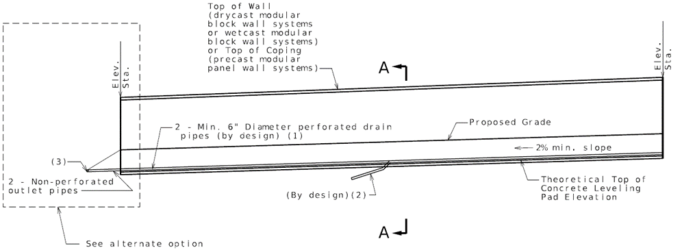 ELEVATION SHOWING DRAIN PIPE
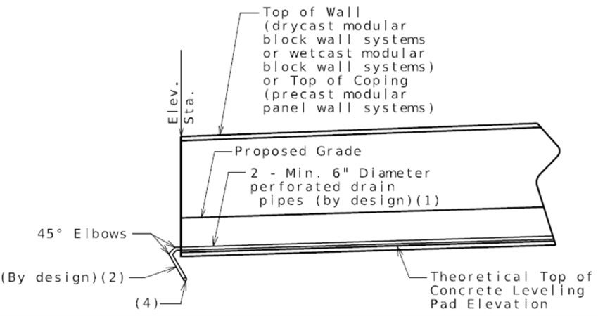 Alternate option

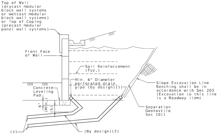 Section A-A