See [https://epg.modot.org/index.php/751.5_Structural_Detailing_Guidelines#751.5.9.2.8_Development_and_Lap_Splices EPG 751.5.9.2.8] for development and lap splice lengths not given or lengths for scenarios other than those shown. Provide standard hooks if required.
See [https://epg.modot.org/index.php/751.5_Structural_Detailing_Guidelines#751.5.9.2.2_Epoxy_Coated_Reinforcement_Requirements EPG 751.5.9.2.2] for epoxy coated reinforcement requirements.
See [https://epg.modot.org/index.php/751.13_Expansion_Devices#751.13.1.4_Details_of_Substructure_Protection EPG 751.13.1.4] for details of protective coating and sloping top of beam to drain when below an expansion device.
620.2.16 Stop and Yield Lines (MUTCD Section 3B.16)
Guidance. Stop lines should be used to indicate the point behind which vehicles are required to stop, in compliance with a traffic control signal.
Option. Stop lines may be used to indicate the point behind which vehicles are required to stop in compliance with a STOP (R1-1) sign, a Stop Here For Pedestrians (R1-5b or R1-5c) sign, or some other traffic control device that requires vehicles to stop, except YIELD signs that are not associated with passive grade crossings.
Yield lines may be used to indicate the point behind which vehicles are required to yield in compliance with a YIELD (R1-2) sign or a Yield Here to Pedestrians (R1-5 or R1-5a) sign.
Standard. Except as provided in MUTCD Section 8B.28, stop lines shall not be used at locations where drivers are required to yield in compliance with a YIELD (R1-2) sign or a Yield Here To Pedestrians (R1-5 or R1-5a) sign or at locations on uncontrolled approaches where drivers are required by State law to yield to pedestrians.
Yield lines shall not be used at locations where drivers are required to stop in compliance with a STOP (R1-1) sign, a Stop Here For Pedestrians (R1-5b or R1-5c) sign, a traffic control signal, or some other traffic control device.
Stop lines shall consist of solid white lines extending across approach lanes to indicate the point at which the stop is intended or required.
Stop lines shall be used in advance of railroad crossings to indicate the appropriate location to stop.
When any crosswalk is installed where a permanent traffic control device is provided, such as a STOP sign or traffic signal, a stop line shall be installed in advance of the crosswalk.
Stop lines shall be 24 in. wide and shall extend across all lanes affected by the traffic control device.
Yield lines shall consist of a row of solid white isosceles triangles pointing toward approaching vehicles extending across approach lanes to indicate the point at which the yield is intended or required. The spacing of triangles in a yield line shall be consistent for that marking.
Guidance. Yield lines should be 24in. wide by 36in. long with 12 in. spacing between triangles, as shown on Standard Plan 620.00. Yield line triangles are paid for per each individual triangle. A yield line, for a lane that is 10 ft. or narrower, will consist of 4 individual triangles spaced accordingly.
Yield lines may also be used where engineering judgment indicates a need.
Guidance. If used, stop and yield lines should be placed a minimum of 4 ft. in advance of the nearest crosswalk line at controlled intersections, except for yield lines at roundabouts as provided for in EPG 620.3.4 Yield Lines for Roundabouts and at midblock crosswalks. In the absence of a marked crosswalk, the stop line or yield line should be placed at the desired stopping or yielding point, but should not be placed more than 30 ft. nor less than 4 ft. from the nearest edge of the intersecting traveled way. Stop lines should be placed to allow sufficient sight distance to all other approaches to an intersection.
When a stop line is used in conjunction with the STOP sign it should be placed adjacent to, or in line with, the STOP sign.
When a yield line is used in conjunction with the YIELD sign it should be placed adjacent to, or in line with, the YIELD sign.
Stop lines at midblock signalized locations should be placed at least 40 ft. in advance of the nearest signal indication.
If yield or stop lines are used at a crosswalk that crosses an uncontrolled multilane approach, the yield lines or stop lines should be placed 20 to 50 ft. in advance of the nearest crosswalk line, and parking should be prohibited in the area between the yield or stop line and the crosswalk (see Figure 620.2.17.1 Examples of Yield Lines at Unsignalized Midblock Crosswalks).
Guidance. Yield (stop) lines and Yield Here To (Stop Here For) Pedestrians signs should not be used in advance of crosswalks that cross an approach to or departure from a roundabout.
Support. Drivers yielding or stopping too close to crosswalks that cross uncontrolled multi-lane approaches place pedestrians at risk by blocking other drivers’ views of pedestrians and by blocking pedestrians’ view of vehicles approaching in the other lanes.
Option. Stop and yield lines may be staggered longitudinally on a lane-by-lane basis. Refer to "D" of Fig. 620.2.8.2.
Support. Staggered stop lines and staggered yield lines can improve the driver's view of pedestrians, provide better sight distance for turning vehicles and increase the turning radius for left-turning vehicles.
620.2.24 Pavement Markings for Highway-Rail Grade Crossings (MUTCD Section 8B.27)
Standard. All grade crossing pavement markings shall be retroreflectorized white. All other markings shall be in accordance with EPG 620 Pavement Marking.
On paved roadways, pavement markings in advance of a grade crossing shall consist of an X, the letters RR, a no-passing zone marking (on two-lane, two-way highways with centerline markings in compliance with EPG 620.2.1), and certain transverse lines as shown in Fig. 620.2.25.1, Example of Placement of Warning Signs and Pavement Markings at Grade Crossings and Fig. 620.2.25.2, Grade Crossing Pavement Markings.
Identical markings shall be placed in each approach lane on all paved approaches to grade crossings where signals or automatic gates are located, and at all other grade crossings where the posted or statutory highway speed is 40 mph or greater.
Pavement markings shall not be required at grade crossings where the posted or statutory highway speed is less than 40 mph if an engineering study indicates that other installed devices provide suitable warning and control. Pavement markings shall not be required at grade crossings in urban areas if an engineering study indicates that other installed devices provide suitable warning and control.
Guidance. When pavement markings are used, a portion of the X symbol should be directly opposite the Grade Crossing Advance Warning sign. The X symbol and letters should be elongated to allow for the low angle at which they will be viewed.
Option. When justified by engineering judgment, supplemental pavement marking symbol(s) may be placed between the Grade Crossing Advance Warning sign and the grade crossing.
620.2.25 Stop and Yield Lines at Highway-Rail Grade Crossings (MUTCD section 8B.28)
Standard. On paved roadways at grade crossings that are equipped with active control devices such as flashing-light signals, gates, or traffic control signals, a stop line (see EPG 620.2.16) shall be installed to indicate the point behind which highway vehicles are or might be required to stop.
Guidance. On paved roadway approaches to passive grade crossings where a STOP sign is installed in conjunction with the Crossbuck sign, a stop line should be installed to indicate the point behind which highway vehicles are required to stop or as near to that point as practical.
If a stop line is used, it should be a transverse line at a right angle to the traveled way and should be placed approximately 8 ft. in advance of the gate (if present), but no closer than 15 ft. in advance of the nearest rail.
Option. On paved roadway approaches to passive grade crossings where a YIELD sign is installed in conjunction with the Crossbuck sign, a yield line (see EPG 620.2.16) or a stop line may be installed to indicate the point behind which highway vehicles are required to yield or stop or as near to that point as practical.
Guidance. If a yield line is used, it should be a transverse line at a right angle to the traveled way and should be placed no closer than 15 ft. in advance of the nearest rail (see Fig. 620.2.25.1, Example of Placement of Warning Signs and Pavement Markings at Grade Crossings).
Fig. 620.2.25.1, Example of Placement of Warning Signs and Pavement Markings at Grade Crossings (MUTCD 8B-6)
Support. Crosswalk markings provide guidance for pedestrians who are crossing roadways by defining and delineating paths on approaches to and within signalized intersections, and on approaches to other intersections where traffic stops.
In conjunction with signs and other measures, crosswalk markings help to alert road users of a designated pedestrian crossing point across roadways at locations that are not controlled by traffic control signals or STOP or YIELD signs.
At non-intersection locations, crosswalk markings legally establish the crosswalk.
Standard. When crosswalk lines are used, they shall consist of solid white lines that mark the crosswalk.
There are two styles of crosswalk markings: transverse and longitudinal (also known as continental). In most applications, the longitudinal markings are preferred and should be used to provide greater visibility, especially at midblock and uncontrolled crossings.
When used, longitudinal crosswalk markings shall be 24 inches wide and at least 6 feet in length, except that they shall be at least 8 feet in length at non-intersection crossings where the posted speed limit is 40 mph or greater.
If used, transverse crosswalk lines shall be no less than 6 inches wide and at least 6 feet apart
Guidance. Crosswalk lines, if used on both sides of the crosswalk, should extend across the full width of pavement or to the edge of the intersecting crosswalk to discourage diagonal walking between crosswalks.
At locations controlled by traffic control signals or on approaches controlled by STOP or YIELD signs, crosswalk lines should be installed where engineering judgment indicates they are needed to direct pedestrians to the proper crossing path(s).
Crosswalk lines should not be used indiscriminately. An engineering study should be performed before a marked crosswalk installed at a location away from a traffic control signal or STOP or YIELD signs. The engineering study should consider the number of lanes, the presence of a median, the distance from adjacent signalized intersections, the pedestrian volumes and delays, the average annual daily traffic (AADT), the posted or statutory speed limit or 85th-percentile speed, the geometry of the location, the possible consolidation of multiple crossing points, the availability of street lighting and other appropriate factors.
New marked crosswalks alone, without other measures designed to reduce traffic speeds, shorten crossing distances, enhance driver awareness of the crossing, and/or provide active warning of pedestrian presence, should not be installed across uncontrolled roadways where the speed limit exceeds 40 mph and either:
A. The roadway has four or more lanes of travel without a raised median or pedestrian refuge island and an ADT of 12,000 vehicles per day or greater; or
B. The roadway has four or more lanes of travel with a raised median or pedestrian refuge island and an ADT of 15,000 vehicles per day or greater.
Support. Chapter 4F of the MUTCD contains information on Pedestrian Hybrid Beacons. Section 4L.03 contains information regarding Warning Beacons to provide active warning of a pedestrian's presence. Section 4N.02 contains information regarding In-Roadway Warning Lights at crosswalks. Chapter 7D contains information regarding school crossing supervision.
Guidance. Because non-intersection pedestrian crossings are generally unexpected by the road user, warning signs (see Non-vehicular Sign (W11-2, W11-7)) should be installed and adequate visibility should be provided by parking prohibitions.
If used, the high-visibility longitudinal pedestrian crosswalk marking should consist of longitudinal bars 24 in. wide and spaced uniformly, centering one bar in each lane, and across each lane line, centerline, and edgeline (see Standard Plan 620.00).
When longitudinal bars are used to mark a crosswalk, the transverse crosswalk lines should be omitted. The marking design should avoid the wheel paths.
Existing 30 in. crosswalk bars should be replaced with 24 in. bars when the roadway is resurfaced.
Support.EPG 620.2.16 contains information regarding placement of stop line markings near crosswalk markings.
Option. Where permanent traffic control devices are not provided, speeds are greater than 35 mph or the crosswalk is located in rural locations where they are unexpected, the width of the crosswalk line may be increased up to 24 inches.
Crosswalks may be located mid-block if this placement offers greater safety to the pedestrian than the normal placement at an intersection. In these cases, the longitudinal bar pedestrian crosswalk marking should be used for greater emphasis and visibility. This type of marking may also be used at locations where substantial numbers of pedestrians cross without any other traffic control device, at locations where physical conditions are such that added visibility of the crosswalk is desired, or at places where a pedestrian crosswalk might not be expected.
Standard. All school crosswalks authorized by an agreement between the Commission and the school and/or city shall be marked. Crosswalks for schools shall be maintained in a manner that will provide a clearly visible marking at all times.
Option. When school crosswalks are located mid-block, the longitudinal bar pedestrian crosswalk marking should be used for greater emphasis and visibility.
Guidance. Crosswalk markings should be located so that the curb ramps are within the extension of the crosswalk markings.
Support. Detectable warning surfaces mark boundaries between pedestrian and vehicular ways where there is no raised curb. Detectable warning surfaces are required by 49 CFR, Part 37 and by the Americans with Disabilities Act (ADA) where curb ramps are constructed at the junction of sidewalks and the roadway, for marked and unmarked crosswalks. Detectable warning surfaces contrast visually with adjacent walking surfaces, either light-on-dark, or dark-on-light. The Americans with Disabilities Act Accessibility Guidelines for Buildings and Facilities (ADAAG) (see MUTCD Section 1A.11) contains specifications for design and placement of detectable warning surfaces.
Fig. 620.2.18, Examples of Crosswalk Markings (MUTCD Figs. 3B-19 and -20)
REVISION REQUEST 3997
616.6.2.2 Flags and Advance Warning Rail System on Signs
Signs may be enhanced with flags, but only during daytime hours. Flags should not be used on signs at night, except that it is allowable to leave flags on signs when the work carries over from day to night.
Standard. When standard orange flags are used in conjunction with signs, they shall not block the sign face.
Example of flag assembly, viewed from behind the temporary sign
616.23.1 Definitions
Activity Area - Area of a temporary traffic control zone where work activity takes place. It is comprised of the work, traffic and buffer spaces.
Advance Warning Area - Area of a temporary traffic control zone where traffic is informed of the upcoming temporary traffic control zone.
Area Lighting - Lighting used at night to guide traffic through the temporary traffic control zone.
Annual Average Daily Traffic (AADT) - Volume of vehicular traffic using a section of highway on an average day.
Barricade - Temporary traffic control device consisting of one or three appropriately marked rails used to close, restrict or delineate all or a portion of the right of way.
Barrier-Mounted Sign - Sign mounted on a temporary or permanent traffic barrier.
Buffer Space - Area within the activity area free of equipment, material, and personnel used to provide lateral and/or longitudinal separation of traffic from the workspace or an unsafe condition.
Channelizer - Temporary traffic control device used to guide traffic or delineate an unsafe condition.
Crash Cushion - Temporary traffic control device used at fixed object and other desirable locations to reduce crash severity.
Daytime/Daylight - Period of time from one-half hour after sunrise to one-half hour before sunset.
Detour - Temporary rerouting of traffic onto an existing facility to avoid a temporary traffic control zone.
Diversion - Rerouting of traffic around an activity area using a temporary roadway or portions of an existing parallel roadway.
Divided Highway - Highway with physical separation of traffic in opposite directions.
Downstream Taper - Visual cue to traffic that access back into a closed lane is available.
Emergency Operation - Work involving the initial response to and repair/removal of safety concerns including Response Priority 1 items.
Fine Sign - Regulatory sign indicating the applicability of additional fines in a temporary traffic control zone.
Flag System – A flag bracket and two flag assemblies. Flags are used to enhance signs.
Flagger - Person who provides temporary traffic control by assigning right of way.
Flashing Arrow Panel - Temporary traffic control device with a pattern of elements capable of flashing displays (i.e. left/right arrow, double arrow, caution mode) used to provide warning or guidance to traffic.
Fleet Lighting
Fleet Lighting - Rotating or flashing lights used to increase the visibility of work-related vehicles and equipment in the temporary traffic control zone.
Guide Sign - Sign showing route designations, destinations, directions, distances, services, points of interest or other geographical, recreational or cultural information.
High Speed - Posted speed of 50 mph and above.
Highway - Any facility constructed for the purposes of moving traffic.
Incident Area - Temporary traffic control zone where temporary traffic control devices are deployed in response to a traffic incident, natural disaster, special event, etc.
Intermediate-Term Stationary Operation - Daytime work occupying a location from more than one daylight period up to 3 days or nighttime work occupying a location more than 60 minutes.
Lane Taper - Temporary traffic control measure used to merge or shift traffic either left or right out of a closed lane.
Lateral Buffer Space - Obstacle-free area adjacent to the workspace or an unsafe condition that provides room for recovery of an errant vehicle.
Lighting Device - Temporary traffic control device illuminating a portion of the roadway or supplementing other traffic control devices.
Long-Term Stationary Operation - Work occupying a location longer than 3 days.
Longitudinal Buffer Space - Obstacle-free area in advance of the work space or an unsafe condition that provides room for recovery of an errant vehicle.
Low Speed - Posted speed of 45 mph and below.
Low Volume - 500 or less AADT. The rule of thumb is to count the number of vehicles passing a single reference point over a five-minute period. If not more than three vehicles pass the reference point in that period, then the road can be considered low volume for the purpose of installing work zone traffic control.
May - Indicates a permitted practice and carries no requirement or recommendation.
Mobile Operation - Work on the roadway that moves intermittently or continuously.
Motorized Traffic - Movement of vehicles and equipment on the roadway.
Multilane Highway - Highway with two or more driving lanes in the same direction of travel.
Nighttime - Period of time from one-half hour before sunset to one-half hour after sunrise.
Non-Motorized Traffic - Movement of pedestrians, bicycles, horse-drawn vehicles, etc. on roadway or within the right of way.
One-Lane, Two-Way Taper - Temporary traffic control measure used to channelize traffic through an activity area occupying one lane of an undivided, two-lane roadway.
Pavement Marking - Lines, markers, words and symbols affixed to the pavement surface to channelize and guide traffic.
Pilot Car - Vehicle used to guide a queue of vehicles through the temporary traffic control zone.
Portable Sign - Sign mounted on temporary supports (e.g. self-driving post, easels, foldup stands, barricades, etc.).
Post-Mounted Sign - Sign mounted on a non-portable post (e.g. perforated square steel tube, u-channel, wood, etc.).
Protective Vehicle - Vehicle used to protect workers or work equipment from errant vehicles (e.g. pick up, dump truck, loader, etc.).
Regulatory Sign - Sign giving notice of traffic laws or regulations.
Roadway - Portion of highway, including shoulders, intended for use by motorized traffic.
Rural - Area generally characterized by lower volumes, higher speeds and fewer turning conflicts and conflicts with pedestrians. Includes unincorporated areas designated by community boards.
Shall - Indicates a required, mandatory, or specifically prohibitive practice. Shall statements are not to be modified or compromised based on engineering judgement or engineering study.
Short Duration Operation - Daytime or nighttime work occupying a location up to 60 minutes.
Short-Term Stationary Operation - Daytime work occupying a location more than 60 minutes, but less than 12 hours.
Should - Indicates a recommended, but not mandatory, practice in typical situations. Deviations are allowed if engineering judgement or engineering study indicates the deviation to be appropriate.
Shoulder Taper - Temporary traffic control measure used to close the shoulder.
Sign - Traffic control device conveying a static message to traffic through words or symbols.
Speed Limit - Maximum speed applicable to a section of highway as established by law.
Stop Bar - Solid white pavement marking extending across an approach lane to indicate the point where traffic is to stop.
Supplemental Warning Methods - Temporary traffic control enhancements used to increase the effectiveness of select temporary traffic control devices or the awareness of the entire temporary traffic control zone.
Taper - Series of channelizers and/or pavement markings used to move traffic into the intended path.
Temporary Traffic Barrier - Temporary traffic control device used to create a physical separation between traffic and the workspace, an unsafe condition, or non-motorized traffic.
Temporary Traffic Control Device - Item used to regulate, warn or guide traffic through a temporary traffic control zone.
Temporary Traffic Control Plan - Describes temporary traffic control measures to be used for moving traffic through a temporary traffic control zone.
Temporary Traffic Control Signal - Temporary traffic control device used to assign right of way through automatic means.
Temporary Traffic Control Zone - Section of highway where traffic conditions are changed due to a work zone or an incident area through the use of temporary traffic control devices, law enforcement or other authorized officials. It extends from the first warning sign or rotating/strobe lights on a vehicle to the last temporary traffic control device.
Termination Area - Area of a temporary traffic control zone returning traffic to the normal path.
Traffic - Highway user.
Traffic Space - Area within the activity area in which traffic is routed through the activity area.
Transition Area - Area of a temporary traffic control zone where traffic is redirected out of the normal path and into the traffic space.
Traveled Way - Portion of roadway intended for the movement of motorized traffic.
Truck-Mounted Attenuator (TMA) - Device designed to attach to the rear of protective vehicles to absorb the impact of an errant vehicle or inattentive driver.
Undivided Highway - Highway with no physical separation of traffic in opposite directions.
Urban - Area within the limits of incorporated towns and cities where the posted speed is 60 mph or less.
Vehicle-Mounted Sign - Sign mounted on a protective vehicle used in short duration and mobile operations or on a pilot car.
Warning Sign - Sign giving notice of a situation or condition that might not be readily apparent.
Work Duration - Length of time an operation occupies a location.
Work Lighting - Lighting used at night to perform activities within the workspace.
Work Location - Portion of right of way in which work is performed.
Workspace - Area within the activity area closed to traffic and set aside for workers, equipment, materials and a protective vehicle, if one is used upstream. Channelizers usually delineate workspaces.
Work Vehicle - Any vehicle by which work is performed.
Work Zone - Temporary traffic control zone where temporary traffic control devices are deployed for construction, maintenance or utility- related work activities.
Work Zone Length - Distance from last sign in the advance warning area to the last temporary traffic control device in the same direction or the last sign in the advance warning area in the opposing direction, whichever is longest.
Refer to EPG 902.18 Glossary for definitions of interchange, intersection and right of way.
Flags may be used to supplement these signs provided they do not block the sign face. Additional information located in EPG 616.6.2.2 Flags.
UPLOAD NEW IMAGES
616.19.2.2.2 Sign and Flag Quality
Acceptable Examples
(1)
(2)
(3)
The signs in Pictures 1, 2 and 3 are considered in good quality. Supplemental devices such as flags and/or a cone may be placed next to a sign. Picture 2 is an example of the proper placement of a FLAGGER (WO20-7) sign, with the optional flags, in advance of the hill versus after the hill. In urban areas with barrier walls and narrow shoulders, a truncated sign may be used as shown in Picture 3.
Note: TTCDs may be highly visible during the day but may not be at night due to inadequate retroreflectivity. MoDOT and Contractor representatives should drive through the work zone at night to check nighttime visibility.
Unacceptable Examples
(4)
(5)
(6)
(7)
(8)
(9)
Pictures 4-7 are in unacceptable condition. Dirty or damaged signs should be cleaned, repaired, or replaced before being installed. When cleaning, follow manufacturer’s recommendations, so the daytime and nighttime visibility of the sign is not adversely impacted. The MEN WORKING sign (Picture 8) should be replaced with worker symbol sign or WORKERS sign (WO-21-1 or 1a) to meet current standards. Picture 9 shows unacceptable flags, if used, deteriorated flags should be replaced.
Unacceptable Examples
(10)
(11)
(12)
(13)
Pictures 10 - 13 are examples of unacceptable nighttime visibility. Proper storing, transporting, and covering signs is crucial to minimizing deficiencies.
REVISION REQUEST 4008
403.1.5 Mixture Production Specification Limits (Sec 403.5)
Intentional deviations from the JMF will not be permitted, except under the conditions set forth in Sec 403.11. The plant shall be operated in such a manner that the mix is produced as shown on the JMF. The specification tolerances are developed in an attempt to keep the mix as consistent as possible and to allow for some variation during production. However, these tolerances are not production limits. For example, if the target binder content is 5.0%, the binder content of the mix can range from 4.7% to 5.3% when the tolerances are applied. The contractor will not be allowed to produce the mix at 4.7% to save money.
Operating out of the specifications may reduce the contractor's pay and/or the pavement service life. When QC tests, either random or informational, are out of specification tolerances, the contractor should adjust the production to bring the mix back in. When QA tests are out of specification tolerances, the contractor should be notified immediately. The contractor is responsible for deciding when adjustments are made to control the mix. Some test properties may be allowed to deviate beyond specification limits occasionally, provided that adjustments are made and the following tests show that production is back within limits.
Production may be required to cease if the random QC or QA test results are either out of specifications far enough to indicate that the mix may be subject to failure or beyond the specification removal limits. Production should cease until verification that the problem has been corrected. An order record should be written, on the same day or the next day if paving occurs at night, describing the deficiency and the location and amount of mix affected. The contractor may elect to continue production in order to run more tests. If so, the order record should state that any mix produced after the order record was issued is at the contractor’s risk. Final disposition of the mix can then be made based on all tests and observations and may consist of acceptance at a reduced price or removal and replacement of unacceptable material.
Both QC and QA will use the following procedures to determine volumetrics of the mix and compliance with Standard Specification Sections 403.5.3 through 403.5.5. These procedures are discussed in greater detail in the Levels 1 and 2 Bituminous Training.
In situations where a retained sample must be tested, the following procedure should be used to reheat the sample. Heat the sample in an oven until the mix is workable. Take the mix out of the sample container (box, bucket, etc.) and spread it in a large pan or several smaller pans. Using this procedure, the mix will reach the molding temperature much quicker than it would if it were left in a mass in the sample container. Also, less aging of the mix occurs since the mix is in the oven for a shorter period of time. Once the mix has reached an acceptable temperature, quarter split the mix. The split portions to be used for making gyratory specimens shall then be heated to the compaction temperature. The entire suite of tests must be performed on a retained sample.
Gradation (Sec 403.5.1)
See Sieve Analysis in Plant Inspection. The gradation of the mix
is not a pay factor item. However, it does have a significant influence on the volumetrics of the mix. Samples may be taken from the hot bins at a batch plant or from the combined cold feed at a drum plant. It is acceptable to determine gradation from the binder ignition sample according to AASHTO Standard Test Method T 308. Contractors should be allowed the option provided that the chosen method is spelled out in the Quality Control Plan. Gradations of extracted samples would be satisfactory as well. QC is required to sample the aggregate and perform a sieve analysis twice per lot. QA is required to independently sample the aggregate and perform a sieve analysis once per lot. These testing requirements are minimums and should be increased as necessary. Minor deviations outside the tolerances given in Standard Specification Sections 403.5.1.1 or 403.5.1.2, whichever is applicable, may be allowed if the test results indicate that the binder content, volumetrics, and density of the mix are satisfactory. If the test results are unsatisfactory, adjustments of the JMF, in accordance with Standard Specification Section 403.11, are necessary.
Stone Matrix Asphalt Tolerances (Sec 403.5.1.1)
The tolerances from the JMF for SMA mixes are given in Standard Specification Section 403.5.1.1.
Mixture Tolerance (Sec 403.5.1.2)
During production, the combined aggregate gradation must be within the following limits:
Percent Passing by Weight
Sieve Size
SP250
SP190
SP125
1 ½ in.
100
--
--
1 in.
90-100
100
--
¾ in.
92 Max.
90-100
100
½ in.
--
92 Max.
90-100
3/8 in.
--
--
92 Max.
#4
--
--
--
#8
17-47
21-51
26-60
#16
--
--
--
#30
--
--
--
#50
--
--
--
#100
--
--
--
#200
1-7
2-8
2-10
Density (Sec 403.5.2)
See also Density in Plant Inspection Density Samples in Paving Operations. One sample per sublot will be taken for QC testing. QA will randomly test one of the samples from each lot to verify that a favorable comparison is obtained. These testing requirements are minimums and should be increased as necessary. SMA mixes shall have a minimum density of 94.0% with no upper limit. All other mixes shall have a density of 94.0 ±2.0%.
Shoulder Density (Sec 403.5.2.1) and Integral Shoulder (Sec 403.5.2.2)
If the shoulders and the traveled way are placed in the same pass (integrally), the cores will be taken on the traveled way. No cores will be taken on the shoulder. For example, if the paving width is 16’ with a 12’ travel lane and a 4’ shoulder, the shoulder will not be subject to density testing.
Asphalt Content (Sec 403.5.3)
QC is required to sample and test the mix for the binder content once per sublot and QA is
required to independently sample and test the mix once per lot. These testing requirements are
minimums and should be increased as necessary. During production, the binder content of the
mix, as determined by sampling and testing, shall be within ±0.3% of the target listed on the JMF.
Voids in the Mineral Aggregate (VMA) (Sec 403.5.4)
QC is required to sample and test the mix for the VMA once per sublot and QA is required
to independently sample and test the mix once per lot. These testing requirements are minimums
and should be increased as necessary. The VMA of the mix shall be within –0.5% and +2.0% of
the minimum required for the corresponding mix type (see Standard Specification Section 403.4.6.2).
The following table gives the ranges for each mix type:
Mix Type
VMA Limits (percent)
SP250
11.5-14.0
SP190
12.5-15.0
SP125
13.5-16.0
SP095
14.5-17.0
SP048
15.5-18.0
SMA
16.5-19.0
Air Voids (Va) (Sec 403.5.5)
QC is required to sample and test the mix for the air voids once per sublot and QA is
required to independently sample and test the mix once per lot. These testing requirements are
minimums and should be increased as necessary. The Va for all mixes shall be 4.0 ±1.0%.
Tensile Strength Ratio (TSR) (Sec 403.5.6)
The TSR is used to evaluate the impact that water saturation and freeze-thaw cycles have on the strength of an asphalt mix. It can also be used to predict the susceptibility of the mix to
stripping.
During production, loose mix samples will be taken and quartered as described in Mixture Production Specification Limits. TSR samples need to be taken from random locations. However, they should be taken whenever it is convenient to production, such as during a big gap between QC volumetric tests. By specification, sampling locations are from the roadway behind the paver, however, should the MoDOT inspector deem this an unsafe or impractical location, the sample may be taken from the plant. The QA sample(s) should be taken from the same point as the QC sample(s). If QC takes their sample from the plant, QA should take their sample from the plant also. This does not mean that QA should be taking their samples at the same time as QC. Two opposite quarters will be retained and the remaining two quarters will be mixed together and tested in accordance with AASHTO T283.
QC should obtain enough mix to retain a sample. QC will sample and test each mix at a minimum of once every 10,000 tons, or fraction thereof. QA will independently sample and test each mix at a minimum of once every 50,000 tons. The TSR sampling requirements are best described with an example. Suppose that 112,960 tons of SP190 are to be placed on a project. By specification, QC is required to take twelve samples and QA is required to take three samples. There are two possible scenarios for sampling this mix. QC may take eleven samples representing 10,000 tons each and a twelfth sample that represents the remaining 2,960 tons. Or QC may take ten samples that represent 10,000 tons each and two samples that represent the remaining 12,960 tons (6,480 tons each). Either scenario is acceptable. Likewise, QA may take two samples representing 50,000 tons each and a third sample that represents the remaining 12,960 tons. Or QA may take one sample that represents 50,000 tons and two samples that represent the remaining 62,960 tons (31,480 tons each). The contract quantity may be used to approximate sample 1 locations.
MoDOT should collect at least 250 pounds of asphalt mix for the QA sample, 125 pounds is retained by the RE and the other 125 pounds is sent to the Central Laboratory (typically) in 4 – 13” x 13” x 4.5” boxes for QA testing. Each box must be labeled on one side with the AASHTOWARE Project (AWP) ID, Mix Type, VMA Limits (percent) number and the mix number. An AWP record must be created for each sample, which must include all required information, the mix number, sample date, and the represented tonnage. The represented tonnage is explained in the example in the preceding paragraph. It is recommended to include the lot and sublot to the AWP record as additional information.
Additional information that may be included in the AWP record is the Gmm from the sublot that the sample was taken in (QC or QA) and the specimen weight that QC has been using. The specimen weight may be different from that shown on the JMF because of bin percent changes, etc. This information is helpful because it results in less trial-and-error for the Central Laboratory.
In the laboratory, a minimum of six specimens are compacted to a height of approximately 95 mm. The air voids of the specimens are calculated. For all mixes other than SMA, the air voids must be within 7.0 ±0.5%. For SMA mixes, the air voids must be within 6.0 ±0.5%. Half of these specimens are saturated, frozen, and thawed. These are the conditioned specimens. The degree of saturation of the conditioned specimens is also calculated. The remaining specimens are unconditioned. Then, the indirect-tensile strength of all of the specimens is determined. Therefore, the TSR is the ratio of the average tensile strength of the conditioned specimens to the average tensile strength of the unconditioned specimens.
A favorable comparison will be obtained if the QC and QA test results are within 10% of each other. The contractor’s pay will be adjusted in accordance with Standard Specification Section 403.23.5 based on the QC test results. For example, if the QC TSR is 95% and the QA TSR is 93%, a favorable comparison has been obtained and the contractor will receive a 3% bonus. However, if the difference is greater than 10%, the field office should be consulted. The field office will evaluate the air voids and saturation levels. The raw data should be collected from QC and forwarded to the field office for comparison in order to determine whether it will be necessary to proceed with 3rd party testing. QC and QA retained samples should be kept for an extended period of time so that they may be used during dispute resolution, if necessary.
The QC data should be reported in AWP (Test - SAA402AB). Contractors may report their own test results using the TSR Contractor Reporting Excel to Oracle Spreadsheet available on the MoDOT Quality Management website. Furthermore, this information is quarried regularly and, provided that a favorable comparison is reached, used to signal the appropriate time for disposal of the remaining TSR sample at the Central Lab.
Aggregate Properties (Sec 403.5.7)
The aggregate consensus tests (Fine and Coarse Aggregate Angularity, Clay Content, and Thin, Elongated Particles) are performed on the blended aggregate. The aggregate will be sampled from the combined cold feed whether dealing with a drum-mix plant or a batch plant. Aggregate samples should be taken in accordance with AASHTO R 90.
For each mix that is produced, QC shall sample the aggregate and perform the consensus tests once every 10,000 tons with a minimum of one per mix per project. QA will independently sample the aggregate and perform the consensus tests once per project. QA should also test a minimum of one QC retained sample per project. For large projects, enough QC retained samples should be tested to ensure that QC is performing the tests correctly. These testing requirements are minimums and should be increased as necessary. During production, the following tolerances are applied (see Standard Specification Sections 403.2.1 through 403.2.5 and Consensus Testing).
Under QC/QA, the contractor performs quality control (QC) testing. The contractor is paid based on the results of the randomly located QC tests for Superpave mixes. Beyond random QC tests, quality control by the contractor consists of constantly monitoring materials integrity, mix production and laydown operations to ensure overall acceptability.
Asphalt Test Results (Sec 403.17.1.1)
A copy of all random QC test results shall be furnished to the QA inspector no later than the beginning of the day after testing has been performed. All raw data and printouts must be included with the testing records. Raw data consists of all weights, measurements, etc. used to arrive at the final test results. Printouts include the gyration/height data from the gyratory compactor and the asphalt content ticket from the binder ignition oven or nuclear gauge. The QC testing records must be made available to the QA inspector at all times.
It is QC’s responsibility to take appropriate action if unsatisfactory mix is being produced. This may include making adjustments to the plant to bring the mix back into specification, sampling the mix from the roadway and performing informational testing, removing mix from the roadway, etc.
Informational Tests
An informational test is a test that QC may perform between random testing to determine whether or not the mix is within specifications. Informational testing is not required and may be performed at any time and at any frequency. Generally, informational testing will be performed early in the production period. The informational test may not be completed in full. For example, QC may only compact the gyratory specimens. Doing so will yield specimen heights and the contractor may or may not make production adjustments based on these heights. Informational test samples must be clearly marked as such if they are tested and stored in the field laboratory.
QC is not required to provide the QA inspector with informational test results, since informational tests cannot be used in the QC process to determine pay factors, The timing of random number locations being given to the contractor, typically 100 to 150 tons in advance, is meant to protect the integrity of the statistical sampling process. QA always has the option of taking its own informational samples.
Informational test data may be used to determine asphalt removal limits if it is adequately documented. It should not be used for QLA under any circumstances. To be considered adequately documented the following criteria should be met:
The gyratory pucks should be clearly identified and labeled and made available for verification.
The gyratory printout should be available.
The printout from the AC test should be available.
If the preceding conditions are met and the gyratory specimens are used to troubleshoot the placement, the specimens can then be weighed and bulked to determine the volumetric properties. Data from informational tests is approximate. Its only legitimate use to the QA inspector is to help determine the point on the roadway where the mixture transitioned either above or below the removal limits. We don’t want to remove acceptable mix or leave unacceptable mix in place.
Removal Limits
As an example of how informational tests may be used to designate removal limits of failing QC samples, the following situation is provided. The random QC sample shown in the diagram below fell late in sublot ‘a’ and test results indicated that voids were below the limits for removal. By specification sublot ‘a’ should be removed. By the time the test results were available and corrective action was taken, the contractor had crossed into sublot ‘b’. Assuming that mix properties were acceptable at the beginning of sublot ‘a’, the actual limits of unacceptable material are indicated by the dashed lines.
Adhering strictly to the specification, it is likely that acceptable material early in sublot ‘a’ will be removed, and it is also likely that unacceptable material early in sublot ‘b’ will be left in place. An adequately documented informational test may be used to zero in on the transitions out of, and back into, acceptable mix. It doesn’t matter that the data is approximate, only that it is above the limit for removal.
Random tests within removal limits are to be replaced by an equal number of random QC test locations, regardless of tonnage. For example, if 750 tons replace an area covered by two random tests, the new tests would be randomly chosen in each 375 ton portion of the replaced mixture.
The resident engineer has the option to determine removal limits based on puck height, provided that the informational test data is consistent with previous production.
When the random QC density core is below or above the removal limits, additional cores may be cut using the following procedure to determine the area of removal. Locations 250’ parallel to the centerline, ahead and back of the failing QC location, will be determined by the engineer. Cores will be cut in these locations and tested. If both sets of cores are not below or above the removal limits, the 500’ section will be removed and replaced with acceptable material and a new random QC core will be cut with-in the new pavement. If either set of the cores are below or above the removal limits, the whole sublot or the area in which the density core represents is subject to removal.
Any sublot of material with air voids in the compacted specimens less than 2.5 percent shall be evaluated with Hamburg testing and removed and replaced with acceptable material by the contractor if the rut depth is greater than 14.0 mm.
Inertial Profiler Test Results (Sec 610)
Surface of the pavement should be thoroughly tested with an inertial profiler or straightedge as required by Sec 610. The procedures for testing with an inertial profiler and analyzing the results with the ProVAL software program are set forth in EPG 106.3.2.59 TM-59, Determination of the International Roughness Index.
Bituminous Quality Control Plan (Sec 403.17.2)
The contractor documents the QC method with a quality control plan (QC Plan*). The QC plan for Superpave mixes shall include the contact information of the contractor’s QC representative, lot and sublot sizes and how they will be designated, the test method for determining asphalt binder content, the number of cores to be cut for density determination, and the independent third party for dispute resolution. The QC plan is approved by MoDOT Construction and Materials and used as a contract document during mix production. Contractor technicians who perform materials testing shall be certified through the MoDOT Technician Certification Program (TCP).
Note*: A QC Plan is not required for bituminous base (BB) and pavement (BP) mixes.
Up to 3 cores are allowed at each random location, but only if spelled out in the QC plan. In the drawing below, the cylinder represents the station and offset of the random location. Best management practice is for QA to mark that location on the pavement. The first density core should have that marking on it. Any additional cores should be taken along a straight line, parallel to the centerline, within 1 foot either side of the random location.
QC must retain the portion of each sample that is not tested after the sample has been reduced to testing size. This includes gradation, consensus, TSR, and volumetrics samples. The retained samples must be clearly identified in accordance with Standard Specification Section 403.17.2.3 and stored in the field laboratory for a minimum of 7 days. Also, all cores must be retained for a minimum of 7 days. Notwithstanding the 7 day minimum, retained samples should not be discarded until all comparison issues with the lot are resolved. If space at the field lab is an issue, the sample should be stored at the project office.
There is no legitimate reason for unidentified samples to be in the field laboratory. The QA inspector should insist that all test specimens in the field laboratory be marked as soon as they are cool enough. The identifying mark should be permanent, unique, and indicate what the sample is.
When running a QC split sample, the comparisons should be within the tolerances shown in the following table:
Loose Mix Property
Tolerance
Gmb
0.010
Gmm
0.010
AC %
0.1%
Gradation Sample (Sec 403.17.2.3.1)
QC will retain the portion of their gradation sample that is not tested. This includes the sample of the combined cold feed from a drum plant and all hot bin samples from a batch plant. Aggregate samples should be taken in accordance with AASHTO R 90.
Loose Mix Sample (Sec 403.17.2.3.2)
A loose mix sample consisting of roughly 100 lbs. will be taken from the roadway behind the paver, in accordance with AASHTO T168, at the required frequency. The sample will be thoroughly mixed and quartered in accordance with AASHTO R47, or with an approved splitting/quartering device. Two opposite quarters will be retained for testing during the dispute resolution process, if necessary. The remaining two quarters will be mixed together and quartered again.
The required weight of mix, as listed on the JMF, will be taken from one quarter and used to compact a specimen in accordance with AASHTO T312. The mix will be compacted to Ndes gyrations while the mix temperature is within the molding range listed on the JMF. Using the opposite quarter, follow the same procedure for the second specimen. The Gmb of each specimen will be determined and the average will be used to calculate the air voids Va and the voids in the mineral aggregate (VMA). By specification, a minimum of two compacted specimens must be used to calculate these properties.
A third quarter will be used to determine the Gmm of the mix in accordance with AASHTO T209. The minimum sample size for each type of mix can be found in the training manual. This property is used to calculate the Va and density. The volume of the sample, which is needed in the calculation, can be determined by either the weigh-in-air method or the weigh-in-water method. The weigh-in-air method consists of weighing the sample and container (with the lid) completely filled with water in air. The weigh-in-water method consists of weighing the sample and container (without the lid) completely submerged in water.
The remaining mix should be mixed together and quartered again. To determine the binder content using the nuclear gauge, enough mix should be taken from opposite quarters. The required weight of mix is listed on the JMF. A moisture content sample should be taken from the same quarters. To determine the binder content using the binder ignition oven, enough mix should be taken from one quarter. The minimum sample size for each type of mix can be found in the training manual. A moisture content sample should be taken from the same quarter. Sometimes the ignition oven may not shut itself off. The oven may be shut off manually as long as 3 consecutive readings show less than 0.01% loss. The sample should be examined to assure that a complete burn has been achieved. This will be considered a valid test.
Quality Control Laboratory (Sec 403.17.3)
The contractor is required to provide an appropriately equipped QC laboratory, however, it is not required to be at the plant. The contractor is also required to provide office space at the asphalt plant for the QA inspector to work on records and reports. Usually, these two requirements are met with one structure, but not always. The intent of the specification will be met if the QA inspector is provided with suitable facilities at the plant, but the lab is located offsite at another location, such as between the jobsite and the plant. The laboratory should have internet access in the event that cell phone service is not available.
Calibration Schedule (Sec 403.17.3.1)
Calibrations and verifications of the testing equipment are very important. If the equipment has not been calibrated or verified as required, false test results may be obtained. The maximum intervals are given in Standard Specification Section 403.17.3.1. These frequencies are taken from the AASHTO test methods and/or the manufacturer’s recommendations.
Calibration Records (Sec 403.17.3.1.2)
Periodically, the QA inspector should check the QC calibration records to ensure that the equipment has been calibrated or verified in accordance with Standard Specification Section 403.17.3.1.
REVISION REQUEST 4009
502.1.11 Contractor Quality Control (Sec 502.11)
Gradation and Deleterious Material (Sec 502.11.2.1.1)
Aggregate Sampling Hints:
Bin Discharge
Ensure sampling device cuts entire stream of material
Do not over fill the sample device
Ensure sampling device is cleaned out
Plant operating at usual production rates
Obtain 3 or more equal increments
Use AASHTO R 90
Belt
Sample template fits the belt
Sweep all the fines from the belt
Obtain 3 or more increments
Ensure that the contractor is aware that a belt sample is being obtained
Ensure that template is pushed all the all the way to the belt
Use air-tight container to prevent moisture loss prior to testing
Slump (Sec 502.11.2.2)
Slump Testing Hints
Perform test within 2 1/2 minutes
Fill mold in 3 equal volumes
Do not use rebar as tamper rod
Perform on level ground
Pre-wet equipment before testing
Lift mold straight up
Rod concrete properly
Entrained Air Content (Sec 502.11.2.3)
Air Content Testing Hints
Rod concrete properly
Fill mold in 3 equal layers
Perform on level ground
Do not use rebar as tamping rod
Use aggregate correction factor
Tap sides of bowl after each layer
Pre-wet equipment before testing
Use calibrated equipment
REVISION REQUEST 4020
501.1.6 Measurement of Material (Sec 501.6)
501.1.6.1 Mass Determination (Sec 501.6.1)
The plant inspector must assure that all equipment is of an approved design and that all
installations meet requirements of the specifications. There must be no attachments to scales or
weighing hoppers which might hamper free movement of any part of the weighing mechanism, or
cause inaccurate weighing during actual operation of the equipment.
501.1.6.2 Mixing Water (Sec 501.6.2)
Control of the amount of water added to the batch at the concrete mixer is a highly important
part of the proportioning process. This is true whether water is being added through a paving
mixer or is being added to central or truck mixed concrete at the plant. The inspector should be
acquainted with the mechanical operation and construction of the water system. All joints should
be water tight and all valves should close tightly. Leakage of water into the mixer before or after the measuring tank has been discharged should not be permitted.
501.1.6.3 Scale Calibration (Sec 501.6.3)
Scales may be calibrated in the following manner: Balance the scales accurately with no load. Use standard test weights for the test load. Test weights are suspended from the weighing hopper in such a manner that the test load is uniformly distributed. Load the aggregate scales, using combinations of weights totaling approximately 2000 pounds with test weights as required by Sec 501 of the Standard Specifications, and record scale reading. Remove weights and draw 2000 pounds of aggregate equal to the test load from the bins into the weighing hopper. Apply 2000 pounds of standard weights and record scale reading again. Repeat this procedure of drawing up aggregate, adding test weights, and recording scale weights until each scale has been calibrated to a load approximately 5% greater than the maximum working load. Cement scales should be calibrated in the same manner with approximately 500 pounds of test weights. Aggregate or cement scales may be calibrated using different weight increments, if approved by the engineer.
PCC pavement plants should be calibrated before actual proportioning starts from any new plant set up. Scale verification by the contractor or producer shall occur six months after the last plant calibration.
Calibration for other than PCC pavement plants should be at the start of the construction season. Plants located in urban areas may require more frequent calibration. Verification is required to determine if any wear and tear on the weighing equipment has occurred during the previous six months.
Check sensitivity of the scale during the calibration test by applying a small weight and observing movement of the indicator. For aggregate scales, this weight should be 5 pounds and for cement scales, 2 pounds or less. In any case, the sensitivity weight should not be greater than 0.1% of the nominal capacity of the scale. Movement on the indicator should be sufficient to indicate that the scale is out of balance.
Check the balance of each scale assembly with all weigh beams in the system free and the weight indicator counterweights moved to zero.
The inspector should check scales for balance and sensitivity of each scale assembly at random at least twice each day. These checks should be noted in the diary.
Verification of weighing equipment will consist of balancing the scales and then loading the scale to approximately 250 pounds below the scale setting, then adding approximately 500 pounds of standard test weight in not more than 150 pound increments to bring the scale to approximately 250 pounds over the scale setting.
These weight intervals for calibration, verification, balance and sensitivity are considered to be the maximum. If difficulty is encountered with the batching operation or if any of the aforementioned checks indicate excessive deviations, the plant should be recalibrated to ensure compliance.
Sec 502.4.5 of the Standard Specifications sets out certain conditions under which automatic batching equipment must be furnished. In addition to calibration procedures, automatic equipment must be checked for compliance with requirements of Sec 502.4.5 of the Standard Specifications. It is particularly important to ascertain that the discharge
mechanism will not operate when ingredients have not been weighed within specified tolerances.
This check can be made by adding or removing a weight slightly greater than the permissible tolerance to see if the discharge mechanism locks and appropriate warning is given, such as a light buzzer.
In the case of a breakdown in equipment which requires a shift to manual operation, the time of breakdown should be noted in the inspector's diary. The contractor should be promptly advised of the limitation for manual batching.
Water Measuring Devices. Control of the amount of water added to the batch at the concrete
mixer is a highly important part of the proportioning process. This is true whether water is
being added through a paving mixer or is being added to central or truck mixed concrete at the
plant. The inspector should be acquainted with the mechanical operation and construction of the
water system. All joints should be water tight and all valves should close tightly. Leakage of
water into the mixer before or after the measuring tank has been discharged should not be permitted.
Inspection and calibration of the water system should be performed with utmost care and thoroughness. The water measuring device must be calibrated to determine accuracy of measurements. The most common type of measuring device consists of a tank which may be emptied to various levels by adjusting the height of a movable discharge pipe inside the tank. These devices should be calibrated by weighing the amount of water discharged at various settings on the gauge dial. On some installations water may be weighed, in which case, it will be necessary to calibrate the weighing device by using standard weights. Operation of the water system during calibration should be similar to operating conditions. The full range of water measurements required during mixing operations should be covered during calibration. Several checks should be made at various settings to determine if the device will consistently measure the correct quantity within the permissible tolerances allowed by Sec 501.6 of the Standard Specifications. The water meter will be verified at the same frequency as the weighing equipment. At least one setting shall be verified within the working range.
Admixture Dispensers. All measuring devices for dispensing of admixtures should also be carefully checked. The admixture dispensers shall be calibrated by a commercial scale company,
the admixture company or the concrete plant company. Admixture dispensers are usually checked by causing the dispenser to discharge into a graduate where the quantity may be accurately
measured. Repeated measurements should establish that the dispenser will operate within
tolerances permitted by the Standard Specifications. Results of all calibrations, verifications, and sensitivity checks should be made a part of the permanent records. Whenever the admixture dispenser is in question, the inspector has the authority to verify the dispenser.
Development lengths for tension reinforcement shall be calculated in accordance with LRFD 5.10.8.2.1.
Excess reinforcement modification factor (λer) and beneficial clamping stresses (βt component of λrc) of LRFD 5.10.8.2.1c may be used in situations where development length is difficult to attain. All other modification factors shall be used.
Temperature and shrinkage reinforcement are assumed to fully develop the specified yield stresses. Therefore the development length shall not be reduced by λer .
Development lengths for tension reinforcement have been tabulated on the following pages and include the modification factors except as described above.
Lap Splices of Tension Reinforcement (Straight and Hooked)
Lap splice lengths for tension reinforcement shall be calculated in accordance with LRFD 5.10.8.4.2a and 5.10.8.4.3a. Class B splices are preferred when possible, however it is permissible to use Class A when physical space is limited and Class A requirements are met. It should be noted that "required by analysis" of the Class A requirements is based on the stress encountered at the splice location, which is not necessarily the maximum stress used to design the reinforcement. Lap splice lengths for tension reinforcement have been tabulated on the following pages and include the development length modification factors as described above.
Development of Hooked Tension Reinforcement
Development lengths of hooked tension reinforcement shall be calculated in accordance with LRFD 5.10.8.2.4.
Excess reinforcement modification (λer) and beneficial clamping stresses (βt component of λrc) of LRFD 5.10.8.2.1c may be used in situations where development length is difficult to attain. The permissible 20 percent reduction of LRFD 5.10.8.2.4c may be used in situations where development length is difficult to attain and where required conditions are met. All other modification factors shall be used.
Development lengths of hooked tension reinforcement have been tabulated on the following pages and include the modification factors except as described above.
Development of Compression Reinforcement
Development lengths for compression reinforcement shall be calculated in accordance with LRFD 5.10.8.2.2.
Excess reinforcement modification factor (λer) of LRFD 5.10.8.2.2b may be used in situations where development length is difficult to attain. All other modification factors shall be used.
Development lengths for compression reinforcement have been tabulated on the following pages and include the modification factors except as described above.
Lap Splices of Compression Reinforcement
Lap splices lengths for compression reinforcement shall be calculated in accordance with LRFD 5.10.8.4.2a and 5.10.8.4.5a.
Splice lengths for compression reinforcement have been tabulated on the following pages.
751.5.9.2.8.2 Development and Lap Splices of Straight Deformed Bars in Tension
The values in the following table are based on Grade 60 bars (ƒy = 60 ksi) and may be adjusted for yield strengths up to 100 ksi. The final step in the table adjusts values for other material strengths. The values for Grade 40 bars are 45% (402/602) of the values in the table (not less than 12 inches), and values for 280% 100 ksi bars are (1002/602) of the values in the table.
751.5.9.2.8.3 Development and Lap Splices of Deformed Bars in Compression
The values in the following table are based on Grade 60 bars. Development lengths may be adjusted for yield strengths up to 100 ksi. Lap splice lengths for yield strengths greater than 60 ksi up to 100 ksi shall be calculated in accordance LRFD 5.10.8.4.5a. The final step in the table adjusts values for other material strengths. The values for Grade 40 bars are 40/60 of the values in the table (not less than 8 in. for development length and 12 in. for lap splice length).
751.5.9.2.8.4 Development and Lap Splices of Standard Hooked Deformed Bars in Tension
The hooked bar development length (ldh) is measured from the critical section to the outside edge of the hook.
The values in the following table are based on Grade 60 bars. and may be adjusted for yield strengths up to 100 ksi. Due to the complexity of the ldh formula, hooked bar development lengths will need to be calculated manually for ƒc other than 3 and 4 ksi and for ƒy other than 60 ksi. Transverse reinforcement requirements for other material strengths are specified at the bottom of the table.
751.8.3.2 Steel Reinforcement
Barrel Section
Standard boxes shall have main reinforcement placed perpendicular to the centerline of culvert. In any case, main reinforcement should not be skewed more than 25° from a line normal to the centerline of the culvert. (See LRFD 9.7.1.3.) The bar sizes, spacings and lengths given in the Standard Plans 703.17, 703.47 and 703.87 are applicable for uncoated steel reinforcement. Figure 751.8.3.2.1 shows a typical cross-section of standard box culvert and bar marks of steel reinforcement which are described below:
A1 bar - Steel reinforcement shall be designed for maximum positive moment in the top slab. This bar is placed transversely perpendicular to the centerline of culvert at the bottom of top slab. Place A1 bars into headwall or edge beam as close as practical.
A2 bar - Steel reinforcement shall be designed for maximum positive moment in the bottom slab. This bar is placed transversely perpendicular to the centerline of culvert at the top of bottom slab.
Figure 751.8.3.2.1 Typical Cross-Section of Standard Box Culvert Showing Bar Marks
B1 bar - Steel reinforcement shall be designed for maximum combined axial load and moment at interior walls. This bar is placed vertical near stream faces of the wall. Minimum steel reinforcement of #5 bars spaced at 12” centers shall be provided. This bar should be extended into the top and bottom slabs. A hook bar may be required if the embedment length is insufficient due to slab thickness limitations. [[751.5 Standard Details#751.5.9.2.8.1 Development and Lap Splice General|EPG 751.5.9.2.8.1 Development and Lap Splice General] has information pertaining to development of tension reinforcement and hooks.
B2 bar – For culverts with bottom slabs, steel reinforcement shall be designed for the maximum positive moment in the exterior wall. For culverts on rock, steel reinforcement shall be designed for the maximum combined positive moment and axial load. This bar is placed vertical near the stream face of the wall. Minimum steel reinforcement of #5 bar spacing at 12” centers shall be provided. This bar should be extended into the top and bottom slabs. A hook bar may be required if the embedment length is insufficient due to slab thickness limitations. EPG 751.5.9.2.8.1 Development and Lap Splice General has information pertaining to development of tension reinforcement and hooks.
J3 bar - Steel reinforcement shall be designed for the maximum negative moment in the top corner of the culvert. This bar is placed vertical along the wall and transversely perpendicular to the centerline of culvert.
J4 bar - Steel reinforcement shall be designed for maximum negative moment in the bottom corner of the culvert. The J4 bar should also be designed for the maximum negative moment near the mid-height of the exterior wall. This bar is placed vertical along the wall and transversely perpendicular to the centerline of culvert.
H1 bar - Steel reinforcement shall be designed for the maximum negative moment in the top slab over the interior walls. This bar is placed transversely perpendicular to the centerline of culvert at the top of top slab. Its spacing is alternated with spacing of H2 bar. The length of H1 bar is longer than the length of H2 bar.
H2 bar - Steel reinforcement shall be designed for the maximum negative moment in the top slab over the interior walls. This bar is placed transversely perpendicular to the centerline of culvert at the top of top slab. Its spacing is alternated with spacing of H1 bar.
F bar - Longitudinal steel reinforcement provides for temperature and shrinkage control. Use #4 bars at about 14” centers for all interior faces. A minimal number of longitudinal bars in exterior faces are also provided primarily to aid in construction. This bar is placed parallel to the centerline of culvert. Additional longitudinal reinforcement may be required to provide for lateral distribution of concentrated live loads. For distribution of reinforcement, see EPG 751.8.2.6.
Headwalls and Edge Beams
Figure 751.8.3.2.2 shows a typical cross-section through headwalls and edge beams, and bar marks of steel reinforcement which are described below. The reinforcement values given below shall be considered standard for headwalls and minimum recommended values for edge beams.
If at least the minimum headwall dimensions are provided (see Fig. 751.8.3.2.2) the steel reinforcement in the top slab need not be increased over that required for barrel design. Otherwise, the width of the edge beam shall be taken as 3 feet and additional reinforcement in the top and bottom of slab is required.
D1 bar – Place 2- #8 bars at the top of headwalls or edge beams. These bars shall be placed along the headwall or edge beam.
D2 bar – Place these bars between D1 bars at the top of headwalls or edge beam and centered over interior walls. The total length of the bar is equal to two times larger value of 48 bar diameters or ¼ clear span length of headwall or edge beam. Neglect this bar for single span and if clear span length along headwall is less than or equal to 10’ for multiple spans. Otherwise, use a number of bars and sizes as indicated below:
2- #8 bars when 10’ 13’
* 2- #9 bars when 13’
* The required area of steel reinforcement should be checked if clear span length along edge beam exceeds 20’.
H bar - Provide 4- #8 bars at bottom of headwalls or edge beam when edge beam is skewed. These bars shall be placed along the headwall or edge beam.
R1 bar – Provide minimum #5 bar spacing at 12” centers. This bar is placed perpendicular to longitudinal axis of upstream headwall or edge beam.
R2 bar - Provide minimum #5 bar spacing at 12” centers. This bar is placed perpendicular to longitudinal axis of upstream headwall or edge beam.
R3 bar - Provide minimum #5 bar spacing at 12” centers. This bar is placed perpendicular to longitudinal axis of downstream headwall or edge beam.
Fig. 751.8.3.2.2 Typical Sections and Details of Steel Reinforcement
Wings
F bar - Longitudinal steel reinforcement provides for temperature and shrinkage control. Use #4 bars at about 14” centers for all interior faces. A minimal number of longitudinal bars in exterior faces are also provided primarily to aid in construction. This bar should be placed longitudinal along wing walls as shown in Figure 751.8.3.2.3. For wings on rock, longitudinal F bars should be designed using maximum moment and shear as specified in EPG 751.8.2.5.
G bar – Provide the same bar size and spacing as B1 or B2 bar for interior (Figure 751.8.3.2.3(b)) or exterior wall (Figure 751.8.3.2.3(a)), respectively.
J1 or J6 bar – Provide 2- #7 bars at each face of wing walls. These bars are provided for edge beam action and for support in extreme event scenarios, such as washout. The J6 callout is used for flared wings.
J5 bar – Steel reinforcement shall be designed for moment and shear based on Coulomb or Rankine active earth pressure. In any case, the provided steel area of J5 bar shall not be less than that provided by the adjoined wall.
Toe Walls
E1 bar – Provide 4- #5 bars and they should extend into wing walls as far as practical as shown in Figure 751.8.3.2.3. For wing walls on rock, these bars shall be extended 12” into the rock and grouted.
(a) ELEVATION OF EXTERIOR WING
(b) ELEVATION OF INTERIOR WING
Fig. 751.8.3.2.3 Details of Wings Showing Bar Marks
Collar Beams
Figure 751.8.3.2.4 shows steel reinforcement details of collar beams. The figure also shows that two layers of roofing felt shall be provided between culvert and collar beams. This will allow free lateral movement of adjoined sections.
(b)
Two layers of 30# roofing felt.
For box culverts where collars are required and the precast option is used, precast concrete box culvert ties in accordance with Sec 733 and Std. Plan 733.00 shall be provided between all precast sections.
Fig. 751.8.3.2.4 Details of Collar Beam
(a) Auxiliary View of Collar Beam (b) Section thru Box at Collar Beam
(c) Section thru Wall (d) Section thru Top and Bottom Slab
Reinforcement Concrete Cover
The minimum concrete cover shall be 1-1/2” (clear) except the following:
Top Slab
The minimum concrete cover shall be 2” (clear) at top and 1-1/2” (clear) at bottom of the slab.
Bottom Slab
The minimum concrete cover shall be 1-1/2” (clear) at top and 3” (clear) at bottom of the slab.
Walls and Wing Walls
The minimum concrete cover shall be 2” (clear) at fill face and 1-1/2” (clear) at stream face.
Wearing Surface
A 1” monolithic protective surface shall be used on the bottom of bottom slab to compensate for pouring concrete on uneven earth surfaces. In special cases, where abrasion on the stream faces is a concern, a 1/2" monolithic wearing surface may be used on stream faces of walls and bottom slab. In the analysis, the protective surface and wearing surfaces (when considered) are included as part of the member thickness, but shall be excluded in the calculation of effective depth of the member for design.
751.10.1.14 Girder and Beam Haunch Reinforcement
General
Steel Beams and Girders
Haunch reinforcement consisting of #4 hairpin bars shall be provided where the embedment of existing studs into a new slab is less than 2 inches or for an excessive haunch where at centerline of beam or girder exceeds 3 inches.
Prestressed Beams or Girders with Full Depth CIP Decks (Conventional or SIP forms)
Haunch reinforcement consisting of #4 hairpin bars shall be provided when haunch at centerline of beam or girder exceeds:
3 inches for Type 2, 3, 4 girders
4 inches for Type 6, 7 and 8 girders (bulb-tee), NU girders and spread beams
Prestressed Beams or Girders and Partial Depth CIP Decks (Prestressed Panels)
Haunch reinforcement should not be required with precast prestressed panel decks due to joint filler limits.
Details
When possible, hairpin bars and tie bars shall be clearly shown on the section thru slab; otherwise, a part section showing hairpins shall be provided. Include these bars in the slab reinforcing steel quantities.
Part Section Showing Hairpins
(1) Top of slab to bottom of longitudinal bars.
(2) Haunch limit specified above.
(3) Use tie bars at the discretion of the Structural Project Manager or the Structural Liaison Engineer.
(4) The bottom longitudinal bars should be shown to be used as tie bars or add a note allowing adjustment.
(5) Add asterisked note when there is insufficient clearance or hairpins with varying vertical heights may be used.
Hairpin bars and tie bars shall be shown on the plan of slab. Splice lengths of the tie bars shall also be specified if required (19” for #4 bars). For deck replacements without a plan of slab the hairpin bars and tie bars shall be shown either on a part plan detail or in a table. Include these bars in the slab reinforcing steel quantities.
Example
Hairpin bars and tie bars shall be included in the bill of reinforcing. Include these bars in the slab reinforcing steel quantities.
“C” is based on the top horizontal legs located above the longitudinal bars of the bottom mat at the location of the maximum haunch.
751.12.1.2.7 Details of Mounting Light Poles on Safety Barrier Curbs
Anchor bolts and nuts shall be in accordance with ASTM F1554 Grade 55. Anchor bolts, nuts and washers shall be fully galvanized, See 751.50.H4.2.2 for additional information.
Note to Detailer: Extend slab transverse steel to edge of slab in blister region often shown with an additional detail with the slab details.
Note: Conduit not shown for clarity.
751.12.1.3.2 Typical Section Reinforcement
The single R bar adds to the rigidity of the reinforcement during construction and it is believed to help prevent cracking. The single bar also appears to assist maintaining uniform reinforcement cover.
Splice length for epoxy coated horizontal #5 bars in barrier shall be 30 inches (25” for galvanized bars).
All bent bars are formed using stirrup bends except for the Type D #5-R1 bars.
All values may be used with both 2.0% and 3/16 inch-per-foot cross slopes.
751.12.1.3.3.1 Type D Ending on Integral End Bents
Use when distance between upper and lower construction joint in wings is at least 25½ inches.
751.12.1.3.3.2 Type H Ending on Integral End Bents
Use when distance between upper and lower construction joint in wings is at least 25½ inches.
751.12.1.3.3.3 Type D Ending on Shallow Integral End Bents
Use when distance between upper and lower construction joint in wings is less than 25½ inches.
Formulas extend bars to within 1½ʺ of lower construction joint.
751.12.1.3.3.4 Type H Ending on Shallow Integral End Bents
Use when distance between upper and lower construction joint in wings is less than 25½ inches.
Formulas extend bars to within 1½ʺ of lower construction joint.
751.12.1.3.3.5 Type D Ending on Non-Integral End Bents
Use when distance between upper and lower construction joint in wings is at least 25½ inches.
751.12.1.3.3.6 Type H Ending on Non-Integral End Bents
Use when distance between upper and lower construction joint in wings is at least 25½ inches.
751.12.1.3.3.7 Type D Ending at End of Slab (Redecks)
Splice length of epoxy coated #5 K12 and #5 K13 bars with #5 R-bars shall be 30 inches (25 inches for galvanized bars).
751.12.1.3.3.8 Type H Ending at End of Slab (Redecks)
Splice length of epoxy coated #5 K7 bars with #5 R-bars shall be 30 inches (25 inches for galvanized bars).
751.12.1.4.2 Typical Section Reinforcement
The single R bar adds to the rigidity of the reinforcement during construction and it is believed to help prevent cracking. The single bar also appears to assist maintaining uniform reinforcement cover.
Splice length for horizontal epoxy coated #5 bars in barrier curb shall be 30 inches (25 inches for galvanized bars).
All bent bars are formed using stirrup bends except for the R1 bars.
751.12.1.4.3 End of Barrier Reinforcement
See barrier ending on end bents sheets of the barrier standard drawings for the required details. The bars shown below are for barrier ending on wing walls; see barrier ending at end of slab sheet of the barrier standard drawings for reinforcement details for barrier ending on slabs.
Splice length of #5-K9 bars with #4 K-bars above wing walls shall be 31 inches (embedment of #5 bars controls over splice length of #4 bars).
All bent bars are formed using stirrup bends except for the K4 and K11 bars.
Ending on Integral End Bents and Semi-Deep Abutments
Use when distance between upper and lower construction joint in wings is at least 25½ inches.
* On skewed integral end bents, if the end K3 bars do not meet the minimum 1 1/2" clearance from the front face of the diaphragm, a K12 bar shall be substituted.
* Based on no wearing surface, adjust as needed. Example: Add 2ʺ for 2ʺ W.S.
* Also based on 8½ʺ slab, adjust as needed. Example: Subtract 1ʺ for 7½ʺ slab
Ending on Shallow Integral End Bents
Use when distance between upper and lower construction joint in wings is less than 25½ inches.
Ending on Non-Integral End Bents
Use when distance between upper and lower construction joint in wings is at least 25½ inches.
751.12.1.6 Type A (32ʺ New Jersey Shaped Median)
Note: Use same grade reinforcing steel in barrier as in slab.
Splice length for epoxy coated #5-R bars in barrier shall be 30 inches (25 inches for galvanized bars).
Do not use this barrier over precast prestressed panels.
Twin Bridge Median Barrier Details
751.21.3.3.1 Spread Box Beams
Bending Diagrams
Dimensions shown are out to out. Use symmetry for dimensions not shown. Use "ɑ" bars for squared-end beams. Use "b" bars for skewed-end beams.
For beams that have excessive haunch or beam steps, create new S2 bars and adjust heights in one-inch increments or provide #4 hairpin bars in accordance with EPG 751.10.1.14 Girder and Beam Haunch Reinforcement to ensure at least 2-inch embedment into slab.
751.21.3.6.3 Reinforcement
SECTION A-A (Structure skewed over 25° with skewed-end beams)
Detailing Guidance: Green items are guidance only and shall not be shown on the plans. Bar marks shown are for these details only; vary as needed. Bars will need to clear any required shear blocks for expansion bents. (ɑ) One strand tie bar for each layer of bent up strands. (b) 19 inches minimum for #4 bars and full available width for #6 bars. (c) 11-inch centers may be used if necessary.
PART SECTION A-A (Bend strand tie bars if necessary, for clearance)
SECTION B-B (Fixed bent and squared or skewed-end beams)
751.22.2.3 Flexure
Flexure capacity of girders shall be determined as the following.
Flexural resistance at strength limit state
Where:
=
Flexural resistance
=
Nominal flexural resistance
=
Total factored moment from Strength I load combination
=
Flexural resistance factor as calculated in LRFD 5.5.4.2
Negative moment reinforcement design
P/S I-girder shall be designed as a reinforced concrete section at regions of negative flexures (i.e., negative moments).
At least one-third of the total tensile reinforcement provided for negative moment at the support shall have an embedment length beyond the point of inflection not less than the specified development length of the bars used.
Slab longitudinal reinforcement that contributes to making the precast beam continuous over an intermediate bent shall be anchored in regions of the slab that can be shown to be crack-free at strength limit states. This reinforcement anchorage shall be staggered. Regular longitudinal slab reinforcement may be utilized as part of the total longitudinal reinforcement required.
Effective Slab Thickness
An effective slab thickness shall be used for design by deducting from the actual slab thickness a 1” integral, sacrificial wearing surface.
Design A1 reinforcement in the top flange
The A1 reinforcement shall resist the tensile force in a cracked section computed on the basis of an uncracked section.
For I girders and bulb-tee girders, A1 reinforcement shall consist of deformed bars (minimum #5 for Type 2, 3 and 4 and minimum #6 for Type 6, 7 and 8).
For NU girders, A1 reinforcement shall consist of the four 3/8-inch diameter reinforcement support strands with deformed bars added only as needed. The WWR in the top flange shall not be used for A1 reinforcement because there is insufficient clearance to splice the WWR.
= Resultant of total tensile force computed on the basis of an uncracked section, (kips)
Limits for reinforcement
The following criteria shall be considered only at composite stage.
Minimum amount of prestressed and non-prestressed tensile reinforcement shall be so that the factored flexural resistance, Mr, is at least equal to the lesser of:
1) Mcr LRFD Eq. 5.6.3.3-1
2) 1.33Mu
Where:
Mcr
=
Cracking moment, (kip-in.)
Mu
=
Total factored moment from Strength I load combination, (kip-in.)
751.22.3.7.2 Reinforcement
The reinforcement shall be detailed on the plan sheets for closed concrete intermediate diaphragms as shown below except:
Bar marks revised as required.
Abbreviations used as required.
Add "(Typ.)" to dimensions and leader notes as appropriate.
All U bar reinforcement shall use stirrup bends.
All reinforcement in diaphragms shall be epoxy coated, except coating of dowel bars shall match the coating of intermediate bent reinforcement.
Coil ties and rods shall also be shown in the section near the diaphragm and the horizontal section near the top of diaphragm in accordance with EPG 751.22.3.10 Coil Inserts and Tie Rods.
Unless specified the details shown are for the same girder heights within a continuous girder series.
I Girders Type 2, 3, 4 and 6
SECTION NEAR DIAPHRAGM (Normal to centerline of girders)
(Skewed over 25°)
(Skewed up to 25°)
SECTION A-A
Detailing Guidance: Green items are guidance only and shall not be shown on the plans. Bars will need to clear any shear blocks required for expansion bents. X equals layers of bent up strands (omit quantity if one layer). (ɑ) X equals layers of bent up strands (omit quantity if one layer). (b) 19 inches minimum for #4 bars and full available width for #6 bars. (c) Subtract one row for Type 2 and 3. Add one row for Type 6.
PSI Type
Variable
A
B
2
4
12"
3
4
12"
4
5
12"
6
6
15"
SECTION B-B (Normal) (Fixed Bent)
Bulb-Tee Girders Type 7 and 8
SECTION NEAR DIAPHRAGM (Normal to centerline of girders)
SECTION A-A(Skewed over 25°)
Detailing Guidance: Green items are guidance only and shall not be shown on the plans. See Section A-A for I girders type 2, 3, 4 and 6 for differences in strand tie bars for bents skewed up to 25°. Bars will need to clear any shear blocks required for expansion bents. (ɑ) X equals layers of bent up strands (omit quantity if one layer). (b) 19 inches minimum for #4 bars and full available width for #6 bars. (c) 11" may be used if required for spacing.
ELEVATION C-C
SECTION B-B (Normal) (Fixed Bent)
NU Girders
NU 53 girders are shown in the following details. The details for other NU girder types are similar.
SECTION NEAR DIAPHRAGM (Normal to centerline of girders)
SECTION A-A(Skewed over 25°)
Nu Type
Variable
A
B
35
3
2
43
4
3
53
4
3
63
5
4
70
6
5
78
7
6
ELEVATION C-C
SECTION B-B (Normal) Fixed Bent
Detailing Guidance: Green items are guidance only and shall not be shown on the plans. See Section A-A for I girders type 2, 3, 4 and 6 for differences in strand tie bars for bents skewed up to 25°. Bars will need to clear any shear blocks required for expansion bents. (ɑ) X equals layers of bent up strands (omit quantity if one layer). (b) 19 inches minimum for #4 bars and full available width for #6 bars.
Change in Girder Height
The following details are based on I Girders Type 2, 3, 4 and 6. The details are appropriate for bulb-tee and NU girders by substituting the appropriate reinforcing details from above. The reinforcement is that of the taller girder with additional #6 bars located under the shorter girder. The section near the diaphragm shall be from the perspective of the shorter girders. The differences from uniform girder height details are highlighted.
SECTION NEAR DIAPHRAGM (e) (Looking back station) (Normal to centerline of girders)
SECTION A-A(Skewed over 25°)
Detailing Guidance: Green items are guidance only and shall not be shown on the plans. See Section A-A for I girders type 2, 3, 4 and 6 for differences in strand tie bars for bents skewed up to 25°. Bars will need to clear any shear blocks required for expansion bents. (ɑ) X equals layers of bent up strands (omit quantity if one layer). (b) 19 inches minimum for #4 bars and full available width for #6 bars. (c) Subtract one row for Type 2 and 3. Add one row for Type 6. (d) For squared bents replace H26 with H25. (e) Only required if shorter girders are down station from taller girders.
PSI Type
Variable
A
B
2
4
12"
3
4
12"
4
5
12"
6
6
15"
ELEVATION B-B (Normal) (Fixed Bent) Change in girder heights not allowed at expansion bents.
751.22.3.8.2 Reinforcement
The reinforcement shall be detailed on the plan sheets for open concrete intermediate diaphragms as shown below except:
Bar marks revised as required.
Abbreviations used as required.
Add "(Typ.)" to dimensions and leader notes as appropriate.
All U bar reinforcement shall use stirrup bends.
All reinforcement in diaphragms shall be epoxy coated.
Coil ties and rods shall also be shown in the section near the diaphragm and the horizontal section near the top of diaphragm in accordance with EPG 751.22.3.10 Coil Inserts and Tie Rods.
I Girders Type 2, 3, 4 and 6
SECTION NEAR DIAPHRAGM (Normal to centerline of girders)
SECTION A-A
PSI Type
Variable
A
B
C
2
4
10"
2
3
4
10"
3
4
4
10"
4
6
5
14"
4
SECTION B-B (Normal)
Detailing Guidance: Green items are guidance only and shall not be shown on the plans. U21 are varied bars. (ɑ) Hook ends if length of bar is less than 88" (ℓd = 44"). (b) For squared bents replace with pairs of U23 bars. (c) X equals layers of bent up strands (omit quantity if one layer). (d) 19 inches minimum for #4 bars and full available width for #6 bars.
Bulb-Tee Girders Type 7 and 8
SECTION NEAR DIAPHRAGM (Normal to centerline of girders)
SECTION A-A
Detailing Guidance: Green items are guidance only and shall not be shown on the plans. U31, U35, U36 & U37 are varied bars. (ɑ) Hook ends if length of bar is less than 88" (ℓd = 44"). (b) Replace with pairs of U36 bars for squared bents. (c) X equals layers of bent up strands (omit quantity if one layer). (d) 19 inches minimum for #4 bars and full available width for #6 bars.
ELEVATION C-C
SECTION B-B (Normal)
NU Girders
NU 53 girders are shown in the following details. The details for other NU girder types are similar.
SECTION NEAR DIAPHRAGM (Normal to centerline of girders)
SECTION A-A
NU Type
Variable
A
B
C
D
35
2
3
2
1
43
3
4
3
2
53
4
5
4
2
63
5
5
4
3
70
5
6
5
3
78
6
6
5
3
ELEVATION C-C
SECTION B-B (Normal)
Detailing Guidance: Green items are guidance only and shall not be shown on the plans. U41, U44, U46 & U47 are varied bars. (ɑ) Hook ends if length of bar is less than 88" (ℓd = 44"). (b) For squared bents replace with pairs of U23 bars. (c) X equals layers of bent up strands (omit quantity if one layer). (d) 19 inches minimum for #4 bars and full available width for #6 bars. (e) NU 78 requires another row.
751.22.3.9.2 Reinforcement
The reinforcement shall be detailed on the plan sheets for concrete end diaphragms as shown below except:
Bar marks revised as required.
Abbreviations used as required.
Add "(Typ.)" to dimensions and leader notes as appropriate.
All U bar reinforcement shall use stirrup bends.
All reinforcement in diaphragms shall be epoxy coated.
Coil ties and rods shall also be shown in the section near the diaphragm and the horizontal section near the top of diaphragm in accordance with EPG 751.22.3.10 Coil Inserts and Tie Rods.
I Girders Type 2, 3, 4 and 6
SECTION NEAR DIAPHRAGM (Normal to centerline of girders)
SECTION A-A
Small Expansion Device (End Bend with Sliding Slab Similar)
Finger Plate Expansion Device
SECTION B-B (Normal)
Detailing Guidance: Green items are guidance only and shall not be shown on the plans. Use full available width for lap of all stirrup bars except the upper legs at a finger plate expansion device are developed as specified. U21 and U27 are varied bars. (ɑ) Hook ends of H200 bars if length is less than 66" (ℓd = 33"). (b) For squared bents replace both with Pr.-#4-U23. (c) For squared bents replace U24 with U22. (d) For finger plate expansion devices replace with #4-U20 & #4-U26. (e) For finger plate expansion devices replace with #6-U21 & #6-U27.
PSI Type
Variable
A
B
C
2
4
10"
2
3
4
10"
3
4
4
10"
4
6
5
14"
4
Bulb-Tee Girders Type 7 and 8
SECTION NEAR DIAPHRAGM (Normal to centerline of girders)
SECTION A-A
Detailing Guidance: Green items are guidance only and shall not be shown on the plans. See Section B-B for I Girders for differences due to a finger plate expansion device. Lap #4 stirrup bars 19 inches if available otherwise lap all stirrup bars full available width. H301, U301, U304, U306, U308 and U310 are varied bars. (ɑ) Hook ends of H300 bars if length is less than 66" (ℓd = 33"). (b) For squared bents replace both with Pr.-#4-U306. (c) For squared bents replace U307 with U303, U308 with U304 and U309 with U305.
SECTION B-B (Normal)
NU Girders
NU 53 girders are shown in the following details. The details for other NU girder types are similar.
SECTION NEAR DIAPHRAGM (Normal to centerline of girders)
SECTION A-A
NU Type
Variable
A
B
C
D
35
2
3
2
1
43
3
4
3
2
53
4
5
4
2
63
5
5
4
3
70
5
6
5
3
78
6
6
5
3
SECTION B-B (Normal)
Detailing Guidance: Green items are guidance only and shall not be shown on the plans. See Section B-B for I Girders for differences due to a finger plate expansion device. Lap #4 stirrup bars 19 inches if available otherwise lap all stirrup bars full available width. H401, U401, U404, U406, U408 and U410 are varied bars. Do not vary U403 and U407 bars. Horizontal legs are controlled by the minimum allowable space on each end of diaphragm. (ɑ) Hook ends of H400 bars if length is less than 66" (ℓd = 33"). (b) For squared bents replace both with 2 Pr.-#4-U406. (c) For squared bents replace U407 with U403, U408 with U404 and U409 with U405. (d) NU 78 requires another row of H401 and H402 (4-#6-H401 & 3-#6-H402 in Section A-A).
751.22.3.9.3 Closed Diaphragm
Use only when expansion device connects prestressed girder series and steel girder series, and laminated neoprene pads are used under the prestressed girders in accordance with expansion limits of these bearings and only with the approval of the Structural Project Manager or Structural Liaison Engineer.
The simplified detail below is for I girders. The actual details required on the plans can be developed for all girder types by substituting the dimensions and reinforcement of the corresponding section near the diaphragm detail of EPG 751.22.3.7 and the dimensions from the corresponding Section A-A of EPG 751.22.3.9.1 Dimensions.
SECTION THRU CLOSED END DIAPHRAGM
751.31.3.1 Beam Cap
See EPG 751.5.9.2.8 for development and lap splice lengths not given or lengths for scenarios other than those shown. Provide standard hooks if required.
See EPG 751.5.9.2.2 for epoxy coated reinforcement requirements.
See EPG 751.13.1.4 for details of protective coating and sloping top of beam to drain when below an expansion device.


 (1)
(1) (2)
(2)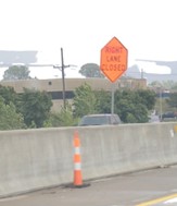 (3)
(3)


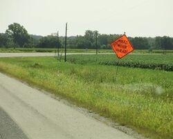 (4)
(4) (5)
(5) (6)
(6) (7)
(7) (8)
(8) (9)
(9)


 (10)
(10)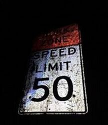 (11)
(11) (12)
(12) (13)
(13)


 (b)
(b)


