751.31 Open Concrete Intermediate Bents
751.31.1 General
751.31.1.1 Material Properties
Concrete
Typically, intermediate bents on footings shall consist of:
- Class B Concrete (Substructure) = 3.0 ksi
- = 10
Typically, intermediate bents on drilled shafts shall consist of:
- Class B-1 Concrete (Substructure) = 4.0 ksi
- = 8
In addition, Class B-1 Concrete (Substructure) may also be used in special cases (See Project Manager). The following equations shall apply to both concrete classes:
| Concrete modulus of elasticity, |
- Where:
- = unit weight of non-reinforced concrete = 0.145 kcf
- = correction factor for source of aggregate = 1.0
| Modulus of rupture: | For minimum reinforcement, | |
| For all other calculations, |
is in units of ksi
Reinforcing Steel
| Minimum yield strength, | 60.0 ksi |
| Steel modulus of elasticity, | 29000 ksi |
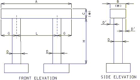
751.31.1.2 Rigid Frame- No Tie or Web Beam
Beam
- A = Length to be determined by the superstructure requirements or the minimum support length required for earthquake criteria, to the
- nearest 1”. Use square ends.
- B = Width to be determined by the minimum of: superstructure requirements, minimum support length required for earthquake criteria, or
- column diameter + 6”. (6” increments) (*)
- C = Depth as required by design. 2’-6” minimum and no less than the column diameter. (3” increments) (*)
- (*) Ratio of beam width to beam depth, B/C, shall be ≤ 1.25
Columns
- D = Column diameter. 2’-6” minimum. Use 3’-0” minimum when the beam depth exceeds 3’-6”. (6” increments)
- D' = Beam width overhang. Controlled by one of the following:
- 1) Beam width controlled by superstructure requirements
- 3” ≤ D' ≤ 6”
- 2) Beam width controlled by minimum support length required for earthquake criteria.
- 3” ≤ D' ≤ 15”
- 2) Beam width controlled by minimum support length required for earthquake criteria.
- L = Spacing as determined by design, with no limit. (1” increments)
- G = Overhang as determined by design, with no limits.
- H = Column height as required by grade and footing elevations. Use construction joint in column when H exceeds 35’-0”.
- NOTE: Try to keep columns and beams the same size where possible for economy of construction.
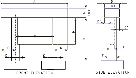
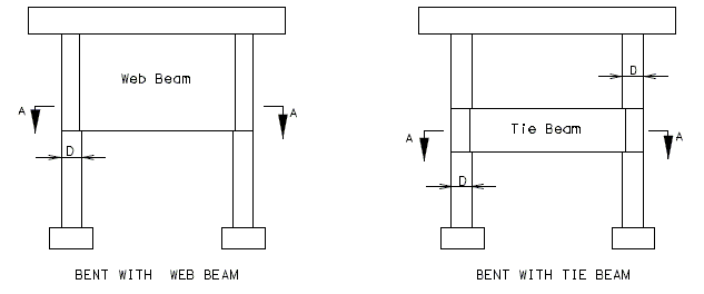
751.31.1.3 Web Beam – Web Supporting Beam
Beam
- A = Length to be determined by the superstructure requirements or the minimum support length required for earthquake criteria, to the
- nearest 1”. Use square ends.
- B = Width to be determined by the minimum of: superstructure requirements, minimum support length required for earthquake criteria, or
- column diameter + 6”. (6” increments) (*)
- C = Depth as required by design. 2’-6” minimum and no less than the column diameter. (3” increments) (*)
- (*) Ratio of beam width to beam depth, B/C, shall be ≤ 1.25
Columns
- D = Column diameter. 3’-0” minimum. (6” increments)
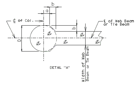
- D' = Beam width overhang. Controlled by one of the following:
- 1) Beam width controlled by superstructure requirements
- 3” ≤ D' ≤ 6”
- 2) Beam width controlled by minimum support length required for earthquake criteria.
- 3” ≤ D' ≤ 15”
- 2) Beam width controlled by minimum support length required for earthquake criteria.
- L = Spacing as determined by design, with 35'-0" maximum. (1” increments)
- G = Overhang as determined by design, with no limits.
- H = Column height as required by grade and footing elevations.
Webs
- T = Web thickness. For a 3’-0” column diameter, use T = column diameter. For column diameters ≥ 3’-6”, use T = 0.5 x (column diameter).
- H' = See bottom elevations of web given on the Design Layout.
- NOTE: Try to keep columns and beams the same size where possible for economy of construction.
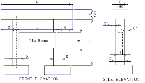
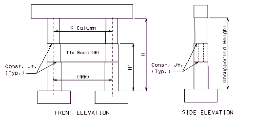
751.31.1.4 Tie Beam
Beam
- A = Length to be determined by the superstructure requirements or the minimum support length required for earthquake criteria, to the
- nearest 1”. Use square ends.
- B = Width to be determined by the minimum of: superstructure requirements, minimum support length required for earthquake criteria, or
- column diameter + 6”. (6” increments) (*)
- C = Depth as required by design. 2’-6” minimum and no less than the column diameter. (3” increments) (*)
- (*) Ratio of beam width to beam depth, B/C, shall be ≤ 1.25
Columns
- D = Column diameter. 3’-0” minimum. (6” increments)
- D' = Beam width overhang. Controlled by one of the following:
- 1) Beam width controlled by superstructure requirements
- 3” ≤ D' ≤ 6”
- 2) Beam width controlled by minimum support length required for earthquake criteria.
- 3” ≤ D' ≤ 15”
- 2) Beam width controlled by minimum support length required for earthquake criteria.
- L = Spacing as determined by design, with 30'-0" maximum. (1” increments)
- G = Overhang as determined by design, with no limits.
- H = Column height as required by grade and footing elevations.
Tie Beam
- T = Tie beam thickness. Minimum T = 0.5 x (column diameter).
- H' = See bottom elevations of tie beam given on the Design Layout. Minimum H' = 2 x T (round to the next foot higher).
- NOTE: Try to keep columns and beams the same size where possible for economy of construction.
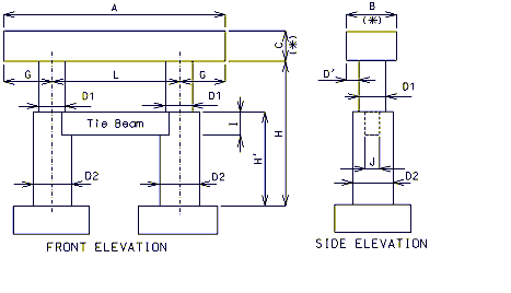
751.31.1.5 Tie Beam with Change in Column Diameter
Beam
- A = Length to be determined by the superstructure requirements or the minimum support length required for earthquake criteria, to the
- nearest 1”. Use square ends.
- B = Width to be determined by the minimum of: superstructure requirements, minimum support length required for earthquake criteria, or
- column diameter + 6”. (6” increments) (*)
- C = Depth as required by design. 2’-6” minimum and no less than the column diameter. (3” increments) (*)
- (*) Ratio of beam width to beam depth, B/C, shall be ≤ 1.25
Columns
- D1 = Column diameter. 3’-0” minimum. (6” increments)
- D2 = Column diameter, Minimum of (D1 + 6”). Check lap of vertical reinforcement required. See Structural Project Manager.
- D' = Beam width overhang. Controlled by one of the following:
- 1) Beam width controlled by superstructure requirements
- 3” ≤ D' ≤ 6”
- 2) Beam width controlled by minimum support length required for earthquake criteria.
- 3” ≤ D' ≤ 15”
- 2) Beam width controlled by minimum support length required for earthquake criteria.
- L = Spacing as determined by design, with a 30’-0” maximum with tie beams and no limit without tie beams. (1” increments)
- G = Overhang as determined by design, with no limits.
- H = Column height as required by grade and footing elevations.
- H' = Approximately 0.5 x H. Top of tie beam should be at the same elevation as the top of the larger diameter columns in order to
- minimize the number of construction joints. Top of tie beam may be located on the Design Layout.
Tie Beam
- I = Depth as required by design. Minimum of 3’-0” (3” increments).
- J = Width as required by design. Minimum of (0.5 x D1).
- NOTE: Try to keep columns and beams the same size where possible for economy of construction.
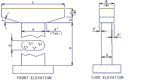
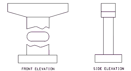
751.31.1.6 Hammer Head Type
Beam
- L = Length to be determined by the superstructure requirements or the minimum support length required for earthquake criteria, to the
- nearest 1”. Use square ends.
- B = Width to be determined by the minimum of: superstructure requirements, minimum support length required for earthquake criteria, or
- column width + 6”. (6” increments) (*)
- C = Depth as required by design. 2’-6” minimum and no less than the column width. (3” increments) (*)
- E = Depth as required by design (see “F”)
- F = Angle as required by design (20° maximum)
- (*) Ratio of beam width to beam depth, B/C, shall be ≤ 1.25
Columns
- A = Length as required by design, approximately L/3. Use round ends for column.
- D = Width as required by design with a minimum of 2’-6”. (6” increments)
- D' = Beam width overhang. Controlled by one of the following:
- 1) Beam width controlled by superstructure requirements
- 3” ≤ D' ≤ 6”
- 1) Beam width controlled by superstructure requirements
- 2) Beam width controlled by minimum support length required for earthquake criteria.
- 3” ≤ D' ≤ 15”
- 2) Beam width controlled by minimum support length required for earthquake criteria.
NOTE: Try to keep columns and beams the same size where possible for economy of construction.
751.31.1.7 Collision Walls
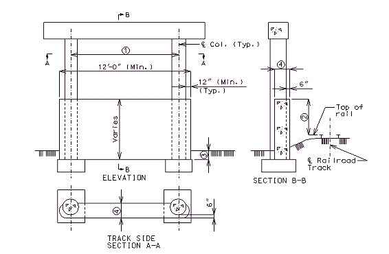
Structure Over Railroad, Track on One Side of Bent
These details are typical for bents with two or more columns.
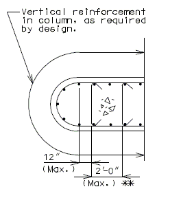
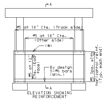
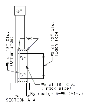
Column faces located within 25’-0” of the centerline of track shall meet standards specified in part 2 or Chapter 8 of the AREA Manual (*) except as modified in this article. Certain railroads have specific requirements that also must be complied with. Check the Preliminary Design Layout data.
| 1= | For column spacing over 25’-0”, see Structural Project Managers. | |||||||||
| 2= | 6’-0” minimum for columns from 12’-0” to 25’-0” clear from the centerline of the track; 12’-0” minimum for columns less than 12’-0” clear from the centerline of the track. | |||||||||
| 3= | In general, the collision wall shall extend to at least 4’-0” below the lowest surrounding grade. For spread footing on rock, the collision wall may extend to less than 4’-0” below the lowest surrounding grade with railroad’s concurrence. Top of footing elevations should correspond with bottom of collision wall. | |||||||||
| 4= |
|
|||||||||
(*) AREA–American Railway Engineering Association
(**) To facilitate construction, match the back face of collision wall to the face of column.
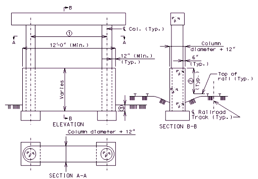
Structure Over Railroad, Track on Both Sides of Bent
These details are typical for bents with two or more columns.
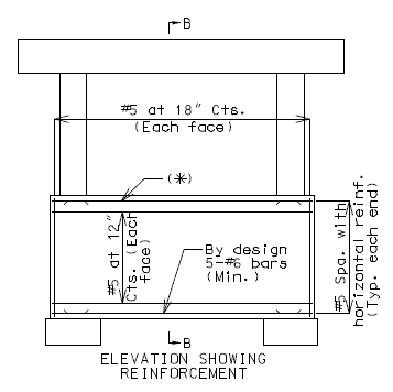
Column faces located within 25’-0” of the centerline of track shall meet standards specified in part 2 or Chapter 8 of the AREA Manual (*) except as modified in this article. Certain railroads have specific requirements that also must be complied with. Check the Preliminary Design Layout data.
| 1= | For column spacing over 25’-0”, see Structural Project Managers. |
| 2= | 6’-0” minimum for columns from 12’-0” to 25’-0” clear from the centerline of the track; 12’-0” minimum for columns less than 12’-0” clear from the centerline of the track. |
| 3= | In general, the collision wall shall extend to at least 4’-0” below the lowest surrounding grade. For spread footing on rock, the collision wall may extend to less than 4’-0” below the lowest surrounding grade with railroad’s concurrence. Top of footing elevations should correspond with bottom of collision wall. |
(*) AREA – American Railway Engineering Association
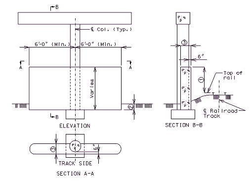
Structure Over Railroad, Track on One Side of Single Column Bent
These details are typical for bents with one column.
Column face located within 25’-0” of the centerline of track shall meet standards specified in part 2 or Chapter 8 of the AREA Manual (*) except as modified in this article. Certain railroads have specific requirements that also must be complied with. Check the Preliminary Design Layout data.
| 1= | 6’-0” minimum for columns from 12’-0” to 25’-0” clear from the centerline of the track; 12’-0” minimum for columns less than 12’-0” clear from the centerline of the track. | ||||||||
| 2= | In general, the collision wall shall extend to at least 4’-0” below the lowest surrounding grade. For spread footing on rock, the collision wall may extend to less than 4’-0” below the lowest surrounding grade with railroad’s concurrence. Top of footing elevations should correspond with bottom of collision wall. | ||||||||
| 3= |
|
(*) AREA – American Railway Engineering Association
(**) To facilitate construction, match the back face of collision wall to the face of column.
751.31.2 Design
751.31.2.1 Limit States and Factors
In general, each component shall satisfy the following equation:
Where:
| = Total factored force effect | |
| = Force effect | |
| = Load modifier | |
| = Load factor | |
| = Resistance factor | |
| = Nominal resistance | |
| = Factored resistance |
Limit States
The following limit states shall be considered for bent design:
- STRENGTH – I
- STRENGTH – III
- STRENGTH – IV
- STRENGTH – V
- SERVICE – I
- EXTREME EVENT– II
See LRFD Table 3.4.1-1 and LRFD 3.4.2 for Loads and Load Factors applied at each given limit state. The minimum load factor for TU should be used in the application of temperature forces. Maximum load factor for TU is used in calculating deformations only.
Service dead loads only are required for the beam cap rupture check. See LRFD DG Sec. 3.71.2.3.
Resistance factors
- STRENGTH limit states, see LRFD 5.5.4.2
- For all other limit states, Ø = 1.00
751.31.2.2 Loads
Dead Loads
- Loads from stringers, girders, etc. shall be applied as concentrated loads applied at the centerline of bearing. Loads from concrete slab spans shall be applied as uniformly distributed loads.
Live Loads
- Loads from stringers, girders, etc. shall be applied as concentrated loads applied at the centerline of bearing. Dynamic load allowance (impact) should be included for the design of the beam, web supporting beam and top of columns. No dynamic load allowance should be included for bottom of column, tie beams or footing design.
Temperature and Shrinkage
- The effect of temperature and shrinkage from the superstructure shall be considered. Columns and footings shall be analyzed for moments normal to the bent due to the horizontal deflection of the top of the bent due to bearings with high friction coefficients.
- The effect of temperature should be applied at the top of the substructure beam.
Buoyancy
- The effect of buoyancy should be analyzed when specified on the Design Layout or by the Structural Project Manager.
Earth Pressure
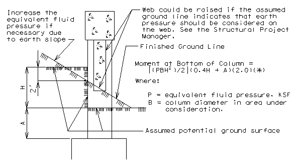
- Moments due to the equivalent fluid pressure of earth on columns and webs shall be analyzed where the ground line at the time of construction or potential changes in the ground line indicate.
- Vertical earth loads on tie beams shall be applied as uniform loads for a column of earth equal to 3 times the width of the beam. The weight of earth for footing design shall be that directly above the footing, excluding that occupied by the column.
- The earth load above seal course shall be considered in computing pile loads. Refer to the Pile Footings portion of the guidelines for design and dimensions of pile.
- For horizontal earth loads the following shall be used:
(*) A factor of 2.0 is applied to the moment to allow for the possibility of the column resisting earth pressure caused by the earth behind the column twice the column width.
Horizontal Earth Load Distributed To Columns
Collision
- Collision walls are to be designed for the unequal horizontal forces from the earth pressure, if the condition exists (See Design Layout). The vertical force on the collision wall is the dead load weight of the wall (*). If a bent has three or more columns, design the steel in the top of the wall for negative moment.
(:*) For footing design, the eccentric dead load moment due to an unsymmetrical collision wall shall be considered.
Seal Course
- The weight of the seal course shall not be considered as contributing to the pile loads, except for unusual cases (See Structural Project Manager).
751.31.2.3 General Design Assumptions
(*) Use only if specified on the Design Layout or as stated by the guidelines in this article.
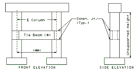
(**) For column spacings greater than 30'-0", tie beams are not to be used, unless the web supports the beam.
Elevations for General Intermediate Bent
General
- The following are general design guidelines for the design of intermediate bents.
- Rigid frame design is to be used for designing Intermediate Bents and Piers.
- The joint between the beam and column, and web or tie beam and column, shall be assumed to be integral for all phases of design and must be analyzed for reinforcement requirements as a “Rigid Frame”.
- The joint between the column and footing is assumed to be “fixed”, unless foundation flexibility needs to be considered as required by the Structural Project Manager.
Beam
- Beams shall be designed for vertical loads, including a dynamic load allowance (impact) and components of horizontal forces.
- The gross concrete section, without contribution from reinforcement, shall not rupture under service dead loads. In addition, longitudinal reinforcement shall be distributed to control cracking at the Service-I limit state.
- Fatigue design should not control the size of reinforcement in the beam. LRFD 5.5.3.2 may be ignored for open concrete intermediate bents.
- The minimum reinforcement shall be such that the factored flexural resistance, Mr, is greater than or equal to the lesser of:
- 1.2 times the cracking strength based on elastic stress distribution and the modulus of rupture, fr, of the concrete as specified in LRFD 5.4.2.6.
- 1.33 times the factored moment required by the applicable strength load combinations.
- Additional reinforcement is required in the sides of the beam. The following table gives adequate steel for both temperature and shrinkage (LRFD 5.10.8), and skin reinforcement (LRFD 5.7.3.4).
Additional side reinforcement required for reinforced concrete beam caps (per face) Beam Height, H Number – Bar Size H ≤ 36” 4 - #6 36” < H < 54” 5 - #6 54” ≤ H ≤ 72” 6 - #6 H > 72” By Design (LRFD 5.7.3.4)
Tie Beam
- Use a tie beam when specified on the Design Layout or by the Structural Project Manager or when the unsupported height exceeds 30 feet, except as noted
- Do not use tie beams on grade separations.
- Do not use tie beams when column spacing exceeds 30 feet. For this situation, use a minimum column diameter of in lieu of a tie beam.
- Additional side reinforcement shall be designed for temperature and shrinkage (LRFD 5.10.8), and skin reinforcement (LRFD 5.7.3.4).
Unsupported Height
- The unsupported height is the distance from the bottom of the beam to the top of the footing. If the distance from the ground line to the top of footing is 10 feet, the unsupported height and the fixed point may be measured from the bottom of the beam to the ground line plus 1/2 the distance from the ground line to the top of the footing.
- For single column intermediate bents, the column shall be considered “fixed” at the top of footing for all conditions.
Columns
- Use round columns for all bridges, unless otherwise specified on the Design Layout.
- Tops of column shall be designed for vertical loads with consideration of dynamic load allowance (impact) and maximum components of horizontal forces. Bottom of columns do not require impact forces to be included.
- The minimum area of reinforcement, As, shall be taken as the greater of:
- Where:
- = gross area of section. (in.²)
Minimum Allowable Bars for Column Reinforcement Design Column Diameter Vertical Reinforcement
(Assuming 1% of Column Gross Area)2’-6” 9 - #8 3’-0” 13 - #8 3’-6” 18 - #8 4’-0” 23 - #8 4’-6” 29 - #8 5’-0” 29 - #9 5’-6” 35 - #9 6’-0” 41 - #9
- The maximum reinforcement shall be limited by the following requirements:
- (Preferred max for seismic design.)
- (Absolute max, LRFD 5.7.4.2)
- Spacing limitations given in this article.
Maximum Allowable Number of Bars for the Given Bar Sizes Column Diameter Maximum Number of Bars #8 #9 #10 #11 2’-6” 18 18 17 15 3’-0” 22 22 21 18 3’-6” 26 26 26 22 4’-0” 30 30 30 25 4’-6” 34 34 34 29 5’-0” 38 38 32 5’-6” 43 42 36 6’-0” 47 46 40
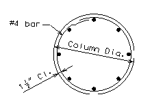
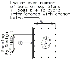
- Above table is applicable for standard dowel bar arrangments, see EPG 751.31.3.2.
- A preliminary economic analysis should be conducted before determining the number of columns and column spacing. For the analysis, assume the rates for Concrete, Class 1 and Class 2 Excavation, and Piles. Omit reinforcing bars in the cost analysis.
Column Spacing
- Columns, with the exception of web supporting beam type bents, shall be spaced, to the nearest 1”, in which balanced positive and negative beam moments are produced. A positive beam moment up to 10% larger than the negative beam moment is acceptable. Strength Limit State Load Combinations shall be used to determine column spacing.
- To estimate centerline-to-centerline spacing for a two column bent, use 72% of the distance from centerline of outside girder to centerline of outside girder. For a three column bent, use 44% of the centerline-to-centerline distance of outside girders.
Footings
- Footings shall be designed for vertical loads and maximum normal and parallel components of the horizontal forces.
Elevations for Intermediate Bent with Web Beam
Web Supporting Beam
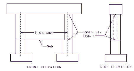
- In analysis, web beams shall be modeled as plate elements. If the ability to model a web beam as a plate element is unavailable, the following may be considered:
Simplified Model
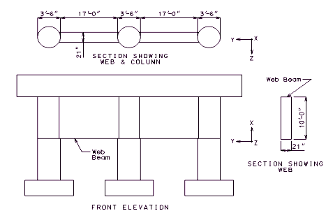
- The web itself is made up of several tie beams (typically 4 tie beams). The moment of inertia of an individual tie beam is equal to the moment of inertia of the web in the bent’s out-of-plane direction divided by the total number of tie beams.
- Any column segment which is connected to the web is treated as a prismatic member with moment of inertia in the bent’s out-of-plane direction equal to the actual column moment of inertia in that direction, and with the moment of inertia in the bent’s in-plane direction equal to the total moment of inertia of web in the bent’s in-plane direction divided by the total number of columns plus the moment of inertia of the column itself. The equivalent column diameter is assumed to be .
Section Views for an Intermediate Bent with Web Beam
In the above example, the moment of inertia of the column in the bent’s in-plane and out-of-plane directions can be calculated as:
| Out-of-plane-> | |
| In-plane-> |
The equivalent column diameter is then assumed to be .
Thus, the column can be treated as a telescoping column and then the moment magnifier or P-δ slenderness effects can be calculated.
Since the web is made up of 4 tie beams, the moment of inertia of the tie beams in the bent’s out-of-plane direction is:
Reinforcement
- Additional side reinforcement shall be designed for temperature and shrinkage (LRFD 5.10.8), and skin reinforcement (LRFD 5.7.3.4).
Column Spacing
- Columns shall be spaced so that the negative moment in the beam over the outside columns requires a minimum beam depth of 3.0 FT. No attempt should be made to use a column spacing that produces equal positive and negative beam moments. The negative moment is to be determined at the face of the column (for round columns, check moment at the face of an equivalent area square column).
(*) Use a tie beam if specified on the Design Layout or if the design calls for one.
(**) For column spacing > 30’, tie beams are not to be used unless the web supports the beam
Elevations for Intermediate Bent with Tie Beam
Change in Column Diameter
- Use rigid frame design.
- If H’ ≤ 0.5H and no tie beam is used, the design may be done assuming the entire column to have the smaller diameter. This will result in a very small error.
Columns
- Use round columns for all bridges, unless otherwise specified on the Design Layout.
- Use two or more columns, as required for the more economical design.
Column Spacing
- Column spacing (to the nearest 1”) should be that which produces balanced positive and negative moments. A positive beam moment up to 10% larger than the negative beam moment is acceptable. Strength Limit State Load Combinations shall be used to determine column spacing.
Reinforcement
- Reinforcement in the beams, column and tie beams for the moments at the joints shall be based on the moment at the face of the column, beam, or tie beam (equivalent square, based on areas, for round columns).
Elevations for Hammer Head Intermediate Bent
Hammer Head Type Intermediate Bent
- Hammer Head type intermediate bents shall be designed according to the applicable provisions listed under the design assumptions for the General intermediate bent guidelines except as follows:
Reinforcement
- Additional side reinforcement shall be designed for temperature and shrinkage (LRFD 5.10.8), and skin reinforcement (LRFD 5.7.3.4).
751.31.2.4 Column Analysis
Refer to this article to check slenderness effects in column and the moment magnifier method of column design. See Structural Project Manager for use of P Delta Analysis.
Transverse Reinforcement
Seismic Zone 1
- Columns shall be analyzed as “Tied Columns”. Unless excessive reinforcement is required, in which case spirals shall be used.
Bi-Axial Bending
Use the resultant of longitudinal and transverse moments.
Slenderness effects in Columns
The slenderness effects shall be considered when:
Where:
= unsupported length of column
= radius of gyration of column cross section
= effective length factor
Effects should be investigated by using either the rigorous P-∆ analysis or the Moment Magnifier Method with consideration of bracing and non-bracing effects. Use of the moment magnifier method is limited to members with Klu/r ≤ 100, or the diameter of a round column must be ≥ Klu/25. A maximum value of 2.5 for moment magnifier is desirable for efficiency of design. Increase column diameter to reduce the magnifier, if necessary.
When a compression member is subjected to bending in both principal directions, the effects of slenderness should be considered in each direction independently. Instead of calculating two moment magnifiers, db and ds, and performing two analyses for M2b and M2s as described in LRFD 4.5.3.2.2b, the following conservative, simplified moment magnification method in which only a moment magnifier due to sidesway, δs, analysis is required:
General Procedure for Bending in a Principal Direction
- Mc = δsM2
- Where:
- Mc = Magnified column moment about the axis under investigation.
- M2 = value of larger column moment about the axis under investigation due to LRFD Load Combinations.
- δs = moment magnification factor for sidesway about the axis under investigation
Where:
| = | summation of individual column factored axial loads for a specific Load Combination (kip) | |
| = | stiffness reduction factor for concrete = 0.75 | |
| = | summation of individual column Euler buckling loads |
Where:
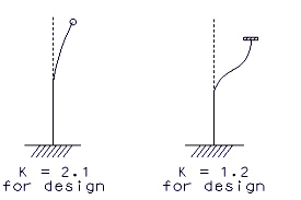
= effective length factor = 1.2 min. (see Figure 3.71.2.4.3)
= unsupported lenth of column (in.)
Where:
= concrete modulus of elasticity as defined in LRFD DG 3.71.1.1 (ksi)
= moment of inertia of gross concrete section about the axis under investigation
= ratio of maximum factored permanent load moments to maximum factored total load moment: always positive
Column Moment Parallel to Bent In-Plane Direction
= top of footing to top of beam cap
Column Moment Normal to Bent In-Plane Direction
= top of footing to bottom of beam cap or tie beam and/or top of tie beam to bottom of beam cap
| Out-of-plane bending Non-integral Bent |
 |
Out-of-plane bending Integral Bent |
| In-plane bending | 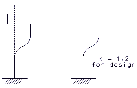 |
Boundary Conditions for columns
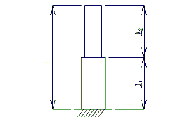
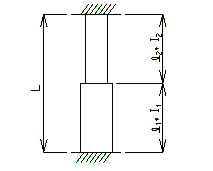
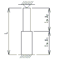
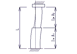
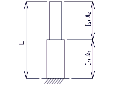
For telescoping columns, the equivalent moment of inertia, I, and equivalent effective length factor, K, can be estimated as follows:
Telescoping Columns
Where:
= length of column segment
= moment of inertia of column segment
= total length of telescoping column
Equivalent Effective Length Factor
Where:
= modulus of elasticity of column
= equivalent moment of inertia of column
= total length of telescoping column
=elastic buckling load solved from the equations given by the following boundary conditions:
Fixed- Fixed Condition
Hinged-Fixed Condition
Where:
and are defined in the previous equations.
Fixed-Fixed with Lateral Movement Condition
Where:
and are defined in the previous equations.
Fixed-Free with Lateral Movement Condition
Where:
and are defined in the previous equations.
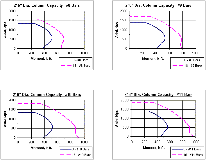
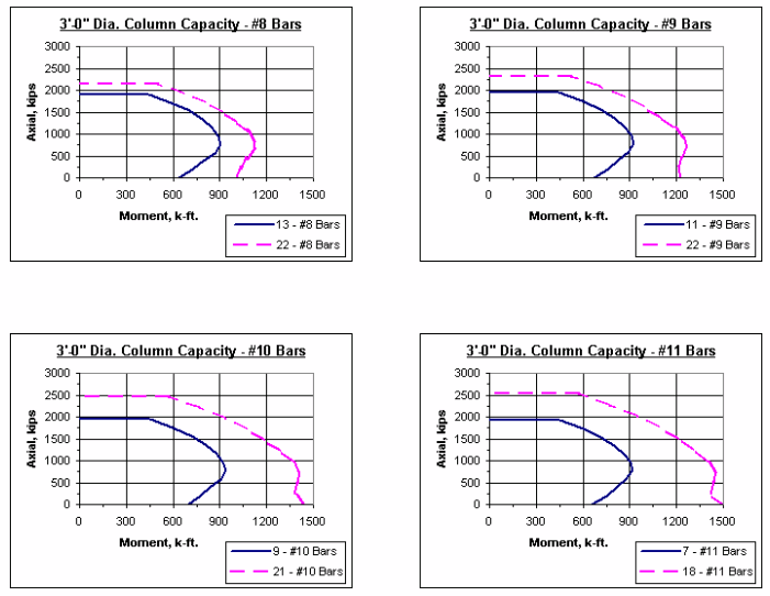
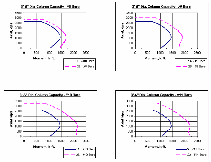
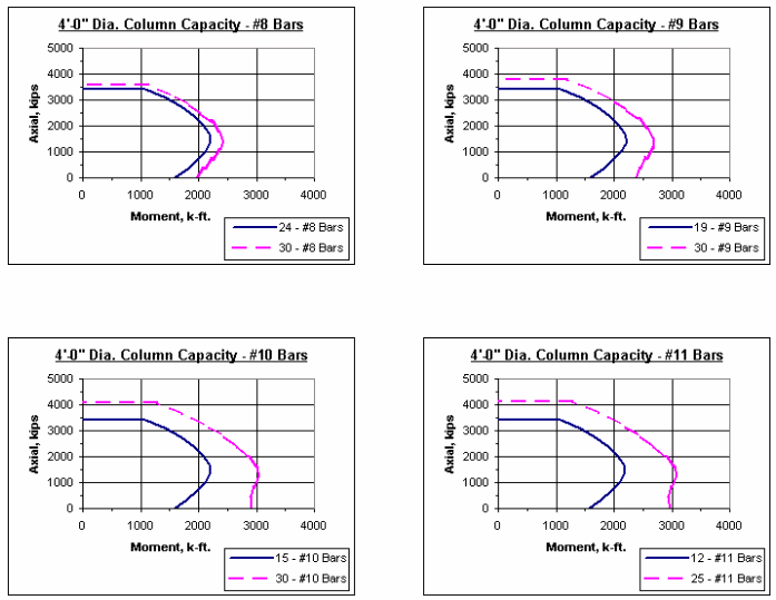
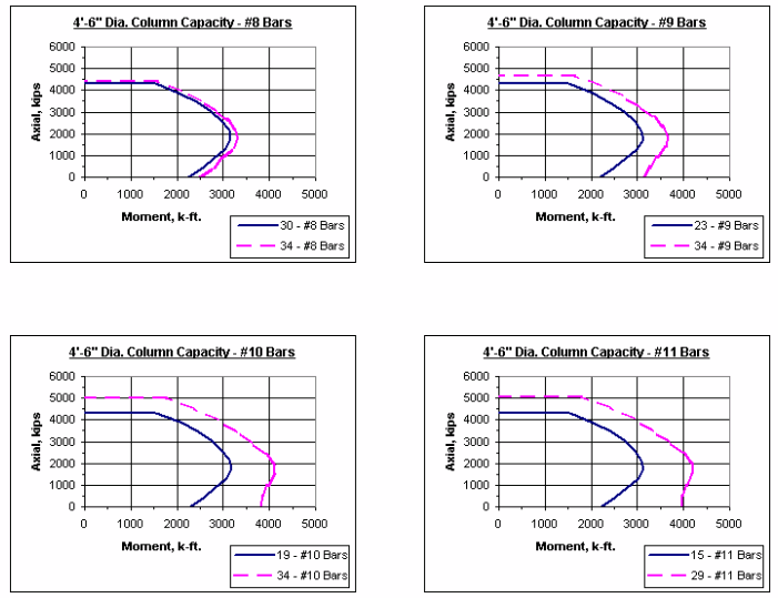
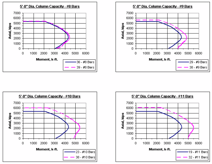
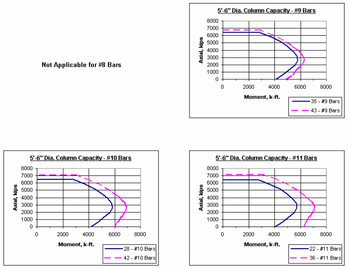
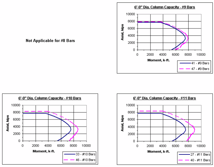
751.31.2.5 Column Charts
Note: The axial-moment interaction curves shown throughout this section represent 1% vertical reinforcement and maximum reinforcement allowed as given in LRFD.
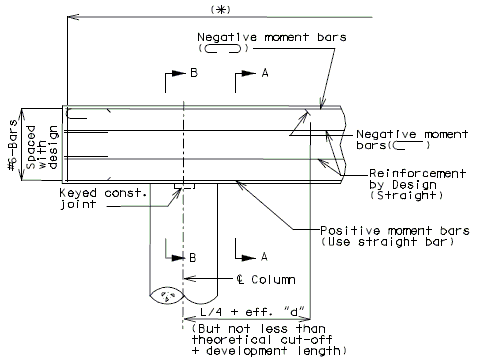
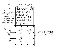
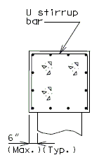
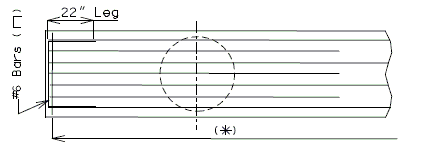
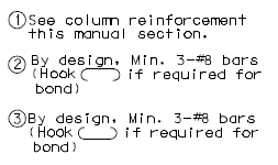
751.31.3 Reinforcement751.31.3.1 Beam Cap
Note:
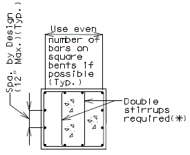
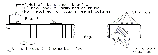
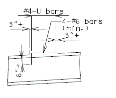
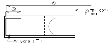
Locate the #4 bars (┌─┐) under the bearings if required. (Not required for prestress double-tee structures). REINFORCEMENT UNDER BEARINGS
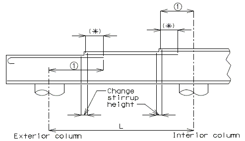
(*) See lap splices. LONGITUDINAL BEAM STEPS 751.31.3.2 Column
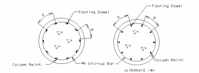
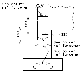
Minimum Allowable Stirrups for Collision (**)
(**) Columns shall be reinforced using stirrup ties, unless excessive reinforcement is required, in which case spirals shall be used.
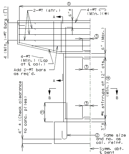
(*) Check development length charts for when to hook column steel. (**) Use splice only when required. 751.31.3.3 Web BeamPART ELEVATION
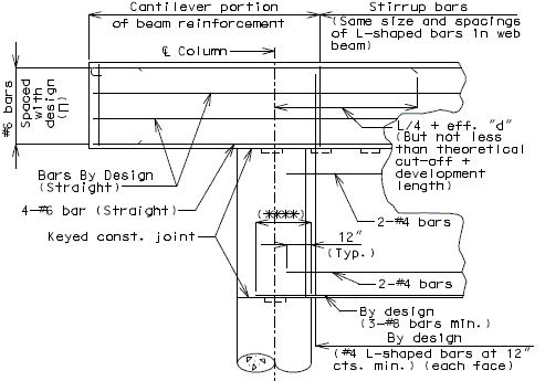
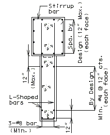
PART SECTION (****) See development length (other than top bars) or standard hooks in tension, Ldh. VARIABLE DIAMETER COLUMNWithout Seismic Detailing
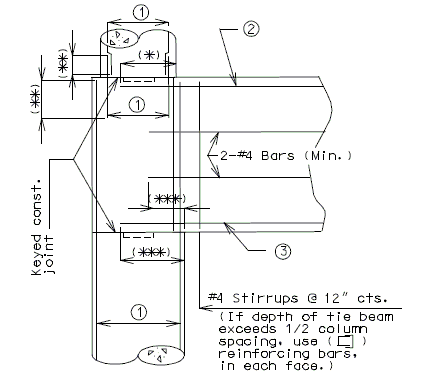
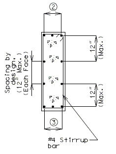
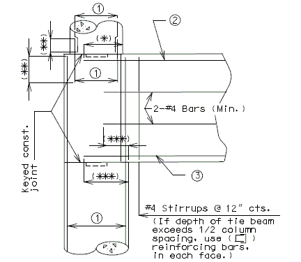
751.31.3.4 Tie Beam
(*) See development length (Top bar) (**) See lap splice (Class C) (***) See development length (Other than top bars) 751.31.3.5 Hammer Head Type
751.31.3.6 Collision Wall
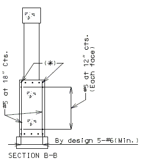
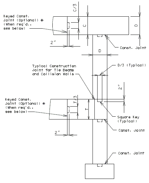
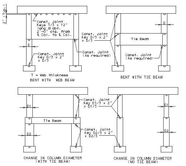
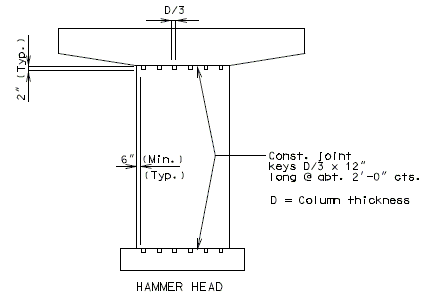
(*) Design and use negative moment reinforcement for bents with three or more columns (5-#6 bars minimum). Reinforcement shown is in addition to column reinforcement. Bent with two columns is shown, single column bent and bent with three or more columns are similar. 751.31.4 Details751.31.4.1 Construction Joints and KeysPART ELEVATION (*) Optional Construction Joints in bearing beam and tie beam: For column height greater than 35'-0" with no tie beam or collision wall, place the construction joint at approximately the mid-point of the column height.
751.31.4.2 Optional Section for Column-Web Beam Joint
Place the following note on plans when using Optional Section A- A. Note: At the contractor’s option, the details shown in Optional Section A-A may be used for Column-Web Beam or Tie Beam at Intermediate Bent No._. No addtional payment will be made for this substitution. (*) Bent with two columns is shown, bents with three or more columns are similar. 751.31.4.3 Substructure Beam OverhangPART ELEVATION (*) Slope 1/8" per foot for drainage. (**) When substructure beam extends beyond the slab as shown, slope end of beam to drain water. |
|||||||||||||||||||||||||||||||||||||||||||||||||||||||||||||||||||||||||||||||||||||||||||||||||||||||||||||||||||||||||||||||||||||||||||||||||||||||
