751.32 Concrete Pile Cap Intermediate Bents
751.32.1 General
751.32.1.1 Material Properties
| Concrete | |||
|---|---|---|---|
| Typically, shall consist of: | |||
| Class B Concrete (Substructure) | = 3.0 ksi | ||
| = 10 | |||
In addition, Class B-1 Concrete (Substructure) may also be used in special cases (See Project Manager). The following equations shall apply to both concrete classes:
Concrete modulus of elasticity:
Where:
| = unit weight of non-reinforced concrete = 0.145 kcf | |
| = correction factor for source of aggregate = 1.0 |
| Modulus of Rupture: | For minimum reinforcement, | |
| For all other calculations, | ||
| is in units of ksi |
Reinforcing Steel
| Minimum yield strength, | = 60.0 ksi | |
| Steel modulus of elasticity, | = 29000 ksi |
751.32.2 Design
751.32.2.1 Limit States and Factors
In general, each component shall satisfy the following equation:
Where:
| = Total factored force effect | |
| = Force effect | |
| = Load modifier | |
| = Load factor | |
| = Resistance factor | |
| = Nominal resistance | |
| = Factored resistance |
Limit States
The following limit states shall be considered for bent design:
- STRENGTH – I
- STRENGTH – III
- STRENGTH – IV
- STRENGTH – V
- SERVICE – I
- FATIGUE
See LRFD Table 3.4.1-1 and LRFD 3.4.2 for Loads and Load Factors applied at each given limit state.
Resistance factors
- STRENGTH limit states, see LRFD 5.5.4.2
- For all other limit states, = 1.00
751.32.3 Details
751.32.3.1 Front Sheet
| Note: | The following are details and dimensions for the plan view of a typical pile cap bent on the front sheet of the bridge plans. Details and dimensions for an encased concrete pile cap bent are similar. |
| Details for unsymmetrical roadways shall require dimensions tying Centerline Lane to Centerline Structure. |
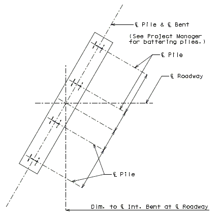
751.32.3.2 Typical Pile Cap Bent
 |
|
| (*) 3" (Typ.) | |
| Part Elevation | Part Section |
|---|---|
| Use 2'-6" minimum or as determined by the superstructure requirements or the minimum support length required for seismic criteria (expansion joint bents only) (3" increments). | |
| = 2'-9" (Min.) for Wide Flange and Double-Tee Girders or, 3'-0" (Min.) for Prestressed Girders and Plate Girders. | |
| Check the clearance of the anchor bolt well to the top of pile. Increase the beam depth if needed. | |
| If the depth at the end of the beam, due to the steps, exceeds 4'-6", the beam bottom should be stepped or sloped. | |
| Use 3/4" drip groove where expansion device is located at bent. Continue to use 1-1/2" clear to reinforcing steel in bottom of beam. 3/4" drip groove shall be formed continuously around all piling at 3" from edge of beam. | |
| Minimum of 3 piles at 10'-0" cts., maximum spacing (1" increments). |
751.32.3.2.1 Sway Bracing
(Use when specified on Design Layout or when required by design.)
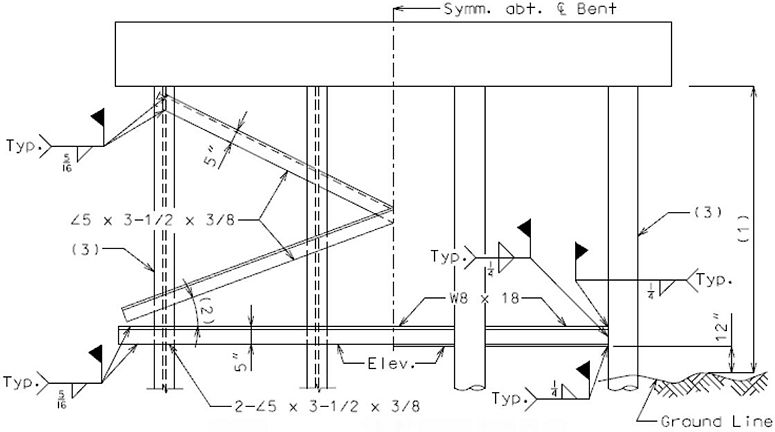
| STEEL BEARING PILE | CAST-IN-PLACE PILE |
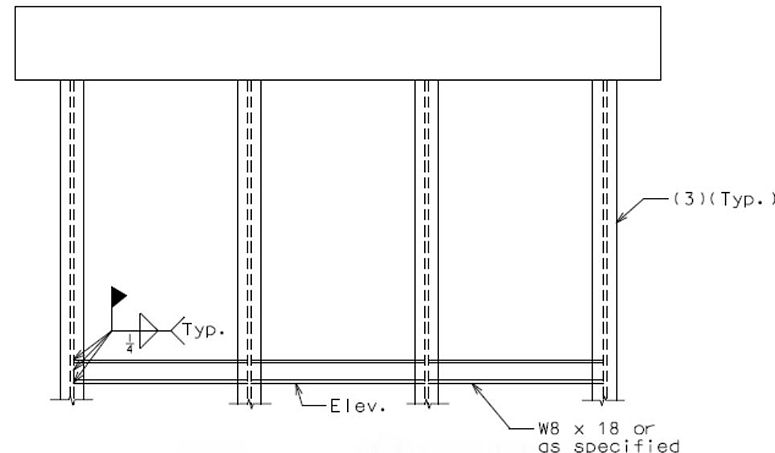
Guidance for use of sway bracing:
| (1) | Omit sway bracing if less than 10'-0" (Cast-In-Place piles only). |
| (2) | When angle slope of bracing becomes less than 15° to the horizontal, omit the diagonal angles and use the horizontal angles only (except on four pile bents, then use alternate shown above). |
| (3) | Piles shall not be battered unless approved by the Structural Project Manager or Structural Liaison Engineer. |
Note: In case of a large number of piles, see the Structural Project Manager.
751.32.3.3 Encased Pile Cap Bent
Consideration shall be given to EPG 751.1.2.19 Substructure Type before using this type of structure.
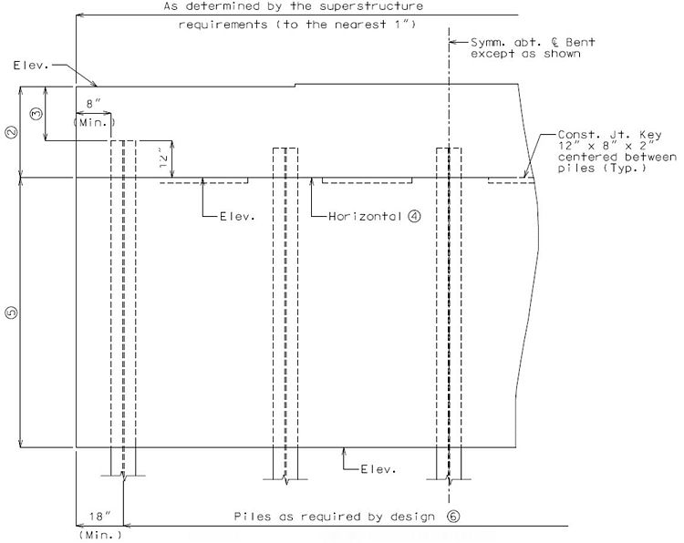 |
| Part Elevation |
|---|
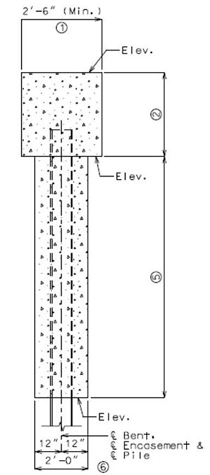 |
| Part Section |
| Use 2'-6" minimum or as determined by the superstructure requirements or the minimum support length required for seismic criteria (expansion joint bents only) (3" increments). | |
| = 2'-9" (Min.) for Wide Flange and Double-Tee Girders or, 3'-0" (Min.) for Prestressed Girders and Plate Girders. | |
| Check the clearance of the anchor bolt well to the top of pile. Increase the beam depth if needed. | |
| If the depth at the end of the beam, due to the steps, exceeds 4'-6", the beam bottom should be stepped or sloped. | |
| Height by design. Embed encasement 2 ft. (min.) below the top of the lowest finished groundline elevation, unless a greater embedment is required for bridge design. | |
| Minimum of 3 piles at 10'-0" cts., maximum spacing (1" increments). |
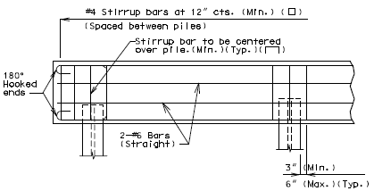
751.32.4 Reinforcement
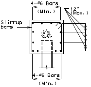
751.32.4.1 Typical Pile Cap Bent
|
|
| Part Elevation | Section Thru Beam |
|---|---|

|
|
| Part Plan | |
|
|
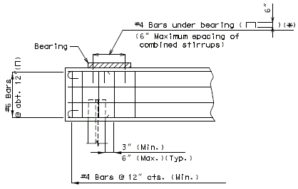
| * #4 Bars ( | |
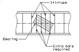
| Reinforcement Under Bearings | |
|---|---|

| |
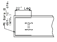
| Transverse Beam Steps - Over 3" or Steps Accumulating Over 3" | |
| |
| Part Plan | |
|---|---|
| |
| Over 3" thru 12" | Over 12" |
| Longitudinal Beam Steps | |
751.32.4.2 Encased Pile Cap Bent
Supplemental details for encased pile cap bents are provided.
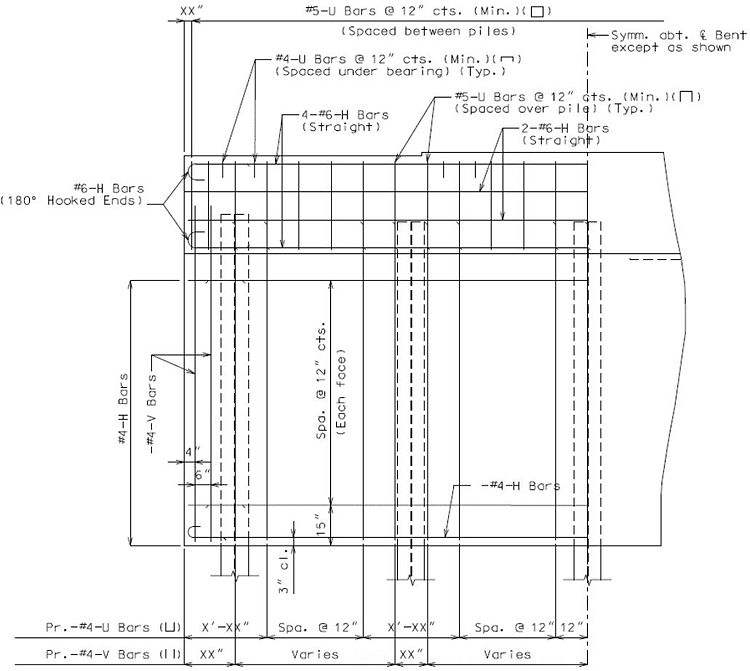 |
| Part Elevation |
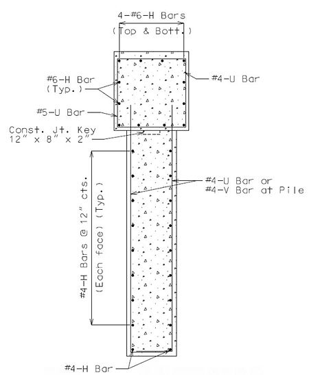 |
| Part Section |
 |
| Part Plan |