Uncategorized files
Jump to navigation
Jump to search
Showing below up to 50 results in range #11,501 to #11,550.
-
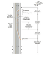
 Fig 643.1.6-06 2026.jpg 2,248 × 511; 150 KB
-
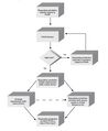
 Fig 751.9.1.png 1,449 × 929; 506 KB
-
 Figure 106.7.20.3.gif 744 × 500; 25 KB
-
 Figure 135.6.jpg 833 × 1,083; 105 KB
-
 Figure 136.3.20, 07 2022.docx ; 12 KB
-
-
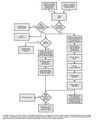 Figure 1B-2. Process for Incorporating New Traffic Control Devices into the MUTCD.jpg 2,230 × 2,791; 562 KB
-
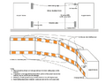 Figure 616.11.2 Pedestrian Channelizing Device.png 628 × 494; 144 KB
-
-
-
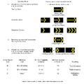 Figure 616.12.6 Advance Warning Arrow Board Specifications.png 2,138 × 2,122; 138 KB
-
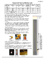 Figure 616.12.7 Sequential Flashing Warning Light.png 2,400 × 3,106; 1.49 MB
-
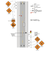
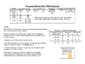 Figure 616.13.6.1 Temporary Rumble Strip Placement.png 2,400 × 1,800; 485 KB
-
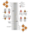
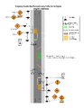 Figure 616.13.6.2 Temporary Rumble Strip Placement using Traffic Control Signals.png 2,400 × 3,106; 427 KB
-
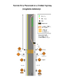 Figure 616.13.6.3 Rumble Strip Placement on a Divided Highway.png 2,400 × 3,106; 361 KB
-
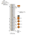 Figure 616.14.19 Late Merge.png 996 × 1,213; 266 KB
-
 Figure 616.2.1 Road Closed Beyond.pdf 1,275 × 1,650; 7 KB
-
 Figure 616.2.1a Road Closed Beyond.pdf 1,275 × 1,650; 7 KB
-
 Figure 616.2.1a Road Closed Beyond Detour.pdf 1,275 × 1,650; 7 KB
-
-
 Figure 616.2.5 Road Closed Beyond.pdf 1,275 × 1,650; 7 KB
-
 Figure 616.2.6 One-Lane Two-Way Operation.pdf 1,275 × 1,650; 7 KB
-
 Figure 616.2.6 One-Lane Two-Way Operation a.pdf 1,275 × 1,650; 7 KB
-
 Figure 616.2.6 One-Lane Two-Way Operation temp.pdf 1,275 × 1,650; 7 KB
-
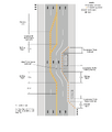 Figure 616.2.6 Types of Tapers and Buffer Spaces.png 1,275 × 1,504; 297 KB
-
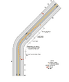 Figure 616.2.8 Example of a One-Lane, Two-Way Traffic Taper.png 608 × 726; 130 KB
-
 Figure 616.4.1.jpg 512 × 892; 67 KB
-
 Figure 616.4.1 Road Closed Beyond.pdf 1,275 × 1,650; 7 KB
-
 Figure 616.4.1a Road Closed Beyond.pdf 1,275 × 1,650; 7 KB
-
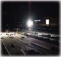 Figure 616.4.2.jpg 251 × 236; 19 KB
-
 Figure 616.4.2 One-Lane Two-Way Operation.pdf 1,275 × 1,650; 7 KB
-
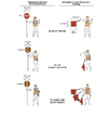 Figure 616.4.2 Use of Hand-Signaling Devices by Flaggers.png 612 × 730; 118 KB
-
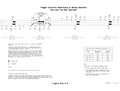 Figure 616.4.2a One-Lane Two-Way Operation.pdf 1,558 × 1,183, 5 pages; 236 KB
-
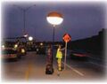 Figure 616.4.3.jpg 321 × 253; 18 KB
-
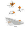 Figure 616.6.2.3 Methods of Mounting Signs Other Than on Posts.png 644 × 710; 137 KB
-
 Figure 616.6.87.1 Rumble Strip Placement-January2023.jpg 1,700 × 2,200; 436 KB
-
 Figure 616.6.87.1 Rumble Strip Placement-January2023.pdf 0 × 0; 748 KB
-
 Figure 616.7.1.gif 545 × 344; 6 KB
-
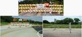 Figure 616.7.2.jpg 790 × 357; 60 KB
-
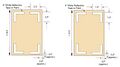 Figure 616.8.25 Examples of Markings on Steel Plates.jpg 858 × 481; 41 KB
-
-
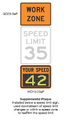 Figure 616.8.40 Vehicle Speed Feedback Plaque.png 405 × 728; 158 KB
-
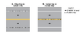 Figure 620.10.1 Examples of Longitudinal Rumble Strip Markings.png 1,500 × 623; 17 KB
-
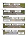 Figure 620.11.1.jpg 920 × 1,191; 194 KB
-
 Figure 620.11 Hand Held Retroreflectometer Readings.gif 649 × 523; 5 KB
-
 Figure 620.14.2.png 612 × 430; 45 KB
-
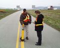 Figure 620.16 Retroreflectivity Reading.jpg 1,280 × 1,024; 264 KB
-
 Figure 620.2.1.1 Yellow Center Lines for Two-Lane, Two-Way Applications.png 1,500 × 697; 36 KB
-
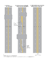 Figure 620.2.1.2 Yellow Center Lines for Four-or-More Lane, Two-Way Applications.png 2,550 × 3,300; 139 KB
-
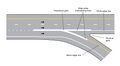 Figure 620.2.10 Example of Channelizing Line Markings at Ramp Gores.jpg 2,182 × 1,192; 117 KB


.png)
.png)


