Gallery of new files
Jump to navigation
Jump to search
This special page shows the last uploaded files.
-
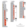 Figure 620.7.7 Examples of Red-Colored Pavement Applications.png Hoskir
13:58, 6 January 2026
1,485 × 1,500; 96 KB
-
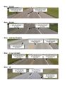
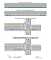 Figure 620.7.6 Examples of Green-Colored Pavement Applications.png Hoskir
13:58, 6 January 2026
2,550 × 2,979; 161 KB
-
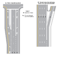 Figure 620.7.5 Examples of White-Colored Pavement Applications.png Hoskir
13:58, 6 January 2026
1,557 × 1,500; 68 KB
-
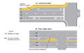 Figure 620.7.4 Examples of Yellow-Colored Pavement Applications.png Hoskir
13:58, 6 January 2026
1,500 × 950; 52 KB
-
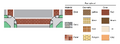 Figure 620.7.3 Aesthetic Treatments for Transverse Crosswalks.png Hoskir
13:58, 6 January 2026
1,500 × 555; 41 KB
-
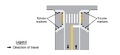 Figure 620.9.7 Examples of Sidewalk Extensions Designated by Pavement Markings.png Hoskir
13:01, 6 January 2026
1,500 × 690; 45 KB
-
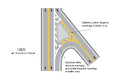 Figure 620.9.5.3 Examples of Optional Chevron and Diagonal Pavement Markings at a Raised Island.png Hoskir
13:01, 6 January 2026
1,828 × 1,216; 150 KB
-
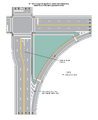 Figure 620.9.5.2 Examples of Pavement Markings for Raised Islands (Sheet 2 of 2).png Hoskir
13:01, 6 January 2026
1,500 × 1,843; 141 KB
-
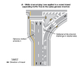 Figure 620.9.5.1 Examples of Pavement Markings for Raised Islands (Sheet 1 of 2).png Hoskir
13:01, 6 January 2026
1,500 × 1,303; 103 KB
-
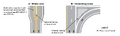 Figure 620.9.4 Examples of Curb Markings for Raised Islands.png Hoskir
13:01, 6 January 2026
1,500 × 448; 54 KB
-
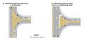 Figure 620.9.3 Examples of Island Designated by Pavement Markings.png Hoskir
13:01, 6 January 2026
1,500 × 731; 57 KB
-
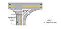 Figure 620.9.2 Example of Markings for an Approach-End Treatment to an Island.png Hoskir
13:01, 6 January 2026
1,500 × 712; 37 KB
-
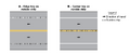 Figure 620.10.1 Examples of Longitudinal Rumble Strip Markings.png Hoskir
12:52, 6 January 2026
1,500 × 623; 17 KB
-
-
-
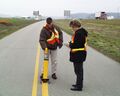
 Figure 620.11 Hand Held Retroreflectometer Readings.gif Hoskir
10:12, 6 January 2026
649 × 523; 5 KB
-
-
-
-
-
-
-
-
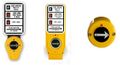
 Figure 902.18.2 Typical Intersection Control Beacon Configuration.png Hoskir
11:38, 5 January 2026
1,500 × 979; 100 KB
-
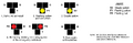 Figure 902.14.2 Sequence for an Emergency-Vehicle Hybrid Beacon.png Hoskir
11:38, 5 January 2026
2,374 × 768; 257 KB
-
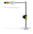 Figure 902.13.2 Typical Emergency Vehicle Signal Layouts.png Hoskir
11:38, 5 January 2026
2,550 × 2,638; 109 KB
-
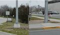
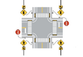 Figure 902.12.2 Example of RRFBs at Uncontrolled, Marked Crosswalks at an Intersection.png Hoskir
11:38, 5 January 2026
1,893 × 1,301; 385 KB
-
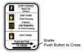 Figure 902.11.1 Example of Braille Sign Legend for Accessible Pedestrian Signals.jpg Hoskir
11:38, 5 January 2026
595 × 381; 35 KB
-
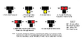 Figure 902.10.2 Sequence for a Pedestrian Hybrid Beacon.png Hoskir
11:38, 5 January 2026
2,359 × 1,114; 408 KB
-
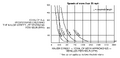 Figure 902.10.1.2 Guidelines for the Installation of Pedestrian Hybrid Beacons on High-Speed Roadways.png Hoskir
11:38, 5 January 2026
2,371 × 1,155; 314 KB
-
-
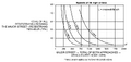 Figure 902.10.1.1 Guidelines for the Installation of Pedestrian Hybrid Beacons on Low-Speed Roadways.png Hoskir
11:38, 5 January 2026
2,358 × 1,117; 329 KB
-
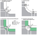 Figure 902.9.5.2 Typical Push Button Locations.png Hoskir
11:38, 5 January 2026
2,146 × 2,043; 342 KB
-
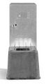
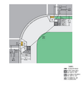 Figure 902.9.5.1 Preferred Push Button Location Area.png Hoskir
11:38, 5 January 2026
2,125 × 2,207; 498 KB
-
 Figure 902.9.2 Typical Pedestrian Signal Indications.jpg Hoskir
11:38, 5 January 2026
1,224 × 353; 81 KB
-
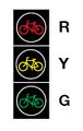 Figure 902.8.6 Typical Arrangements of Bicycle Signal Faces.jpg Hoskir
11:38, 5 January 2026
204 × 321; 14 KB
-
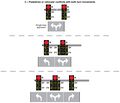 Figure 902.6.16.3 Signal Indications for Approaches with a Combined Left-Turn Right-Turn Lane and No Through Movement (Sheet 3 of 3).jpg Hoskir
11:38, 5 January 2026
2,128 × 1,828; 565 KB
-
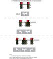 Figure 902.6.16.2 Signal Indications for Approaches with a Combined Left-Turn Right-Turn Lane and No Through Movement (Sheet 2 of 3).jpg Hoskir
11:38, 5 January 2026
2,128 × 2,376; 701 KB
-
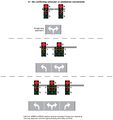 Figure 902.6.16.1 Signal Indications for Approaches with a Combined Left-Turn Right-Turn Lane and No Through Movement (Sheet 1 of 3).jpg Hoskir
11:38, 5 January 2026
2,128 × 2,257; 650 KB
-
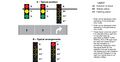 Figure 902.6.15 Typical Position and Arrangements of Separate Signal Faces with Flashing Yellow Arrow for Protected Permissive Mode and Variable Mode Right Turns.jpg Hoskir
11:38, 5 January 2026
2,168 × 1,129; 547 KB
-
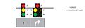 Figure 902.6.14 Typical Position of Shared Signal Faces for Protected Permissive Mode Right Turns.jpg Hoskir
11:38, 5 January 2026
1,737 × 573; 152 KB
-
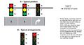 Figure 902.6.13 Typical Position and Arrangements of Separate Signal Faces for Protected Only Mode Right Turns.jpg Hoskir
11:38, 5 January 2026
1,831 × 990; 415 KB
-
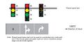 Figure 902.6.12 Typical Position of Shared Signal Faces for Protected Only Mode Right Turns.jpg Hoskir
11:38, 5 January 2026
1,743 × 869; 281 KB
-
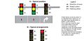 Figure 902.6.11 Typical Position and Arrangements of Separate Signal Faces with Flashing Yellow Arrow for Permissive Only Mode Right Turns.jpg Hoskir
11:38, 5 January 2026
1,987 × 982; 445 KB
-
 Figure 902.6.10 Typical Position of Shared Signal Faces for Permissive Only Mode Right Turns.jpg Hoskir
11:38, 5 January 2026
1,735 × 577; 142 KB
-
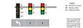 Figure 902.6.8 Typical Position of Separate Signal Faces with Flashing Yellow Arrow for Protected Permissive Mode and Variable Mode Left Turns.jpg Hoskir
11:38, 5 January 2026
1,956 × 673; 264 KB
-
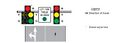 Figure 902.6.7 Typical Position of Shared Signal Faces for Protected Permissive Mode Left Turns.jpg Hoskir
11:38, 5 January 2026
1,735 × 617; 189 KB
-
 Figure 902.6.6 Typical Position of Separate Signal Faces for Protected Only Mode Left Turns.jpg Hoskir
11:38, 5 January 2026
1,752 × 577; 171 KB
-
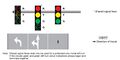 Figure 902.6.5 Typical Position of Shared Signal Faces for Protected Only Mode Left Turns.jpg Hoskir
11:38, 5 January 2026
1,729 × 864; 283 KB
-
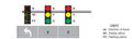 Figure 902.6.4 Typical Position of Separate Signal Faces with Flashing Yellow Arrow for Permissive Only Mode Left Turns.jpg Hoskir
11:38, 5 January 2026
1,888 × 567; 190 KB


.png)
.png)


.jpg)
.jpg)
.jpg)


