Uncategorized files
Jump to navigation
Jump to search
Showing below up to 50 results in range #5,901 to #5,950.
-
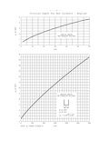
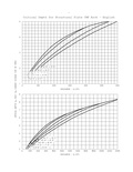
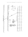
 750.1 Pipe Flow Chart 84 inch.pdf 1,275 × 1,650; 103 KB
-
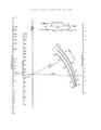
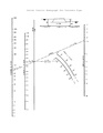
 750.1 Rectangular Channel 10 ft.pdf 1,275 × 1,650; 18 KB
-
 750.1 Rectangular Channel 12 ft.pdf 1,275 × 1,650; 18 KB
-
 750.1 Rectangular Channel 14 ft.pdf 1,275 × 1,650; 17 KB
-
 750.1 Rectangular Channel 4 ft.pdf 1,275 × 1,650; 18 KB
-
 750.1 Rectangular Channel 5 ft.pdf 1,275 × 1,650; 18 KB
-
 750.1 Rectangular Channel 6 ft.pdf 1,275 × 1,650; 19 KB
-
 750.1 Rectangular Channel 7 ft.pdf 1,275 × 1,650; 18 KB
-
 750.1 Rectangular Channel 8 ft.pdf 1,275 × 1,650; 18 KB
-
 750.1 Rectangular Channel 9 ft.pdf 1,275 × 1,650; 18 KB
-
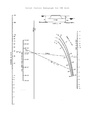
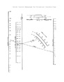
 750.1 Trapezoidal Channel 10 ft.pdf 1,275 × 1,650; 16 KB
-
 750.1 Trapezoidal Channel 12 ft.pdf 1,275 × 1,650; 16 KB
-
 750.1 Trapezoidal Channel 6 ft.pdf 1,275 × 1,650; 16 KB
-
 750.1 Trapezoidal Channel 7 ft.pdf 1,275 × 1,650; 16 KB
-
 750.1 Trapezoidal Channel 8 ft.pdf 1,275 × 1,650; 16 KB
-
 750.1 Trapezoidal Channel 8 ft 6to1 2to1.pdf 1,275 × 1,650; 16 KB
-
 750.1 Trapezoidal Channel 8 ft 6to1 3to1.pdf 1,275 × 1,650; 15 KB
-
 750.1 Trapezoidal Channel 9 ft.pdf 1,275 × 1,650; 16 KB
-
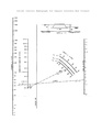
 750.1 Triangular Channel 3to1 2to1.pdf 1,275 × 1,650; 15 KB
-
 750.1 Triangular Channel 4to1 2to1.pdf 1,275 × 1,650; 15 KB
-
 750.1 Triangular Channel 4to1 3to1.pdf 1,275 × 1,650; 15 KB
-
 750.1 Triangular Channel 4to1 4to1.pdf 1,275 × 1,650; 15 KB
-
 750.1 Triangular Channel 6to1 2to1.pdf 1,275 × 1,650; 15 KB
-
 750.1 Triangular Channel 6to1 3to1.pdf 1,275 × 1,650; 15 KB
-
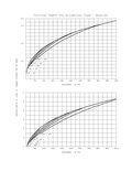
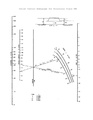
 750.2 Critical Depth for Box Culverts.pdf 1,477 × 1,256, 2 pages; 34 KB
-
 750.2 Critical Depth for CMP Arch.pdf 1,450 × 1,272, 2 pages; 43 KB
-
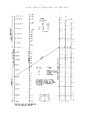
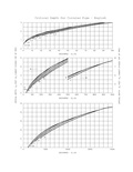 750.2 Critical Depth for Circular Pipe.pdf 1,470 × 1,260, 2 pages; 54 KB
-
 750.2 Critical Depth for Elliptical Concrete Pipe.pdf 1,487 × 1,262, 2 pages; 45 KB
-
 750.2 Critical Depth for Structural Plate CMP Arch.pdf 1,450 × 1,272, 2 pages; 45 KB
-
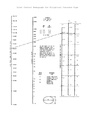
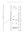 750.2 Inlet Control Nomograph for Box Culverts.pdf 1,275 × 1,650; 29 KB
-
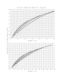
 750.2 Inlet Control Nomograph for CMP.pdf 1,275 × 1,650; 34 KB
-
 750.2 Inlet Control Nomograph for CMP Arch.pdf 1,275 × 1,650; 37 KB
-
 750.2 Inlet Control Nomograph for Concrete Pipe.pdf 1,275 × 1,650; 31 KB
-
 750.2 Inlet Control Nomograph for Elliptical Concrete Pipe.pdf 1,275 × 1,650; 33 KB
-
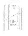
 750.2 Outlet Control Nomograph for CMP.pdf 1,275 × 1,650; 30 KB
-
 750.2 Outlet Control Nomograph for CMP Arch.pdf 1,275 × 1,650; 30 KB
-
 750.2 Outlet Control Nomograph for Concrete Pipe.pdf 1,275 × 1,650; 29 KB
-
 750.2 Outlet Control Nomograph for Elliptical Concrete Pipe.pdf 1,275 × 1,650; 30 KB
-
 750.2 Outlet Control Nomograph for Square Concrete Box Culvert.pdf 1,275 × 1,650; 30 KB
-
 750.2 Outlet Control Nomograph for Structural Plate CMP.pdf 1,275 × 1,650; 31 KB
-
 750.2 Outlet Control Nomograph for Structural Plate CMP Arch.pdf 1,275 × 1,650; 31 KB
-
 750.3.1.1.1.jpg 792 × 697; 135 KB
-
 750.3.1.8.1.jpg 857 × 815; 47 KB
-
 750.3 Abutment and Pier Location Limits.gif 676 × 272; 5 KB
-
 750.3 Bottom of Footing Placement.gif 744 × 500; 25 KB
-
 750.3 Typical Excavation for a Flood Channel.gif 701 × 221; 7 KB
-
 750.4.4.6.jpg 852 × 225; 23 KB
-
 750.6.5.jpg 1,057 × 1,287; 422 KB
-
 750.6.jpg 647 × 776; 152 KB
-
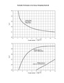 750.6 Hydraulic Performance of an Energy Dissipating Headwall.pdf 1,275 × 1,650; 23 KB


