Uncategorized files
Jump to navigation
Jump to search
Showing below up to 50 results in range #6,121 to #6,170.
View (previous 50 | next 50) (20 | 50 | 100 | 250 | 500)
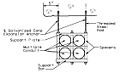
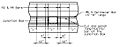
 751.10.4 Multiple Conduits in Safety Barrier 2017.jpg 786 × 459; 42 KB
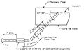
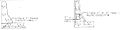
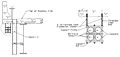
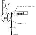 751.10.4 Part Section Suspended Conduit.jpg 947 × 908; 66 KB
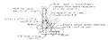
 751.10.4 Part Section Suspended Conduit Detail A.jpg 1,116 × 683; 77 KB
 751.10.4 Safety Barrier Curb.jpg 1,293 × 237; 9 KB
 751.10.4 Safety Barrier Curb 2017.jpg 1,897 × 660; 97 KB
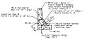
 751.10.4 Safety Barrier Curb Detail A.jpg 1,102 × 864; 72 KB
 751.10.4 Safety Barrier Curb Detail B.jpg 1,444 × 895; 92 KB
 751.10.4 Safety Barrier Curb over Slab.jpg 500 × 160; 21 KB
 751.10.4 Safety Barrier Curb over Slab 2017.jpg 1,086 × 421; 57 KB
 751.10.4 Sections of Single Conduit.jpg 687 × 173; 20 KB
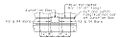
 751.10.4 Section through Safety Barrier Curb.jpg 614 × 232; 31 KB
 751.10.4 Section through Safety Barrier Curb 2017.jpg 1,115 × 533; 75 KB
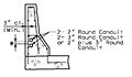
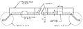
 751.10.4 Section through Safety Barrier Curb Multiple Conduits.jpg 609 × 239; 32 KB
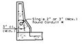 751.10.4 Single Conduit in safety barrier curb.jpg 825 × 448; 36 KB
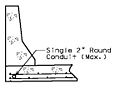 751.10.4 Single Conduit in slab.jpg 573 × 426; 29 KB
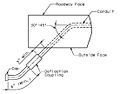
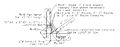
 751.10.4 Suspended Conduit.jpg 809 × 382; 40 KB
 751.10 bottom of slab elevation table continuous spans.gif 744 × 500; 25 KB
 751.10 bottom of slab elevation table simple spans.gif 744 × 500; 25 KB
 751.10 design case 1 sbc loading.gif 192 × 126; 2 KB
 751.10 design case 1 slab design loading.gif 196 × 80; 2 KB
 751.10 design case 2.gif 181 × 140; 2 KB
 751.10 design case 3.gif 167 × 122; 2 KB
 751.10 detail a (precast panels).gif 744 × 500; 25 KB
 751.10 double drip bevel.gif 744 × 500; 25 KB
 751.10 elevation of drain bulb-tee 3ft8in+ cantilever.gif 744 × 500; 25 KB
 751.10 elevation of drain bulb-tee 3ft8in- cantilever.gif 744 × 500; 25 KB
 751.10 elevation of drain cont conc structure.gif 744 × 500; 25 KB
 751.10 elevation of drain double-tee.gif 403 × 263; 7 KB
 751.10 elevation of drain psi and steel structure.gif 744 × 500; 25 KB
 751.10 Epoxy coated reinforcement in backwall.gif 744 × 500; 25 KB
 751.10 Example Slab Cross Section for Cracking Check.gif 373 × 202; 5 KB
 751.10 grade separation with paved slope protection.gif 588 × 252; 9 KB
 751.10 HL93 24-0 ROADWAY - 4 GIRDER.gif 551 × 334; 13 KB
 751.10 HL93 26-0 ROADWAY - 4 GIRDER.gif 548 × 330; 13 KB
 751.10 HL93 28-0 ROADWAY - 4 GIRDER.gif 546 × 330; 13 KB
 751.10 HL93 30-0 ROADWAY - 4 GIRDER.gif 551 × 330; 13 KB
 751.10 HL93 32-0 ROADWAY - 4 GIRDER.gif 552 × 328; 13 KB
 751.10 HL93 36-0 ROADWAY - 5 GIRDER.gif 593 × 324; 13 KB
 751.10 HL93 38-0 ROADWAY - 5 GIRDER.gif 592 × 325; 13 KB
 751.10 HL93 40-0 ROADWAY - 5 GIRDER.gif 598 × 324; 13 KB
 751.10 HL93 44-0 ROADWAY - 5 GIRDER.gif 592 × 325; 13 KB
 751.10 longintudinal joint for prestressed girder.gif 568 × 149; 4 KB
 751.10 longintudinal joint for voided slab.gif 558 × 162; 5 KB
 751.10 longintudinal joint for wide flange or plate girder.gif 568 × 155; 4 KB
 751.10 Method of computing b (Slab on Tangent Alignment).gif 567 × 316; 9 KB
 751.10 Negative Moment Steel Diagram for Steel Structures.gif 510 × 165; 3 KB
 751.10 panels - section a-a.gif 744 × 500; 25 KB
 751.10 panels - section a-a steel structure.gif 744 × 500; 25 KB
 751.10 panels - section b-b steel structure.gif 744 × 500; 25 KB
 751.10 panels - section thru cantilever.gif 744 × 500; 25 KB


.gif)


.gif)


