Uncategorized files
Jump to navigation
Jump to search
Showing below up to 50 results in range #6,971 to #7,020.
View (previous 50 | next 50) (20 | 50 | 100 | 250 | 500)
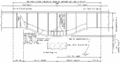
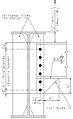 751.14 End Diaphragm Connections.jpg 576 × 942; 59 KB
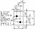
 751.14 End Diaphragm Connections for W21 thru W24 Beams.gif 337 × 281; 6 KB
 751.14 End Diaphragm Connections for W27 thru W40 Beams.gif 744 × 500; 25 KB
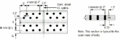 751.14 flange bolt patterns-staggered bolt pattern.gif 532 × 176; 8 KB
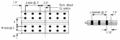 751.14 flange bolt patterns-uniform bolt pattern.gif 522 × 175; 6 KB
 751.14 flange connection angles-plan.gif 203 × 171; 4 KB
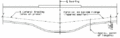
 751.14 flange width transition at splice.gif 571 × 239; 5 KB
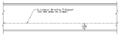
 751.14 girder elevation variation sketch-table.gif 552 × 131; 3 KB
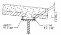
 751.14 girder haunch-cast-in-place section crowned roadway.gif 256 × 191; 4 KB
 751.14 girder haunch-prestressed panel section.gif 264 × 151; 4 KB
 751.14 Intermediate Diaphragm Connection Plate Optional.jpg 490 × 417; 26 KB
 751.14 Intermediate Diaphragm Connection Plate Preferred.jpg 490 × 433; 27 KB
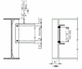
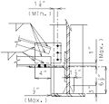
 751.14 int web stiffener.jpg 788 × 723; 41 KB
 751.14 int web stiffener (one side only) variable flange width.gif 744 × 500; 25 KB
 751.14 lateral bracing-constant-variable depth girders.gif 558 × 147; 4 KB
 751.14 lateral bracing-constant depth girders.gif 550 × 166; 3 KB
 751.14 lateral bracing-tapered-variable depth girders.gif 531 × 166; 5 KB
 751.14 lateral bracing detail a.gif 744 × 500; 25 KB
 751.14 lateral bracing detail a.jpg 601 × 575; 43 KB
 751.14 lateral bracing detail a Mar 2011.gif 744 × 500; 25 KB
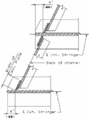
 751.14 lateral bracing detail b.gif 446 × 276; 9 KB
 751.14 lateral bracing detail c.gif 318 × 285; 6 KB
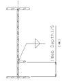 751.14 longitudinal web stiffener.jpg 544 × 713; 28 KB
 751.14 longitudinal web stiffener (one side only).gif 744 × 500; 25 KB
 751.14 part elevation of girder-constant depth-end span.gif 686 × 284; 12 KB
 751.14 part elevation of girder-constant depth-interior span.gif 639 × 239; 7 KB
 751.14 part elevation of girder-variable depth girder.gif 744 × 390; 16 KB
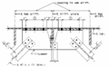
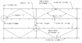 751.14 part lateral bracing framing plan1.gif 631 × 329; 10 KB
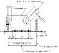
 751.14 plan of end diaphragm connection for steel structures.gif 290 × 391; 8 KB
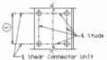 751.14 plan of shear connector unit.gif 244 × 136; 3 KB
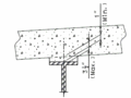
 751.14 section thru haunch showing shear connectors.gif 289 × 145; 4 KB
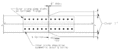
 751.14 spacing of intermediate diaphragms from splice.gif 548 × 466; 10 KB


.gif)
.gif)


_variable_flange_width.gif)


.gif)


.gif)