Uncategorized files
Jump to navigation
Jump to search
Showing below up to 50 results in range #7,471 to #7,520.
View (previous 50 | next 50) (20 | 50 | 100 | 250 | 500)
 751.22 Section Thru Girder 2-6.gif 168 × 278; 5 KB
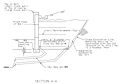
 751.22 Section Thru Girder Type 7.gif 236 × 317; 5 KB
 751.22 Shear Blocks Elevation View.gif 629 × 151; 6 KB
 751.22 Shear Blocks Elevation View Open Diaphragm.gif 526 × 134; 5 KB
 751.22 Shear Blocks Plan View.gif 625 × 133; 3 KB
 751.22 Shear Blocks Plan View Exp Bts Closed Diaphragms.gif 610 × 231; 5 KB
 751.22 Shear Blocks Plan View Exp Bts Open Diaphragms.gif 607 × 179; 4 KB
 751.22 span & structure lengths integral end bents.gif 744 × 500; 25 KB
 751.22 span & structure lengths integral end bents Mar 2011.gif 744 × 500; 25 KB
 751.22 span & structure lengths non integral end bents.gif 744 × 500; 25 KB
 751.22 span & structure lengths non integral end bents Mar 2011.gif 744 × 500; 25 KB
 751.22 standard conc PSI span ranges.gif 707 × 842; 34 KB
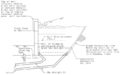
 751.22 Standard PSI Girder End Section.gif 744 × 500; 25 KB
 751.22 Superelevation Slope.gif 372 × 214; 4 KB
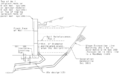
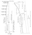
 751.22 Theoretical Slab Haunching Diagram.gif 744 × 500; 25 KB
 751.22 typ continuous PS structure Integral End Bents.gif 744 × 500; 25 KB
 751.22 typ continuous PS structure Non Integral End Bents.gif 633 × 156; 5 KB
 751.22 Vent Holes Elevation & Section.gif 597 × 252; 7 KB
 751.23 double tee curved structure detail.gif 540 × 521; 10 KB
 751.23 double tee diaphragm reinf. for end bent int bent.gif 607 × 225; 8 KB
 751.23 double tee optional constr joint.gif 507 × 471; 7 KB
 751.23 double tee optional constr joint sec aa.gif 344 × 131; 4 KB
 751.23 double tee vent hole details.gif 489 × 150; 4 KB
 751.23 part plan of ps conc dbl tee girder.gif 536 × 346; 7 KB
 751.23 section thru double tee.gif 491 × 189; 4 KB
 751.23 section thru ps conc dble tee girder.gif 535 × 237; 8 KB
 751.23 section thru ps conc dble tee girder detail a.gif 171 × 118; 2 KB
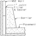 751.24.1.1 barrier front MSE wall-01.jpg 625 × 633; 60 KB
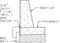 751.24.1.1 barrier top MSE wall-01.jpg 625 × 454; 38 KB
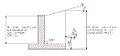 751.24.1.2.jpg 523 × 243; 24 KB
 751.24.1.2 active soil.jpg 356 × 204; 15 KB
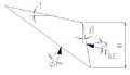
 751.24.1.2 collision profile.jpg 340 × 214; 16 KB
 751.24.1.2 collision section.jpg 435 × 241; 18 KB
 751.24.1.2 live load1.jpg 333 × 219; 18 KB
 751.24.1.2 live load surcharge.jpg 470 × 234; 26 KB
 751.24.1.2 retaining.jpg 248 × 232; 14 KB
 751.24.1.2 surcharge.jpg 481 × 314; 25 KB
 751.24.1.2 wedges.jpg 463 × 345; 26 KB
 751.24.1.2 wheel.jpg 347 × 277; 25 KB
 751.24.2.1.jpg 983 × 395; 46 KB
 751.24.2.1 alternate.jpg 956 × 515; 48 KB
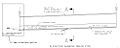
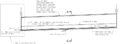 751.24.2.1 elev drain pipe-01.png 996 × 365; 28 KB
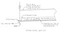
 751.24.2.1 elev drain pipe alt-01.png 876 × 464; 82 KB
 751.24.2.1 section AA.jpg 956 × 670; 62 KB
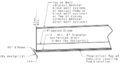
 751.24.2.1 sec A-A-01.png 657 × 409; 19 KB
 751.24.2.1 sec A-A-02.png 708 × 440; 34 KB
 751.24.2.2.jpg 809 × 903; 87 KB
 751.24.2.2 battered.jpg 680 × 698; 31 KB


