617.1 temporary traffic barriers
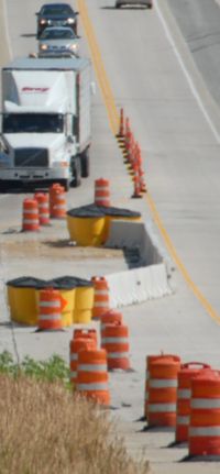
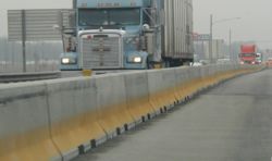
Temporary traffic barrier prevents vehicles from entering the work area or to separate vehicles in temporary two-lane, two-way traffic on normally divided highways. The use of temporary traffic barrier instead of standard temporary traffic control measures is based on engineering judgment. However, temporary traffic barrier is required on roadway excavation edge drop-offs (refer to Standard Plan 619.10), bridge rehabilitation jobs with bridge rail replacement and/or full depth repair, and is to be considered for any other type of long-term bridge repair work. When specified, quantities are calculated and shown on the plans.
Barrier design has several critical components to perform properly:
- 1) Lateral Deflection – The distance that the barrier travels laterally, after an impact, under the guidance of NCHRP 350 or MASH 2016.
- 2) Buffer Area (Lateral) – Normally the area behind the barrier, equal to lateral deflection, that must be free of storage items (material, equipment, etc.) that may hinder the barrier’s crashworthiness.
- 3) Minimum Deployment Length – Minimum length of barrier needed to perform as tested under NCHRP 350 or MASH 2016 criteria.
Appropriate channelizing devices and pavement marking are always used in front of barrier tapers for lane closures, shoulder closures or transition areas for temporary bypasses or connections. Wherever practical, a lateral shy distance is to be provided between the edge of the driving lane and the barrier, and a longitudinal buffer area is to be provided between the channelizer taper and the barrier taper.
At times, the placement of barriers may require a minimum buffer area, since many types of barriers can be anchored on asphalt and concrete pavements to reduce the lateral deflection. Bridge Division and the district core team shall determine and coordinate when anchoring barriers is needed on a particular project. If a particular barrier type and anchoring system is not specified, the plans shall provide guidance of the placement of barrier and the appropriate buffer area needed for the project.
Relocating Temporary Traffic Barrier
When traffic barrier is required to be moved as part of the staging or construction sequence proposed by MoDOT, the appropriate pay item for relocating temporary traffic barrier should be included. Use of the relocating pay item should be limited to the shifting of furnished barrier for traffic switches between phases, but in the same general area. In other words, relocation should only be used when the barrier can be reasonably picked up and re-set with a single piece of equipment. Conversely, if barrier must be loaded and trucked to a new location, separate payment should be provided for “furnishing” at the new location. For example, for a project with 3 bridge deck overlays that requires 600 feet of barrier per bridge, and the barrier must be shifted to the opposite side of centerline between phases, you would set up 1,800 feet of furnishing barrier and 1,800 feet of relocating barrier. This would be the case even if the contract disallowed the bridges to be worked on concurrently. This method is due to the fact that the cost to load and truck barrier is very near the cost of “furnishing”. Also, the summary of quantities table and traffic control plan should clearly demonstrate the designer’s intent for payment of “relocating” barrier vs. “furnishing” barrier (location, length, phase, etc.).
Contractors are not required to paint temporary concrete traffic barriers because delineators are used. Delineators for temporary concrete traffic barriers are provided at no direct pay as shown on Standard Plan 617.20 and stated in Sec 617. Delineator pay items are used only to retrofit existing permanent concrete traffic barrier.
An abbreviated description of several types of barriers are described below. For additional information and standard drawings refer to End Terminal and Barrier Systems.
Contents
617.1.1 Temporary Concrete Traffic Barrier – Type F
The preferred installation method for temporary concrete traffic barrier is freestanding and requires a minimum 2 ft. buffer area behind the barrier to allow for lateral deflection into both work areas and lane separation situations. A buffer area is an unprotected or unshielded area. Freestanding installations when used near unprotected bridge decks (refer to project bridge plans) or open roadway excavations (refer to Standard Plan 619.10) both require 3 ft. buffer area behind the barrier.
On projects where freestanding installations cannot be used and lateral deflection must be limited further, then tie-down straps system, anchor bolt system through deck, or anchor pin system shall be used. (Refer to Standard Plan 617.20.)
On projects with asphalt material tie-down straps system and anchor bolt system cannot be used because of the different bending abilities of the bolts when placed in asphalt compared to concrete. On these projects barriers may be installed with an asphalt barrier pin system as shown in Standard Plan 617.20. The use of asphalt pin system shall have a minimum of 2 in. of asphalt material on concrete and/or soil. The asphalt pad shall be a minimum of 30 in. wide through the pinned down area.
Projects may have freestanding barrier transition into anchored barriers or permanent barriers. The major concern of transitioning freestanding barriers into anchored/permanent barriers is pocketing the vehicle into the barrier system. Each transition situation has a specific design (refer to Standard Plan 617.20).
Pay items are available for Temporary Traffic Barrier, Temporary Traffic Barrier Anchored and Stiffness Transition Section as well as pay items for relocating Temporary Traffic Barrier, Temporary Traffic Barrier Anchored and Stiffness Transition Section.
617.1.2 Alternative Temporary Traffic Barrier
617.1.2.1 10 ft. Cross Bolt Temporary Concrete Barrier
The preferred installation method for this traffic barrier is freestanding and requires a minimum 2 ft. buffer area behind the barrier to allow for lateral deflection in both work areas and lane separation situations. When freestanding installations are used on unprotected bridge decks, a 27 in. buffer area shall be provided for roadway excavation edge drop-offs and equipment and material storage locations. At this time, the 10 ft. Cross Bolt Temporary Concrete Barrier does not have a anchoring system to further reduce the lateral deflection.
617.1.2.2 30-foot Cross Bolt Temporary Concrete Barrier
The preferred installation method for temporary concrete traffic barrier is freestanding and requires a minimum 19 in. buffer area behind the barrier to allow for lateral deflection in both work areas and lane separation situations. When freestanding installations are used on unprotected bridge decks, a 19 in. buffer area shall be provided for roadway excavation edge drop-offs and equipment and material storage locations. At this time, the 30 ft. Cross Bolt Temporary Concrete Barrier does not have a anchoring system to further reduce the lateral deflection.
617.1.2.3. Proprietary Temporary Traffic Barrier
Proprietary temporary traffic barrier (PTTB) may be used in lieu of Type F temporary concrete traffic barrier. When PTTB is used for work areas or lane separation situations, the required buffer area shall be based upon the dynamic deflection exhibited in the manufacture’s crash testing results.
When freestanding installations are used on unprotected bridge decks, a buffer area shall be required based on the NCHRP 350 or MASH 2016 TL-3 dynamic lateral deflection roadway excavation edge drop-offs and equipment and material storage locations. NCHRP 350 or MASH 2016 TL-3 tested anchoring systems may be used to reduce the above buffer area, dependent on manufacturer’s recommendation.
617.1.2.4 Water-Filled Barrier
Besides being just a temporary traffic barrier, water-filled barriers (WFB) have been proven to be a channelization enhancement to the work zone. The core team may consider the use of WFB within urban areas.
The core team may consider using WFB as channelization enhancement to:
- a) Clearly define entrances and exits.
- b) Provide a separation between pedestrian and traveled way in areas of 45 mph or less. For higher speeds, a lateral deflection and buffer area review will be required for the separation of pedestrians and travel way.
- c) Define traffic lanes with a wall separating or keeping the traffic in the proper lanes.
Many WFB systems do not need an end treatment since the WFB system create their own work zone end treatment.
617.1.2.5 Moveable Traffic Barrier System
Moveable Traffic Barrier Systems (MTBS) are barrier segments that can be frequently transferred from one lane to another lane by way of a specialized machine. This system allows quick increases in the directional capacity of the roadway. The optimum use of the MTBS is when work zones will affect the number of lanes for commuting traffic.
Due to the expense, the core team shall perform a benefit/cost study for the use of the system. Since the MTBS use will be minimal, the use of the Moveable Traffic Barrier JSP will need to be inserted into the contract.
617.1.3 Temporary Concrete Traffic Barrier End Treatments
Exposed temporary concrete traffic barrier ends are treated in one of the following methods:
617.1.3.1 Barrier Flare
The barrier run may be flared to the limits of the clear zone. The existing shoulder slope or median slope may be too steep for this type of installation. If this is the case, temporary grading should be provided or a different end treatment should be used. The Roadside Design Guide contains recommended barrier placement in non-level medians. These guidelines also apply to outside shoulders.
617.1.3.2 Barrier Height Transition
A barrier height transition is designed to redirect traffic away from the blunt end of the barrier. A barrier height transition, as shown on Standard Plan 617.20, is installed on the exposed end of the barrier where the posted speed prior to construction on an existing facility is 35 mph or less. When specified, quantities are calculated and shown on the plans.
617.1.3.3 Crash Cushion
Crash cushions are designed to absorb energy of an impacting vehicle and reduce the force on a passenger to an acceptable level. An approved crash cushion is installed on the exposed end of the barrier where the posted speed prior to construction on an existing facility or the anticipated posted speed of a temporary facility is greater than 35 mph. A crash cushion will be required on the upstream end for divided facilities, and on both ends for all two-way facilities. Sand barrels are discussed in EPG 612.2 Sand-Filled Impact Attenuators (Sand Barrels). Applicable pay items are included in the plans. Special provisions are provided in the plans for non-standard devices. The types of crash cushions currently used are as follows:
- 617.1.3.3.1 Impact Attenuators (Sand Barrels). This system consists of a group of freestanding sand barrels and is discussed in EPG 612.2 Sand-Filled Impact Attenuators (Sand Barrels).
- 617.1.3.3.2 Work Zone Crash Cushions. These alternate crash cushions may be used when sufficient width is not available for sand barrels. These are typically used on the ends of temporary two-lane, two-way sections on divided highways. For temporary installations, refer to End Terminals, Crash Cushions and Barrier Systems for a list of approved work zone crash cushions.
617.1.4 Temporary Glare Screens
Temporary glare screens in work zones consist of modular units installed on top of temporary concrete traffic barrier. Temporary glare screens prevent headlight glare. Glare screens may also be used to block the driver’s view of construction activities. Glare screens are not used where they could restrict driver visibility and sight distance. Use of these units are limited due to installation and maintenance concerns to areas where work zone activities could impact the flow of traffic, or geometrics could create a blinding effect on drivers. When specified, quantities are calculated and shown on the plans.


