751.38 Spread Footings
Contents
751.38.1 General
751.38.1.1 Design Criteria
Materials
Concrete
Typically, footings shall consist of:
Class B Concrete (Substructure) = 3.0 ksi = 10
Class B-1 Concrete (Substructure) may also be used in special cases (See Project Manager).
Reinforcing Steel
Minimum yield strength, = 60.0 ksi Steel modulus of elasticity, = 29000 ksi
Limit States
Service Limit State
Settlement and overall stability shall be investigated at the Service Limit State. Overall stability shall be checked where there is a sloped embankment located near the footing.
Strength Limit State
Bearing Resistance and the structural capacity of the footing shall be investigated at the Strength Limit States.
Restricting the amount of eccentricity of the resultant load serves to address the check for overturning.
751.38.1.2 Dimensions
|
|
| SIDE ELEVATION | FRONT ELEVATION |
| Elevations and Standard Variables for Spread Footings | |
| Where: | ||
| D | = | column diameter |
| A | = | edge distance from column |
| Minimum of 12". | ||
| L | = | footing length (3" increments) |
| Minimum of 1/6 x distance from top of beam to bottom of footing. | ||
| B | = | footing width (3" increments) |
| Minimum of column diameter + 2A (3" increments). | ||
| H | = | footing depth (3" increments) |
| Minimum of 30" or column diameter. For column diameters ≥ 48", use a 48" minimum footing depth. | ||
| Maximum of 72". | ||
Footing depths greater than 36 inches require the side faces to have shrinkage and temperature reinforcement.
Size
The size of footing shall be determined by computing the location of the resultant force and by calculating the bearing pressure.
Footing size should be proportioned so that stresses under the footing are as uniform as practical at the service limit state.
Long, narrow footings are to be avoided, especially on foundation material of low capacity. In general, the length to width ratio should not exceed 2.0, except on structures where the ratio of the longitudinal to transverse loads or some other consideration makes the use of such a ratio limit impractical.
Location
If there is scour, erosion, or undermining potential, footings shall be located to bear below the maximum anticipated depth of scour, erosion, or undermining.
751.38.2 Design
751.38.2.1 Resultant Force Location
For eccentrically loaded footings, the location of a resultant vertical force shall be checked.
| Ex. | For the given loads applied to the top of a footing: | |
| Axial Load, | = 800 kips | |
| Moment in Longitudinal Direction, | = 1200 k-ft | |
| Moment in Transverse Direction, | = 1000 k-ft | |
| Then, | ||
| Eccentricity in Longitudinal Direction, | = 1200/800 = 1.5 ft | |
| Eccentricity in Transverse Direction, | = 1000/800 = 1.2 ft | |
| Where: | |
| = eccentricity parallel to dimension B | |
| = eccentricity parallel to dimension L | |
Location of the Resultant Force
The following table represents the allowable resultant force locations for the given soil characteristics.
| Limit State | Soil Type | Resultant Location |
| Strength | Cohesive and granular soil and Intermediate Cohesive Geomaterial |
Middle 1/2 |
| Intermediate Cohesionless Geomaterial and Rock |
Middle 3/4 |
Where:
The middle 1/2 is defined as:
The middle 3/4 is defined as:
751.38.2.2 Bearing Pressure
The footing shall be sized at the Strength Limit State.
Footings on Cohesive and Intermediate Cohesive Geomaterial
For footings with eccentric loads, the area of footing used in calculating the bearing pressure shall be reduced according to the load eccentricities. The reduced area, , within the confines of the physical footing is defined as follows:
- Bearing Pressure for Footing Loaded Eccentrically
| Where: | |
The design bearing pressure on the effective area shall be assumed to be uniform and not the actual contact pressure beneath the footing. The reduced effective area shall be concentric with the load.
The bearing pressure limits shall meet the following equation:
| Where: | |
| = 0.45 (unless Geotechnical Division gives different value) | |
| = factored resistance of geotechnical material | |
| = nominal bearing resistance of geotechnical material | |
| = | |
| = maximum equivalent axial load from applicable Strength Limit State load combinations | |
Footings on Rock or Intermediate Cohesionless Geomaterial
Footings on rock shall be designed assuming a trapezoidal or triangular stress distribution according to the following criteria.
If: , assume a trapezoidal distribution, otherwise assume a triangular distribution.
751.38.2.3 Shear
The footing is to be designed so that the shear strength of the concrete is adequate to handle the shear stress without the additional help of reinforcement. If the shear stress is too great, the footing depth should be increased.
The shear capacity of the footings in the vicinity of concentrated loads shall be governed by the more severe of the following two conditions.
One Way Shear
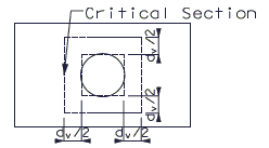
Critical sections shall be taken from the face of the column for square or rectangular columns or at the equivalent square face of a round column. The equivalent square column is the column which has a cross sectional area equal to the round section of the actual column and placed concentrically.
- Critical Section For One Way Shear Design
One Way Shear Capacity,
| = |
Where:
| = 0.9 | |
| = | |
| = footing width | |
| = factor indicating ability of diagonally cracked concrete to transmit tension = 2.0 | |
| = effective shear depth of concrete | |
| = | |
| = the triangular or trapezoidal stress distribution applied to the designated loaded area of the footing from the Strength Load Combinations |
Two Way Shear
The critical section for checking Two Way Shear is taken from the boundary of a square area with sides equal to the equivalent square column width plus the effective shear depth as shown.
- Critical Section For Two Way Shear Design
Two Way Shear Capacity,
| = |
Where:
| = | |
| = ratio of long side to short side of the rectangle through which the concentrated load or reaction force is transmitted. | |
| = perimeter of the critical section = 4*(dv + Equivalent square column width) | |
| = effective shear depth, in. | |
| = maximum axial load on top of footing from column reactions of Strength Load Combinations. |
The following table shows approximate capacities for both One Way and Two Way Shear for the given footing depth and column diameter to assist in selecting a footing length and width.
| Column Diameter FT |
Footing Depth FT |
One Way Shear Capacity, K/FT |
Two Way Shear Capacity, KIPS |
| 2.5 | 2.50 | 30.7 | 1074 |
| 2.5 | 2.75 | 34.3 | 1266 |
| 2.5 | 3.00 | 37.8 | 1473 |
| 2.5 | 3.25 | 41.4 | 1694 |
| 2.5 | 3.50 | 44.9 | 1928 |
| 2.75 | 2.75 | 34.3 | 1327 |
| 2.75 | 3.00 | 37.8 | 1540 |
| 2.75 | 3.25 | 41.4 | 1767 |
| 2.75 | 3.50 | 44.9 | 2008 |
| 2.75 | 3.75 | 48.5 | 2263 |
| 3.00 | 3.00 | 37.8 | 1607 |
| 3.00 | 3.25 | 41.4 | 1840 |
| 3.00 | 3.50 | 44.9 | 2087 |
| 3.00 | 3.75 | 48.5 | 2348 |
| 3.00 | 4.00 | 52.0 | 2624 |
| 3.25 | 3.25 | 41.4 | 1913 |
| 3.25 | 3.50 | 44.9 | 2166 |
| 3.25 | 3.75 | 48.5 | 2434 |
| 3.25 | 4.00 | 52.0 | 2716 |
| 3.25 | 4.25 | 55.6 | 3012 |
| 3.50 | 3.50 | 44.9 | 2246 |
| 3.50 | 3.75 | 48.5 | 2520 |
| 3.50 | 4.00 | 52.0 | 2808 |
| 3.50 | 4.25 | 55.6 | 3110 |
| 3.50 | 4.50 | 59.1 | 3426 |
| 3.75 | 3.75 | 48.5 | 2605 |
| 3.75 | 4.00 | 52.0 | 2900 |
| 3.75 | 4.25 | 55.6 | 3208 |
| 3.75 | 4.50 | 59.1 | 3531 |
| 3.75 | 4.75 | 62.7 | 3868 |
| 4.00 | 4.00 | 52.0 | 2992 |
| 4.00 | 4.25 | 55.6 | 3306 |
| 4.00 | 4.50 | 59.1 | 3635 |
| 4.00 | 4.75 | 62.7 | 3978 |
| 4.00 | 5.00 | 66.2 | 4335 |
| 4.25 | 4.25 | 55.6 | 3404 |
| 4.25 | 4.50 | 59.1 | 3740 |
| 4.25 | 4.75 | 62.7 | 4089 |
| 4.25 | 5.00 | 66.2 | 4452 |
| 4.25 | 5.25 | 69.8 | 4830 |
| 4.50 | 4.50 | 59.1 | 3844 |
| 4.50 | 4.75 | 62.7 | 4200 |
| 4.50 | 5.00 | 66.2 | 4569 |
| 4.50 | 5.25 | 69.8 | 4953 |
| 4.50 | 5.50 | 73.3 | 5351 |
| 4.75 | 4.75 | 62.7 | 4310 |
| 4.75 | 5.00 | 66.2 | 4686 |
| 4.75 | 5.25 | 69.8 | 5076 |
| 4.75 | 5.50 | 73.3 | 5481 |
| 4.75 | 5.75 | 76.8 | 5899 |
| 5.00 | 5.00 | 66.2 | 4803 |
| 5.00 | 5.25 | 69.8 | 5200 |
| 5.00 | 5.50 | 73.3 | 5610 |
| 5.00 | 5.75 | 76.8 | 6035 |
| 5.00 | 6.00 | 80.4 | 6474 |
| 5.25 | 5.25 | 69.8 | 5323 |
| 5.25 | 5.50 | 73.3 | 5740 |
| 5.25 | 5.75 | 76.8 | 6171 |
| 5.25 | 6.00 | 80.4 | 6616 |
| 5.50 | 5.50 | 73.3 | 5869 |
| 5.50 | 5.75 | 76.8 | 6306 |
| 5.50 | 6.00 | 80.4 | 6758 |
| 5.75 | 5.75 | 76.8 | 6442 |
| 5.75 | 6.00 | 80.4 | 6900 |
| 6.00 | 6.00 | 80.4 | 7042 |
Assumptions:
| = 0.9 | |
| = 3 KSI | |
| = 2.0 | |
| = footing depth - 4" |
One Way Shear Capacity = 0.0316
One Way Shear capacity is per foot width of footing.
- i.e. Total
Two Way Shear Capacity =
751.38.2.4 Moment
The critical section for bending shall be taken at the face of the equivalent square column. The applied moment shall be determined from a triangular or trapezoidal stress distribution on the bottom of the footing.
The bearing pressure used to design bending reinforcement shall be calculated from Strength I, III, IV, and V Load Combinations.
Reinforcement must meet the maximum and minimum requirements as given in LRFD 5.7.3.3.1 and LRFD 5.7.3.3.2.
The minimum reinforcement allowed is #5 bars spaced at 12”.
Distribution of Reinforcement
Reinforcement in the long direction shall be distributed uniformly across the entire width of footing.
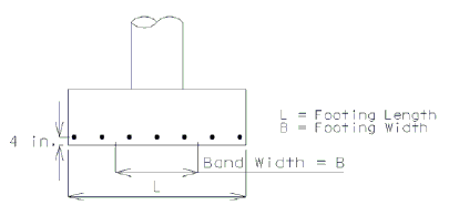
For reinforcement in the short direction, a portion of the total reinforcement shall be distributed uniformly over a band width equal to the length of the short side of footing and centered on the centerline of column or pier as shown below.
The band width reinforcement required shall be calculated by the following equation:
| = | |
| Where: | |
| = area of steel in the band width, in.2 | |
| = total area of steel in short direction, in.2 | |
| = ratio of the long side to the short side of footing | |
Distribution of Reinforcement in Spread Footing
The remainder of the reinforcement required in the short direction shall be distributed uniformly outside the center band width of footing.
Crack Control Reinforcement
The reinforcement shall meet the spacing criteria, s, as specified.
Where:
| = concrete cover measured from extreme tension fiber to center of flexural reinforcement, in. | |
| = tensile stress in reinforcement at the service limit state, ksi | |
| = depth of footing, in. | |
| = 1.0 for Class 1 exposure condition |
751.38.3 Details
751.38.3.1 Reinforcement
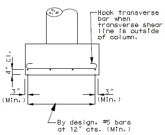
|
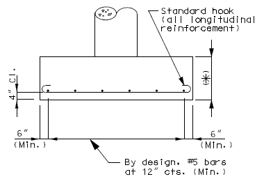
|
| FRONT ELEVATION | SIDE ELEVATION |
(*) Footing depths > 36 in. may require the side faces to have shrinkage and temperature reinforcement, See Structural Project Manager.


