106.3.2.8 TM-8, Photometric Test for Measuring the Brightness of Reflective Sheeting
This method describes the apparatus and procedure used to determine the brightness of reflective materials.
Contents
106.3.2.8.1 Apparatus
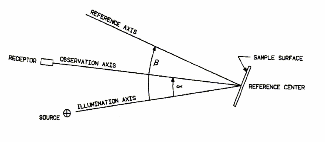
The apparatus for this test (Figure 106.7.8) consists of a light source that projects a beam of uniformly intense light encompassing the reflective material at a distance of 15 ± 0.01 meters. The intensity of this projected beam is measured with a photoreceptor and is called the incident light. The test samples are fastened to and centered on a vertical panel that can be rotated about a horizontal axis in the plane of the sample. This rotation about the horizontal axis is calibrated and adjustable for the required entrance angles.
The photoreceptor is mounted on a movable holder adjacent to the end of the light source. The center of the photoreceptor is placed at such a distance from the axis of the light source that the photoreceptor shall receive a beam of divergent rays, the central axis of which forms the desired observation angle (0.1°, 0.2°, etc.) with the central axis of the incident beam.
The photometric unit is mounted in a dark, black-walled room in which stray light has been cut to a minimum. At no time are rays or reflections from the light source allowed to fall directly on the photoreceptor or any point immediately in front of the plane of its face.
106.3.2.8.2 Calibration
Place the crosshatched mirror on the mounting plate of the goniometer and adjust the B1 and B2 axis until the image of the cross aligns with the light source. Remove the mirror and replace it with the photoreceptor. Cover and zero the photoreceptor, then set the control unit to the least sensitive range. Remove the cap and adjust the gain until the value is 1900 ± 0.5. Turn off the photoreceptor, unplug the AC cord and place the control unit and the photoreceptor back on the observation angle positioner. Do not disturb the gain and zero knobs during the move. The National Institute of Standards and Technology (NIST) traceable standard is now placed on the goniometer, the appropriate angles set and the reading taken. The coefficient of retroreflection is then computed and compared with the values of the NIST Standard.
106.3.2.8.3 Procedure
After the equipment is turned on and allowed to warm up for 15 minutes, calibrate and proceed as follows:
The photoreceptor is adjusted to the desired observation angle (0.2°, 0.5°, etc.). The sample is placed in the sample holder and adjusted to give the desired entrance angle. The reflected light is then measured and recorded. To obtain the net reflection value of the sample, a correction for ambient light is subtracted from the readings taken on the sample. This correction for ambient light is obtained by recording the meter reading of the test stand before any samples are placed in the sample holder.
106.3.2.8.4 Calculation
- R = (MT) d2 / MS
- RA = (MT - MD) d2 / MSA
- RL = (MT - MD) d2 / MS A cos (ß - α) x 1000
Where:
- R = Coefficient of Luminous Intensity in candelas per lux.
- RA = Coefficient of retroreflection in candelas per lux per square meter.
- RL = Specific Luminance in millicandelas per lux per square meter.
- MT = Reading of sample measured at the observation position.
- MD = Background reading.
- d = Test distance in meters.
- MS = Mean reading of the source measured normal to the source at the sample position.
- A = Area of sample in square meters.
- ß = Entrance Angle
- α = Observation Angle
106.3.2.8.5 Equipment
Model 940 Advanced Retro Technology Inc. Photometric Range System consisting of:
- Model 950 Angle Observation Positioner with a range of 0.1° to 2.0°.
- Model 960 Three Axis Goniometer, beta 1 and beta 2 entrance angles and epsilon for rotational angles.
- Model 970 Photoreceptor having a photopically corrected solid state detector with three ranges.
- Model 980 Projection Light Source having a uniformity of illuminance of ± 3% with a correlated color temperature of 2856K ± 20K and a flux output variation less than ± 1%.
- Horizontal mounting plate for lane marking tape, raised pavement markers and barrier delineators.
