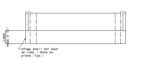
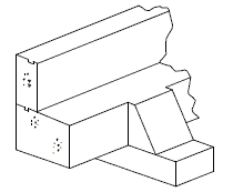
751.30 Open Concrete End Bents
Jump to navigation
Jump to search
751.30.1 Details
751.30.1.1 Stub Bents (Non-Integral)
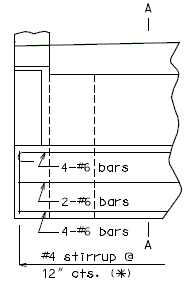
|
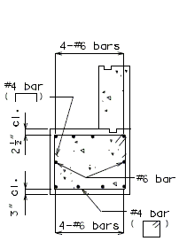
|
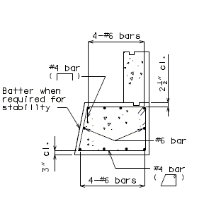
|
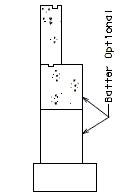
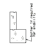
| Part Elevation | Section A-A | Section A-A |
|---|---|---|
| Stub Bent Embedded in Rock | ||
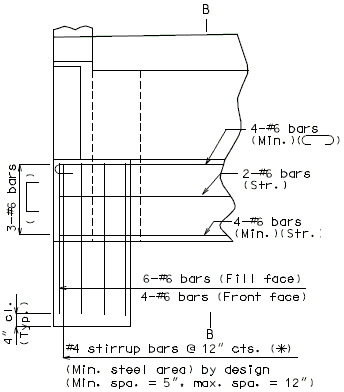
|
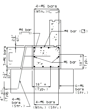
|
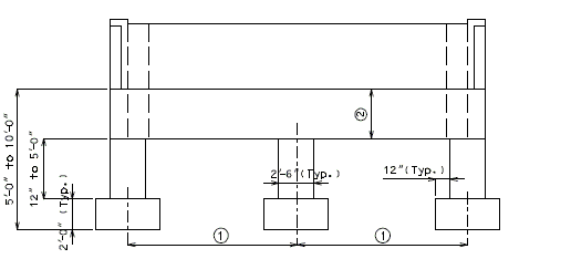
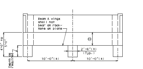
| Part Elevation | Section B-B |
|---|---|
| Stib Bent on Long Footings | |
751.30.1.2 Stub Bents (Sliding Integral)
Stub Bent (Sliding Integral) Abutments should not be used without consulting with the Structural Project Manager.
Generally pile supported integral abutments are desirable and coring to achieve 10 feet unsupported length from the bottom of the abutment beam to rock should be investigated. Eight feet unsupported length would be acceptable for short bridges. Cost comparison should be performed to compare the use of a Stub Bent Integral Abutment with the use of oversized drilled holes and pile supported Integral Abutment.
The Stub Bent Integral Abutment is a stiffer abutment than a pile supported integral abutment and the following issues should be considered:
- If a bridge has both a stub bent integral abutment and a pile supported integral abutment, it is unlikely that thermal movement will equally be divided by the two end bents. The pile supported integral end bent would be expected to experience more than half of the bridge thermal movement. (If bridge grade slopes down toward the pile end bent, then the pile integral end bent may experience most all of the thermal movement.)
- Maximum slope of bridge should be 5%; however, smaller slope is desirable.
- Maximum bridge skew of 30 degrees.
- Avoid using for curved structures where curvature effects must be considered.
- The length of the wingwalls may distort movement of the abutment. The wingwalls may both prevent movement if they are long or one wingwall may distort movement if the bridge is skewed. Stub Bent Integral Abutments should not be used with long wingwalls.
- Minimize the abutment beam height.
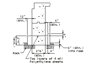
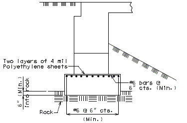
- Two polyethylene sheets (4 mil) between the bottom of the abutment beam and top of the footing are preferred to roofing felt.
- Provide an earth bench near superstructure to minimize abutment depth and wingwall length.
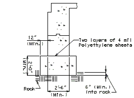
|
|
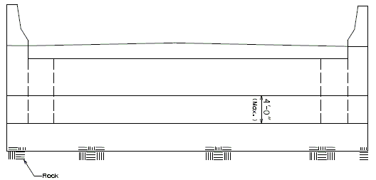
| Section at Centerline Bent | Elevation 1 |
|---|---|
|
|
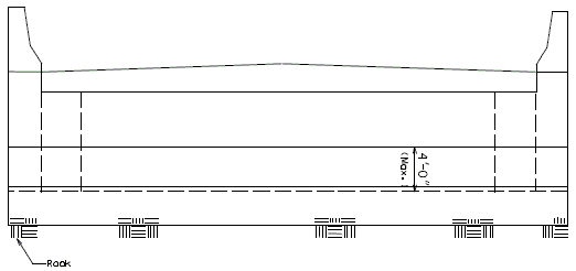
| Section at Centerline Bent | Elevation 2 |
| (Seismic Detail) | |
| Bent without Seismic Details | |
| |
| Stub Bent on Rock | |
| Bent including Seismic Details | |
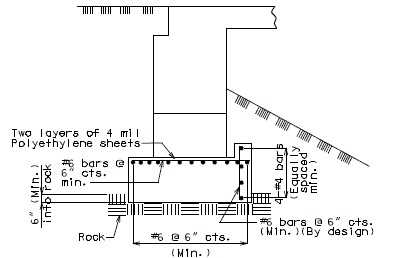
| |
| Stub Bent on Rock | |
