Category:1029 Fabricating Prestressed Concrete Members for Bridges
This article establishes procedures for inspectioning and reporting precast prestressed bridge members. Reinforcing steel and portland cement concrete for use in prestressed members are to be inspected in accordance with the applicable articles of the Engineering Policy Guide. Refer to Sec 1029 for MoDOT’s specifications.
Contents
- 1 1029.1 Apparatus
- 2 1029.2 Procedure
- 2.1 1029.2.1 Materials
- 2.2 1029.2.2 Equipment
- 2.3 1029.2.3 Forms
- 2.4 1029.2.4 Holes
- 2.5 1029.2.5 Stressing Requirements
- 2.6 1029.2.6 Prestressing Steel Strand
- 2.7 1029.2.7 Placement of Reinforcement
- 2.8 1029.2.8 Placing and Consolidating Concrete
- 2.9 1029.2.9 Curing
- 2.10 1029.2.10 Form Removal
- 2.11 1029.2.11 Surface Finish
- 2.12 1029.2.12 Prestress Transfer
- 2.13 1029.2.13 Inspection of Completed Members
- 2.14 1029.2.14 Handling, Storing and Transporting
- 2.15 1029.2.15 Bond Breaker
- 2.16 1029.2.16 Request for Acceptance of Incorrectly Fabricated or Damaged Members
- 2.17 1029.2.17 Approved Standard Repairs
- 2.18 1029.2.18 Records
- 3 1029.3 Report (Records)
- 4 1029.4 Figures
1029.1 Apparatus
- (a) Rule and tape with suitable graduations to accurately measure the material to be inspected.
- (b) OK - MoDOT stamp.
- (c) Weather-resistant marking materials.
| MGS Information |
| Current General Services Specifications (MGS) By Subject |
- (d) Air meter, slump cone and scoop or small shovel for sampling concrete.
- (e) Concrete thermometer.
- (f) Surface thermometer.
- (g) Field Lab in accordance with Sec 106.4.4.
1029.2 Procedure
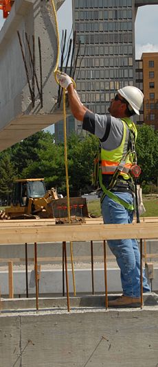
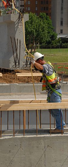
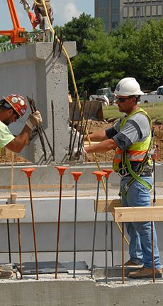
Bridge members vary from project to project and bridge to bridge. The inspector should thoroughly familiarize himself with the plans, specifications and special provisions pertaining to the particular project and bridge members to be inspected prior to fabrication. Sec 1029.6.1 requires the contractor to submit shop drawings for approval to the State Bridge Engineer showing in detail the procedure proposed for the fabrication of the members. Such detail as methods and sequence of stressing and releasing stress in the strands is required to be shown on the shop drawings. The inspector is to become thoroughly familiar with the approved shop drawings.
|
|
|
|
The inspector shall ensure that certifications required by Sec 1029.4 have been submitted and are proper and applicable. There shall be no changes or deviations from the approved plans, drawings or the specifications without written approval from the State Construction and Materials Engineer or shop drawing approved by Bridge. The inspector should ensure that the District Construction and Materials Engineer in charge of inspection at the fabricating plant is notified in writing of all such changes. Before any stressing or fabrication begins, the inspector shall review with the fabricator the plans, specifications and inspection procedures to be used with the objective of avoiding any misunderstanding during the progress of the work. Adequate safety measures shall be taken to prevent injuries to personnel due to the breakage of strands or failure of anchorage devices during the tensioning operations. Inspection shall be refused at any plant where adequate safety measures are not provided and maintained. The inspector shall abide by the safety rules established by the producer, provided that they do not interfere with the inspector's normal duties.
1029.2.1 Materials
The inspector shall ensure that only inspected and approved materials are used in the fabrication of prestressed concrete members.
Prestressing tendons shall be uncoated seven-wire low relaxation strands conforming to AASHTO M 203, Grade 270. Prestressing strands may be accepted on the basis of a manufacturer's certification certifying that the material meets the requirements of AASHTO M 203 or M 204, as required by the contract. The certification must be accompanied by three copies of the mill test report giving results of physical tests on the material furnished and, for material meeting the requirements of AASHTO M 204, a complete chemical analysis. The strand may also be accepted based on the observation of physical tests, and for material meeting the requirements of AASHTO M 204, a mill test report giving a complete chemical analysis. Regardless of the method of acceptance used, the contractor shall furnish three copies of the stress-strain curve representative of the lot to be used. The inspector shall carefully examine all required certifications and material to ensure that they are applicable and show conformance with the specifications. The certifications shall show the lot number and the material shall be tagged for identification purposes. Samples for physical testing shall be obtained and tested at the manufacturer's plant or an approved commercial testing laboratory in the presence of MoDOT personnel. Prestressing strand may be submitted to the Laboratory at the discretion of the District Construction and Materials Engineer. When strand is accepted by certification, a minimum of one check sample per month of each size for each manufacturer of strand being used shall be submitted to the Laboratory for testing. A sample of prestressing strand shall consist of two pieces of strand, each a minimum of 5 ft. (1500 mm) long. The ends of the strand shall be tied, clamped, fused, or otherwise secured to prevent unwinding or fraying during shipment. All pertinent information should be reported through AASHTOWARE Project (AWP).
Structural steel and high-tensile strength alloy bars are accepted on the basis of field inspection and manufacturer's certification stating that the material meets the requirements of the specifications. The certification shall be accompanied by one copy of the mill test report giving chemical analysis and results of physical tests on the material furnished. The inspector shall carefully examine the certifications and the material to ensure that they are applicable and show compliance with the specifications. The certification shall show the lot number and the material shall be tagged for identification purposes. Field inspection shall consist of measurements to determine compliance with the dimensions shown on the plans. ASTM A706 steel can be substituted for Grade 40/60 steel, per EPG 1036.2 Exceptions, Mill Test Reports, Sampling and Record Keeping.
1029.2.2 Equipment
Prestressing equipment, end anchorages and concrete testing equipment shall be carefully examined by the inspector to ensure that the requirements of Sec 1029.5 are met. Calibration of the gauge will be accomplished with the gauges connected to the jacking system to be used in the prestressing operation. The load shall be acting on the ram of the jack and in the same direction as during the tensioning operation. The inspector shall be certain that the proper graphs or tables for the gauges and jacks being used comply with the requirements of Sec 1029.5.1. Pressure gauges should have a full capacity of approximately twice their normal working pressure. The loads to be gauged should not be less than one-fourth or more than three-fourths of the total graduated capacity unless calibration data clearly establish consistent accuracy over a wider range. The gauge pointer on hydraulic gauges must remain steady and not fluctuate until the jacking load can be read and released from the tendon.
1029.2.3 Forms
The inspector shall ensure that forms and formwork comply with the applicable requirements of Sec 1029.6.2. Casting beds shall be checked periodically for deviations from a plane surface sufficient to cause irregularities in the bearing area of the beams or other irregularities that may approach or exceed established tolerances.
Forms, bulk heads, spacers, spreader bars, templates and other equipment having a bearing upon accuracy of dimensions and trueness of lines of the completed beams shall be checked periodically. They shall be clean and free of hardened concrete. Extreme care shall be exercised to prevent form oil from coming into contact with the strands and reinforcement. Hold-up and hold-down devices must be attached in such a manner as to maintain the specified center-to-center spacing of strands in both the vertical and horizontal directions. Clamps, bolts or other devices connecting the bulkhead to the side forms, inserts, blockouts, etc. should be capable of being removed or loosened before steam curing is applied. The casting bed should have a concrete deck on which the forms may be adequately centered, aligned and leveled to the same plane.
1029.2.4 Holes
Plastic or metal conduit may be used to create holes in a member as required by the plans. If metal conduit is used and will remain in the completed member, it must be galvanized.
The inside diameter of conduit that will remain in the completed member must be the size of the required hole. If the conduit will be removed, the diameter of the resulting hole must be the size of the required hole.
The conduit must be securely fastened to the reinforcing steel system to prevent movement during the placing of concrete. Additional reinforcing steel may be used to assist in the placement and fastening of the conduit. The conduit shall not be welded to required reinforcing steel or stressing strands. However, welding the conduit to additional reinforcing steel that will then be tied to the required reinforcing steel system may be acceptable. The methods used to place and fasten conduit in the member shall be detailed in the shop drawings for review.
1029.2.5 Stressing Requirements
The inspector shall ensure that the prestressing tendons are accurately placed and securely held during the placing and curing of concrete. All tensioning of strands shall be performed in the presence of the inspector. No tensioning of strands shall be permitted when the temperature of the strand is below 30° F (-1° C). In all methods of tensioning, the stress induced in the prestressing strand shall be measured both by jacking gauges and by elongation. Tensioning may be done to calculated gauge pressure using elongation as a check. Elongation should be measured to within 1/16 in. (1 mm). Pressure gauge readings at the time of the measured net elongation should be within ± 5 percent of the calculated gauge reading for that particular elongation. If the gauge readings vary more than 5 percent from their calculated reading, all work should be stopped and corrections made before proceeding. Elongations shall make appropriate allowance for temperature, chuck slippage and relaxation of the anchorage. Jacking pressure shall make appropriate allowance for temperature, live-end chuck-slippage, and relaxation of the anchorage (or bed shortening for a self-stressing bed). Live-end chuck slippage shall be determined as described in Sec 705.3.5.1. Elongation shall be within ± 5 percent of that specified upon completion of stressing operations. Specified elongation is calculated using the design load as shown on the approved shop drawings. Independent references should be established adjacent to each anchorage to indicate any yielding or slippage that may occur between the time of initial stressing and final release of cables. Stressing of strands may be from one end unless otherwise indicated in the contract or on the approved shop drawings. Draped strands may be tensioned by either partially jacking from the end of the bed followed by raising or lowering the strands to their final position or entirely by jacking with the strands being held in their draped position during the jacking operation. When the strands are tensioned in their draped position, they should be supported by free-turning rollers at all hold-up and hold-down points. A discrepancy of more than 5 percent between stresses in the strand or tendon as computed from the elongation measurement and those indicated by gauge readings should be cause for jacking from both ends. When attempts by jacking at both ends fail to attain the required elongation, the number of deflection points on the bed shall be reduced or the hardware shall be improved to reduce friction. When strands are deflected after partial tensioning, the strands should be raised or depressed simultaneously at all points or in an approved specific sequence. Several members may be cast in one continuous line, provided that all members are fabricated without undue intervening delay. The time intervening between the casting of the first and last member on a bed shall not exceed 4 days unless otherwise permitted by the engineer. When the temperature at the time of tensioning is such that correction must be made to compensate for change in strand stresses, all members on the bed shall be cast in a continuous pour. The manufacturer may elect to heat the bed, anchorage, and strands in cold weather situations to avoid a continuous pour. The casting of the first and last member on the bed still shall not exceed 4 days and the steel temperature variation shall not exceed 30° F. The tension in the strand as determined from the elongation at the time of placing concrete shall be within 5 percent of that required. The amount of stress to be given each strand shall be as shown on the plans. Tensioning shall be by either the single strand or multi-strand jacking method. Each strand shall be brought to a uniform initial tension as shown in the tensioning schedule on the approved shop drawings. The initial tension on each strand shall be accurately measured by a dynamometer or other approved means. The initial tension should be within 50 pounds (200 N) or 5 percent of that required, whichever is the larger. The initial tension shall be between 5 and 25 percent of the design load as shown on the approved shop drawings. The initial tension should be enough to remove the slack from the strand so that a point can be established for elongation measurement that is valid but not too excessive as to eliminate too much of the elongation which will take place to reach the final load. The same jack used for single strand tensioning may be used for initial tensioning provided it is equipped with proper gauging systems for measuring the initial tension. Measurement of elongation shall not begin until initial tensioning has been completed. When the initial tensioning force is applied to the tendon, reference points for measuring the elongation due to additional tensioning forces must be established. One method of establishing reference points for elongation is use of masking tape. Short sections of tape are wrapped around the strand a predetermined distance from the end anchorage while the initial stress is being applied. Further stress measurements can then be made from the edge of the tape. Any other marking device that provides a sharply defined reference line could be used. Strands passing through stirrups, spirals, headers, hold-ups or hold-downs should be carefully inspected to guard against unusual bindings that would result in substantial restraint. When excessive friction is suspected and especially when tensioning strand in the draped position, checks should be made to ensure that tension is uniform throughout the bed. One method is using masking tape to mark a known length of strand near each end of the bed and one near the center. These lengths should be as long as practical. The elongation in these predetermined sections should be within 5 percent of that specified when computed using the design load as shown on the approved shop drawings.
An example for verifying that the elongation upon completion of the stressing operations is within ± 5 percent of that specified is as follows:
- Specified elongation = PL/AE
Where:
- P = Design load as shown on the plans
- L = Distance in inches from anchorage to reference point
- A = Area of one strand
- E = Modulus of elasticity of steel strand determined from the test report
Elongation upon completion of stressing
- = Seated Elongation – 1/2 measured anchorage movement (or bed shortening for self stressing beds) – measured dead end chuck slippage.
% Deviation = 100 x ((EL - SE)/SE)
Where:
- EL = Elongation upon completion of stressing
- SE = Specified elongation
English example
For this example:
- P = 31,000 lbf
- L = 3,600 in.
- A = 0.153 sq. in.
- E = 28,300,000 psi Seated elongation = 26.00 in.
- 1/2 measured anchorage movement = 0.25 in.
- Measured dead end chuck slippage = 0.125 in.
Therefore:
- Specified Elongation (SE) = (31000 x 3600)/ (.153 x 28,300,000)
- = 25.774 in.
Elongation upon completion of stressing (EL) = 26.00 - .25 - .125 = 25.625 in.
- % Deviation = 100 x ((25.625 – 25.774)/ 25.774)
- = -0.6%
A negative % deviation indicates the strand is understressed. A positive % deviation indicates the strand is overstressed.
SI (Metric) example
For this example:
- P = 137800 N
- L = 91500 mm
- A = 100 mm2
- E = 20000 MPa
- Seated elongation = 660 mm
- 1/2 measured anchorage movement = 6 mm
- Measured dead end chuck slippage = 3 mm
Therefore:
Specified Elongation(SE) = (137800 x 91500)/ (100 X 20000)
- = 630 mm
Elongation upon completion of stressing (EL) = 660 - 6 - 3 = 651 mm
- % Deviation = 100 x ((651 – 630)/ 630)
- = -3.3 %
A negative % deviation indicates the strand is understressed. A positive % deviation indicates the strand is overstressed.
Live End Chuck Slippage
One method of determining the amount of chuck slippage is to place Styrofoam doughnuts or similar devices on the strand inside the anchorages. These devices will ride the strand during tensioning until stopped by the pull plate then ride the strand back as slippage occurs. By measuring the distance between the pull plate and the doughnut the amount of slippage can be determined.
1029.2.6 Prestressing Steel Strand
All strands must be free of contaminates such as dirt, oil, paint, wax, corrosion or other foreign material that may prevent bond between the strands and the concrete. Strands that have been previously tensioned one time may be used providing that they are properly identified, have not been stressed in excess of 80 percent of ultimate strength, and comply with all the applicable requirements of the specifications. The use of prestressing strands having kinks, bends, nicks, or other defects shall not be permitted. A light coating of rust shall not be cause for rejection providing that the loose rust is removed and the surface of the strands is not visibly damaged. Pretensioned steel should always be checked for substances injurious to bond development after tensioning. Tensioned strands should be protected against excessive temperatures such as those produced by torches, welding equipment, or sparks. The strands must be positioned within the dimensions shown on the approved shop drawings. Strands tensioned as a group shall have the same initial tension, be from the same manufacturer, and have essentially the same modulus of elasticity.
1029.2.6.1 Strand Splices
One approved splice per strand may be permitted provided the splices are located outside of the prestressed member. For single strand tensioning, the number of strands per bed that may be spliced is not restricted. When multi-strand jacking is used, either all strands should be spliced or not more than 10 percent of the strands should be spliced. Spliced strands shall be similar in physical properties, from the same manufacturer, and shall have the same twist or lay. If two opposing lays are joined, the splice will rotate resulting in considerable stress loss in the strand.
1029.2.6.2 Wire Failure
Wire failures may be accepted provided not more than one wire in any strand is broken and the area of broken wires does not exceed 2 percent of the total area of the strands. Strands with broken wire should be pulled to the same elongation but not the same load as strands with no broken wire. Stressing to the same load will result in stresses approaching or exceeding 80 percent of the ultimate strength of the strand. If a wire fails during stressing and the elongation is exceeded, a check should be made using the reduced area to ensure that the resulting elongation has not produced stress in excess of 80 percent of the ultimate strength of the strand. Double Tee Girders are to be considered as a unit.
1029.2.6.3 Elongation Computations (English Units)
It is the responsibility of the contractor to compute the required elongation and furnish a copy of the computations to the inspector. It is the inspector's responsibility to check the accuracy of these computations. The length of the strand to be used in calculating elongations shall be the actual length of the strand along its trajectory between the fixed anchorage and the reference point at the jacking end of the strand. It is imperative that the actual dimensions of the bed layout and locations of hold-up and hold-down points agree with the dimensions shown on the approved shop drawings within allowable tolerances. Stress losses due to slippage of strand anchorages and movement of anchorage abutments must be accounted for in the elongation computations. Occasional checks for slow slippage of the chucks should be made to ensure that the required stresses are being maintained. The following example is a typical problem:
- ε = elongation in inches = PL/AE
- P = tension force in pounds
- L = distance in inches from anchorage to reference point
- A = Area of one strand, in.2
- E = modulus of elasticity of steel strand determined from the test report, 28,300,000 psi
- Initial Tension = 3000 lbf.
For this problem:
- P = 31,000 lbf (Total) - 3,000 lbf (Initial)
- = 28,000 lbf (Net)
- L = 300 ft. x 12 in./ft
- = 3600 in.
- A = 0.153 sq. in.
- ε = (28,000 X 3600)/(0.153 X 28,300,000)
- = 23.28 in.
0.37 in. slippage in strand anchorages (0.31 in live end slippage + 0.06 dead end slippage) and 0.25 in. one-half of total horizontal movement of anchoring abutments are assumed based on past plant experience. Then, total elongation required after initial tensioning to leave 31,000 lbs. in the strand equals:
- 23.28 in. + 0.37 in. + 0.25 in. = 23.90 in.
Changes in the ambient temperature after steel tensioning will result in stress changes in the tendons. If steel is stressed in a cold atmosphere and warm concrete is placed around it, there will be a reduction in the tension due to the thermal expansion of the steel. Corrections for steel temperature variation in excess of 30° F shall be made by initial overstressing. At the engineer’s discretion, corrections may be required for lower temperature variations. Where required overstressing exceeds 80 percent of the ultimate strength of the strand, the State Construction and Materials Engineer, should be consulted. The amount of strand under tension that will not be subjected to elevated temperatures while the concrete is undergoing its initial set should be considered in the computations. Thermal correction is not used on self-stressing beds. A self-stressing bed is a bed where abutments are not fastened to footings, allowing horizontal movement. This will allow abutments and forms to expand or contract at the same rate as the strand.
An example of computations for temperature correction is as follows:
Assume for the previous example of elongation computations that the strands are stressed at a strand temperature of 35° F and that the concrete at placement was expected to have a temperature of 77° F.
- P = 31,000 lbf. (Total) - 3,000 lbf. (Initial)
- = 28,000 lbf. (Net) L = 300 ft. x 12 in./ft
- = 3600 in.
- A = 0.153 sq. in.
- ε = 23.28 in.
Length of strand that is not subject to elevated temperature from either concrete or applied heat = 50 ft. = 600 in.
- Thermal coefficient of expansion of steel = 0.0000065 in./in./°F.
- Total length change strand due to temperature elevation
- = 0.0000065 in. x (3600 in.-600 in.) x (77° F -35°F)
- = 0.82 in.
- Total elongation = 23.28 in. + 0.82 in.
- = 24.10 in.
Then total elongation necessary to leave 31,000 lbf in strand = 24.10 in. + 0.25 in. +0.37 in.
- = 24.72 in.
An example of computations for force when stressing:
- Force per in. = P/ε = 28,000/23.28
- = 1202.75 lbf./in.
Force for live end slippage + temperature correction + 1/2 anchorage movement (or bed shortening)
- = (0.31 + 0.82 + .25) x 1202.75 = 1660 lbs.
Total load = specified load + force for live end slippage + temperature correction
- = 31,000 + 1660
- = 32,660 lbf
Similar corrections should be made if stressing is done on a very warm day. The temperature of the steel on beds may approximate 110° F on a warm day, while the concrete temperature may be in the range of 70° F to 75° F. The resulting reduction in the steel temperature will result in an increase of tensile stresses in the steel. One is usually able to predict the temperature of the fresh concrete with sufficient accuracy to calculate the temperature change expected on the steel at the time the concrete is placed.
1029.2.6.4 Elongation Computations (Metric (SI) Units)
This example is not a numeric duplicate of the English version.
It is the responsibility of the contractor to compute the required elongation and furnish a copy of the computations to the inspector. It is the inspector's responsibility to check the accuracy of these computations. The length of the strand to be used in calculating elongations shall be the actual length of the strand along its trajectory between the fixed anchorage and the reference point at the jacking end of the strand. It is imperative that the actual dimensions of the bed layout and locations of hold-up and hold-down points agree with the dimensions shown on the approved shop drawings within allowable tolerances. Stress losses due to slippage of strand anchorages and movement of anchorage abutments must be accounted for in the elongation computations. Occasional checks for slow slippage of the chucks should be made to ensure that the required stresses are being maintained. The following example is a typical problem:
- ε = elongation in millimeters = PL/AE
- P = tension force in Newtons
- L = distance in millimeters from anchorage to reference point
- A = Area of one strand, mm2
- E = modulus of elasticity of steel strand determined from the test report, 200000 MPa
- Initial Tension = 13300 Newtons.
For this problem:
- P = 137800 N (Total) - 13300 N (Initial)
- = 124700 N (Net)
- L = 91.5 m x 1000 mm/m
- = 91500 mm
- A = 100 mm2
- Ε = (124700 x 91500)/(100 x 200000)
- = 570 mm
10 mm slippage in strand anchorages (8 mm in live end slippage + 1.5 mm dead end slippage) and 6 mm one-half of total horizontal movement of anchoring abutments are assumed based on past plant experience. Then, total elongation required after initial tensioning to leave 138000 N in the strand equals:
- 570 mm + 10mm + 6 mm = 586 mm
Changes in the ambient temperature after steel tensioning will result in stress changes in the tendons. If steel is stressed in a cold atmosphere and warm concrete is placed around it, there will be a reduction in the tension due to the thermal expansion of the steel. Corrections for steel temperature variation in excess of 15° C shall be made by initial overstressing. At the engineer’s discretion, corrections may be required for lower temperature variations. Where required overstressing exceeds 80 percent of the ultimate strength of the strand, the State Construction and Materials Engineer, should be consulted. The amount of strand under tension that will not be subjected to elevated temperatures while the concrete is undergoing its initial set should be considered in the computations.
Thermal correction is not used on self-stressing beds. A self-stressing bed has abutments that are not fastened to footings, allowing horizontal movement. This will allow abutments and forms to expand or contract at the same rate as the strand.
An example of computations for temperature correction is as follows:
Assume for the previous example of elongation computations that the strands are stressed at a strand temperature of 2° C and that the concrete at placement was expected to have a temperature of 25° C.
- P = 138000 N (Total) – 13300 N (Initial)
- = 124700 N (Net)
- L = 91.5 m x 1000 mm/m
- = 91440 mm
- A = 100 mm2
- ε = 570 mm
Length of strand that is not subject to elevated temperature from either concrete or applied heat = 15.24 m = 15240 mm
Thermal coefficient of expansion of steel = 0.0000117 mm/mm/°C
Total length change strand due to temperature elevation
- = 0.0000117 x (91500 - 15240) x (25° C - 2° C)
- = 20 mm
Total elongation = 570 mm + 20 mm
- = 590 mm
Then total elongation necessary to leave 137888 N in strand = 590 mm + 6 mm + 10 mm
- = 606 mm
An example of computations for force when stressing:
- Force per mm = P/ε = 124700/570
- = 219 N/mm
Force for live end slippage + temperature correction + 1/2 anchorage movement (or bed shortening)
- = (8 mm + 20 mm + 6.23 mm) x 219 = 7446 N
Total load = specified load + pressure for live end slippage + temperature correction
- =138000 + 7446
- = 145446 N
Similar corrections should be made if stressing is done on a very warm day. The temperature of the steel on beds may approximate 45° C on a warm day, while the concrete temperature may be in the range of 20° C to 25° C. The resulting reduction in the steel temperature will result in an increase of tensile stresses in the steel. One is usually able to predict the temperature of the fresh concrete with sufficient accuracy to calculate the temperature change expected on the steel at the time the concrete is placed.
1029.2.7 Placement of Reinforcement
The inspector shall ensure that the placing and tying of reinforcing bars conform to the applicable requirements of Sec 706 and that all reinforcing steel and prestressing strands are properly placed and are clear and free. All reinforcing steel shall be checked to ensure that it is free from form oil or other material that might serve as a bond breaker.
Deck Panel
The reinforcing steel shall be tied securely to the strands with the following maximum spacing:
- # 3–P2 bars at 16 in.
- Welded wire fabric or welded deformed bar mats at 24 inches in each direction.
- The # 3–U1 bars shall be tied to the # 3–P2 bars, to the welded wire fabric or to the welded deformed bar mats, at about 36 in. in each direction.
1029.2.8 Placing and Consolidating Concrete
The inspector shall ensure that the placing, finishing and consolidating of concrete is in accordance with the applicable provisions of Sec 703 with the following revisions:
- (a) Not more than 30 minutes should be permitted between the placing of contiguous lifts of concrete.
- (b) During hot weather, special precautions shall be taken. The mixed concrete when placed should have a temperature no higher than 90° F (32° C). The forms and reinforcing steel shall be cooled by acceptable methods to 90° F (32° C) or lower.
- (c) Fabricating plants with demonstrated facilities for protection of the concrete during cold weather may, with the approval of the engineer, cast prestressed bridge superstructure units when the air temperature is below 45° F (7° C). When the air temperature is below 40° F (4° C) the forms or enclosures shall be preheated to attain a temperature of at least 40° F (4° C). The temperature of the mixed concrete when placed shall not be lower than 60° F (15° C).
- (d) The concrete for each member should be placed in a minimum of two continuous lifts. The thickness of the first layer for prestressed I beam sections should be so that the top of the concrete is slightly above the top of the bottom fillet. The casting procedure should be modified when the length of members and placement conditions are so that a cold joint may result if each lift is continued full length before another lift is placed.
1029.2.8.1 Concrete Testing
During the placement of the portland cement concrete, tests shall be performed by the inspector to ensure that the requirements of Sec 10293.10 are met. Portland cement concrete shall be inspected in accordance with 501 Concrete. Tests for determining consistency and air entrainment shall be performed. When concrete slump (consistency) is greater than 9 in., test method ASTM C 1611 is recommended to determine consistency. If a correlation is needed to determine the relationship between slump and flow for a given concrete mix both tests for consistency, AASHTO T 119 and ASTM C 1611 should be performed. According to AASHTO T119, when the concrete slump (consistency) is greater than 9 in., the concrete may not be cohesive enough for the test to have significance and caution needs be exercised when interpreting such results. When the concrete slump exceeds 9 in., the slump flow and visual stability index (VSI) should be determined in accordance with ASTM C1611, except for the following:
- 1) The cone shall not be inverted
- 2) Concrete shall be deposited in the cone in 3 lifts with each lift being rodded 25 times
- 3) The cone will need to be held down while being filled with concrete
- 4) A large pile of aggregate located in the center of the concrete mass will not be included in the VSI rating
The slump flow and VSI tests will provide better insight on how the concrete will flow inside the forms and whether the concrete will be prone to segregation. Concrete shall be deemed unacceptable if the slump flow exceeds 30 in. or if the VSI rating is greater than 1. If approved by the engineer, a viscosity modifying admixture (VMA) may be added to the concrete to improve flowability properties. It is recommended that at least 3 sets of specimens for compressive strength shall be prepared for each casting operation in each line of curing enclosure, or, for smaller members, 3 sets per batch of concrete. When compressive strength for release is not needed, such as curbs on double tees, at least 2 sets shall be prepared. In any case, a sufficient number of cylinders shall be made throughout the pour to assure the engineer that each unit(s) or portion thereof achieve minimum required compressive strength. Specimens shall be prepared in accordance with AASHTO T 23 (ASTM C 31) and Compressive Strength in 501.1.3 Sampling (for Sec 501.4). Concrete with 3 in. (75 mm) or more slump will be rodded only.
1029.2.8.2 Coring
In the event that all test cylinders have been tested and the required strength has not been achieved, the castings may be cored at the expense of the producer for further testing, if requested in writing by the producer. Two cores shall be taken from each casting for which strength determination is required. Obtaining and testing cores shall be performed according to AASHTO T 24. In addition, contact with reinforcement or strand is cause for rejection of the casting. The compression testing of the cores shall be done by an independent testing laboratory at the expense of the producer, with a copy of the report furnished to the engineer. If a core is damaged during the coring process, an additional core may be cut from the casting. The core holes are to be patched with approved patching materials. Both cores from any casting shall exceed the required strength or the casting shall be rejected. The coring process to determine compressive strength shall be performed only once on any casting.
1029.2.9 Curing
The inspector shall observe the curing operation to verify that the requirements of Sec 1029.6.11 are met. Concrete members shall be kept continuously wet until the conclusion of the curing period. Curing shall be accomplished by covering with burlap or jute mats kept continuously wet, by a moist air or live steam method, or any combination of these methods. Other moist curing methods may be used, provided the details of the proposed method are submitted to the engineer and approved. As soon as the concrete has set sufficiently that no marring of the surface or distortion will result, wet burlap or jute mats shall be applied in contact with the exposed surface. The burlap or jute mats shall be sufficiently wet to prevent moisture absorption by the burlap from the finished surface. The concrete shall not be exposed to temperatures below freezing until the curing has been completed. Curing in accordance with Sec 1029.6.11 shall be continued until the concrete has attained the design compressive strength shown on the plans. When test cylinders from different batches of concrete are used to determine design compressive strength, each cylinder tested shall obtain the minimum required compressive strength. The compressive strength of the concrete at stress transfer or post-tensioning is to be determined by testing cylinders cured by the exact methods used to cure the concrete members. The cylinders should be placed in regions representing the average curing conditions on the member.
Steam Curing
A preset period of not less than 4 hours should be allowed before the steam cure is applied. However, when the ambient temperature is below 50°F (10° C) steam should be applied also during the preset period, but only at a rate sufficient to keep the air surrounding the beam at a temperature between 50° (10° C) and 70° F (20° C). Steam shall be applied from pipes with perforations at suitable intervals laid along each side of the member, or by other approved arrangement. Jets of steam shall not be permitted to impinge directly against the member, forms, or test specimens. Provisions shall be made for effective circulation of the steam around all portions of the members. The steam shall be thoroughly saturated at all times. If dehydration of the concrete or perceptible drying of the wet burlap initially placed on the concrete is noted, soaker hoses placed on top of the members, or other approved methods should be used to supply sufficient moisture during the steam-curing period. After the preset period, steam shall be applied at a rate that will not increase the temperature of the air surrounding the members faster than 40° F (20° C) per hour. The maximum curing temperature shall not exceed 160° F (70° C) and the difference in temperature adjacent to the concrete at different locations within the enclosure shall not exceed 30° F (20° C) at any time. Fluctuations of the temperature adjacent to the concrete during the curing period at any one location shall not vary more than 30° F (20° C). The contractor shall furnish, and place at the direction of the inspector a minimum of two portable recording thermometers, and not less than one for each 150 ft. (50 m) of enclosure, for use in determining the magnitude and degree of uniformity of temperatures within the enclosure. The temperature recording system shall be capable of automatically producing a temperature record during the entire curing period. The temperature record shall show the temperature at each location at intervals of not more than 15 minutes and have a range of approximately 0° to 200° F (-20° C to 100° C). Any unit, when calibrated, individually should be accurate within plus or minus 5° F (2° C). The steam curing should continue until the required strength for transfer of prestress has developed. After the expiration of the steam-curing period, the temperature inside the chamber shall be reduced at a rate of not more than 40° F (20° C) per hour until a temperature has been reached about 40° F (20° C) above the temperature of the air to which the concrete will be exposed.
1029.2.10 Form Removal
Forms should not be stripped from prestressed concrete members sooner than 12 hours after pouring. If forms are removed before the concrete has attained the strength that will permit the units to be moved or stressed, only the minimum area of the curing enclosure that is necessary to remove each individual form section should be removed at any one time. The open area in the enclosure should be immediately closed as each form section is removed. When the surrounding air temperature is below 30° F (-1° C), no portion of the enclosure should be removed before the unit has attained the required transfer strength. Cylinder forms shall be stripped at the same time the forms are removed from the members.
1029.2.11 Surface Finish
The inspector shall ensure that surface finish is in accordance with the requirements of Sec 703 and Sec 1029 as applicable. The engineer will determine the kind, type and extent of cracks and surface defects such as honeycomb and chipped edges or corners that will be tolerated except that, the outer surface of each outside beam shall have a smooth, uniform surface when removed from the forms or shall be immediately finished to achieve a smooth, uniform surface. Repairs may be permitted with mortar in accordance with Sec 703.3.2.9. Commercially available patching materials shall be used only when approved by the engineer. The top surface of members which will become a part of the roadway surface shall be scored transversely to a depth of approximately 1/4 in. (5 mm) with a wire brush, stiff broom, or other approved method unless otherwise specified in the contract. No laitance should remain on the surfaces to be embedded in the concrete. Alternate methods for finishing the tops of beams may be indicated on the approved shop drawings. The end portions of members to be embedded in the diaphragms should be roughened by sandblasting or other approved methods to provide suitable bond between the member and diaphragm unless otherwise specified in the contract. Depressions left in pretensioned members with draped strands, after removal of hold-down devices, should be plugged. If the method for plugging these holes is not covered in the shop drawings, written approval of the proposed method shall be obtained. Exposed reinforcing steel should be thoroughly cleaned of all concrete before delivery of members.
1029.2.12 Prestress Transfer
The required cylinder strength of concrete at transfer of the tensioning load shall be that shown on the approved drawings. When test cylinders from different batches of concrete are used to determine strand release, each cylinder tested shall obtain the minimum required compressive strength. Compressive tests are to be performed, in accordance with Compressive Strength in EPG 501.1.3 Sampling (for Sec 501.4), at the fabricating plant. If questionable results are obtained, the specimens may be submitted to the Laboratory. At least one set of 6 in. x 12 in., 28-day cylinders should be submitted to the Laboratory for each project to check the portland cement concrete mix design with a minimum of one set per month of operation or as often as deemed necessary. AASHTOWARE Project (AWP) is to be used to identify cylinder sets submitted to the central lab. If steam curing was used, strand release should be performed while the members are still warm. Forms that may restrict movement of the members should be removed or loosened prior to strand release. The sequence for releasing the strands and hold down devices shall be in accordance with approved shop drawings. Strand release should be observed routinely to assure that the specified sequence is being used and that damage is not occurring to the units during release and subsequent handling.
1029.2.13 Inspection of Completed Members
The completed members shall be inspected after release of the strands, and while they are still on the casting bed, to determine their acceptability. At least one end of each beam shall be raised clear of the bed and lowered before making camber measurements. Camber is defined as the upward deflection that occurs in prestressed concrete flexural members due to net bending resulting from the combination of moments due to stressing forces and dead load. Uniform camber, conforming closely to computed values, is evidence of good quality control. Excessive camber for members on the same bed is usually an indication of low concrete strength. Wide camber variations in similar products indicate poor quality control during manufacture. These differential cambers can result from differential tension in strands as a result of many hold-down points, very steep drapes, non-uniform curing, or poor control of concrete batching, mixing, placing or consolidating.
Computed camber is estimated at 7 days after strand release and shown on the bridge plans. This is sometimes called the “design camber”. Camber is typically measured using a rope, line or string that is pulled between girder ends. In order to accurately measure the camber, the sag in the line should be considered and removed from the camber measurement. The heavier the line the greater the impact of sag in the measurement. For reference, an equation for sag is given below. If the measured camber is determined at any time earlier than 7 days and is not within tolerance as given in Sec 1029, contact the Bridge Division for a more accurately computed camber based on the actual days since strand release. If the camber that is determined earlier than 7 days is within tolerance, it can be assumed that the camber at release is acceptable.
| where: |
| w = self-weight of the line (lb./ft.) |
| L = length of line between pull points (ft.) |
| H = horizontal pull force (lb.) |
1029.2.13.1 Dimensional Tolerances
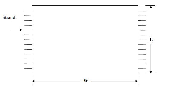
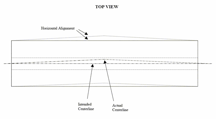
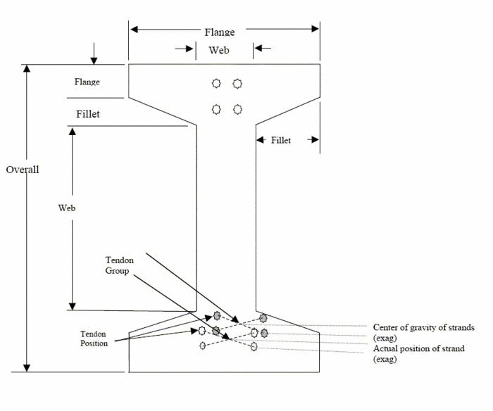
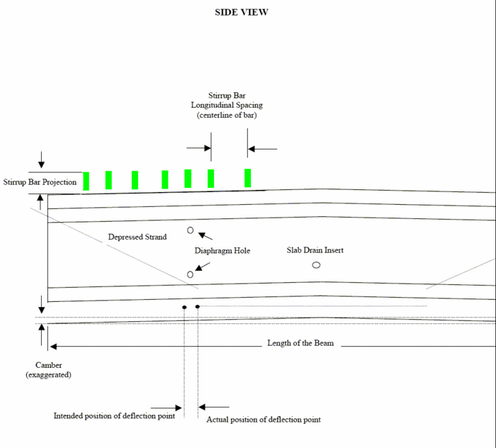
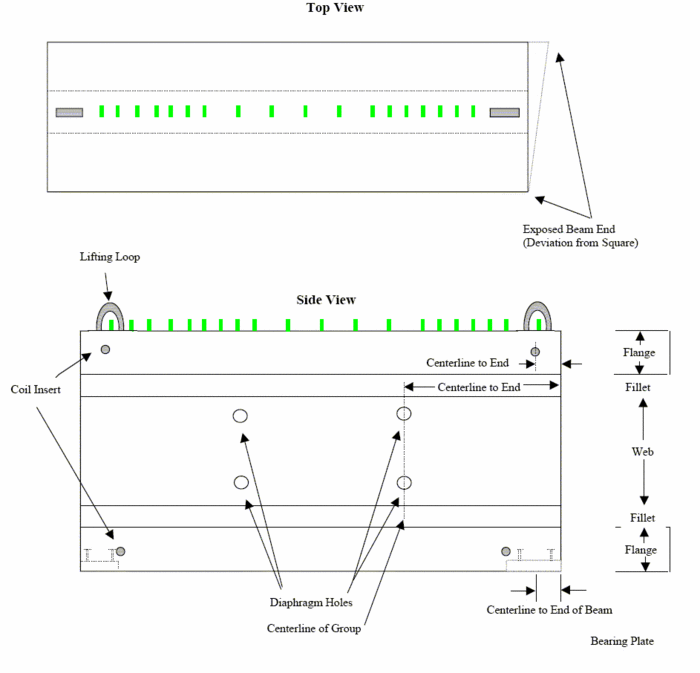
If definite tolerances are not specified in the contract, the tolerances shown in the applicable table of Sec 1029.7 shall be used by the inspector. If the members vary from these tolerances, the State Construction and Materials Engineer shall be consulted. Assistance in determining measurement of tolerance is provided in Fig. 1029.4.1, Fig. 1029.4.2, Fig. 1029.4.3, Fig. 1029.4.4, Fig. 1029.4.5 and Figure 1029.4.6.
1029.2.13.2 Marking
The inspector shall ensure that each member is identified with the date, manufacturer, identification number and load design when applicable. These markings may be indented on the member or painted thereon with waterproof paint. These markings shall be located as shown on the plans. If the location of the markings is not shown on the plans, they shall be located in such a manner that they will not be obvious or objectionable to the traveling public after the member has been placed in its final position. Accepted members are to be stamped with an "OK – MoDOT" by the inspector.
1029.2.13.3 Deck Panel Cracking
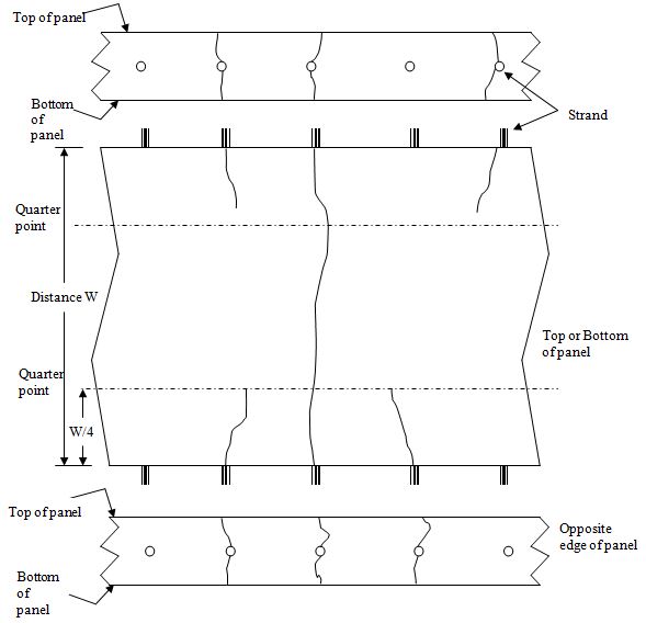
The inspector shall inspect the prestressed deck panel for cracking. Most cracking is unacceptable; however, certain cases of hairline cracks may be accepted. Hairline cracks are defined as very fine to nearly invisible, with no spalling of material along the crack, and may be more visible when the concrete is wet. Inspection shall be performed by visual examination without the addition of water to exaggerate the presence of the crack. Hairline cracks may be accepted, provided not more than one crack extends the entire span of the panel, the crack runs generally parallel to the strands, and there are not more than two cracks originating from any point. A maximum of three cracks may run from both strand edges of the panel toward the middle, with not more than one all the way from edge to edge, and any remaining cracks no further than the quarter points of the panel. Panels that are cracked as a result of obvious physical abuse, e.g. dropped or otherwise marred are not acceptable. Any questionable panels shall not be accepted until the Central Office has been consulted. Figure 1029.4.1 shows the worst-case panel that may be accepted.
1029.2.14 Handling, Storing and Transporting
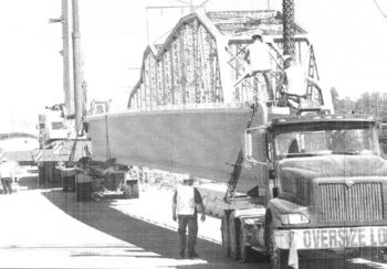
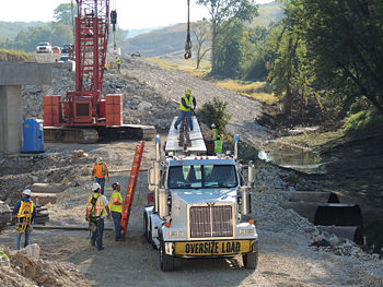
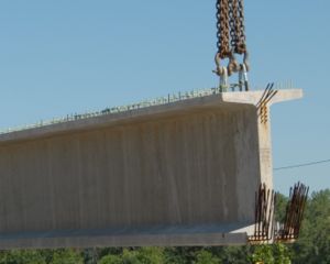
The handling and storage of prestressed members shall be in accordance with Sec 1029.6.13. In storage, I-beams should be fully supported across their width on battens that are not less than 4 in. (100 mm) wide. During transportation, the ends of I-beams should not extend a distance of more than the depth of the beam beyond the bolsters or other supports on the transporting vehicle. Deck beams should not extend more than 1 1/2 times their depth beyond the supports on the transporting vehicle. During storage, the supports shall maintain the members in essentially a level position without twisting. Stacking of the members in storage will be permitted only with the approval of the engineer. If such permission is granted, the supports of all members shall be in the same vertical planes and shall be of adequate thickness to prevent damage to the lifting devices.
1029.2.15 Bond Breaker
The application of a bond breaker to portions of the top flange is required for NU girders and spread beams. The inspector shall ensure the fabricator applies the bond breaker to these members in accordance with Sec 1029.6.17 and the approved shop drawings.
1029.2.16 Request for Acceptance of Incorrectly Fabricated or Damaged Members
The manufacturer or contractor shall initiate the request for acceptance of incorrectly fabricated or damaged members at the district office level. The manufacturer or contractor must include with their request, a detailed explanation of the problem and their proposed resolution, pictures of the member (if available), supporting calculations (as necessary) and shop drawings detailing the repair (as necessary). The district office will then forward the request to Materials, including any additional information they feel necessary and their recommendation if they have one. Materials will then evaluate the problem and the proposed resolution. If necessary, Materials will consult Bridge and supply them with all related documentation and information. Materials or Bridge may request additional information as needed. Bridge will perform an analysis and respond to Materials with their recommendation. Materials will then respond to the district office with a written statement of the Bridge’s (or Materials’) recommendation, and the district office will determine and make the final response to the manufacturer or contractor. There may be instances where Materials grants verbal approval of a repair and acceptance, but a written statement will always be issued to the district office and forwarded to the manufacturer or contractor.
1029.2.17 Approved Standard Repairs
There are approved standard repairs for certain errors or damages that may occur when fabricating, handling, transporting, or working near prestressed members. These approved standard repairs do not require consultation of Materials and can be found herein, however, such repairs will be noted on the shop drawings and the shop drawings will be resubmitted to Bridge.
1029.2.17.1 Incorrectly Located Coil Inserts
There may be instances where the coil inserts have been incorrectly located on the beam. The manufacturer or contractor will be allowed to patch the incorrect holes with an approved non-shrink grout. New holes may be drilled using approved methods, making sure that all steel reinforcement and strands are avoided and proper cover is provided. If the manufacturer or contractor is able to drill holes large enough to house a coil insert, the coil inserts may be epoxied into the holes using an approved epoxy and following the manufacturer’s recommendations. Alternately, if the manufacturer or contractor is only able to drill holes large enough to house a coil rod due to the proximity of embedded steel or strand, the coil rods may be epoxied directly into the holes using an approved epoxy and following the manufacturer’s recommendations. Short coil rods may be used and extended using a coupling device to accommodate placement of the beam in the field. If the coil rods require bending, they should be shop bent whenever possible.
1029.2.17.2 Incorrectly Located Diaphragm Holes
There may be instances where the diaphragm holes have been incorrectly located on the beam. The manufacturer or contractor will be allowed to patch the incorrect holes with an approved non-shrink grout. New holes may be drilled using approved methods, making sure that all steel reinforcement and strands are avoided and proper cover is provided.
1029.2.17.3 Correction of Horizontal Alignment (Sweep)
The following procedures shall be followed in the event of prestressed concrete I-Girders having developed sweep in excess of the allowable specification requirements of Sec 1029 Table 1. The procedures described in this subarticle apply only to a uniform sweep with single lateral curvature producing a maximum offest at the mid-point of the beam length. Sweep in prestressed girders shall be measured at the web mid-point utilizing a cotton or nylon string tied to the girder ends with sufficient tension. A conventional tape measure or a ruler may be used to measure the sweep. If dimensions in sweep are found to be out of the tolerance limits of Table 1, a MoDOT representative will notify the fabricator of deficient dimensions and will document the corrective procedures and acceptance/rejection of I-Girders using Form 1029-01.
- A. Girders with deflections that are less than two times the tolerances listed in Sec 1029 Table 1, may be corrected at the fabricator’s plant prior to shipping to the project site. Beams shipped must comply with Sec 1029 requirements.
- B. Girders that have deflections greater than two times the tolerances listed in Sec 1029 Table 1, will require the fabricator submit a repair request to the Construction and Materials Division or Bridge Division for approval.
- C. Bridge Division will predetermine the acceptable force allowed to correct deflections referenced in paragraph “B”.
- D. An I-Girder with a twisted upper flange or lower flange shall not be accepted.
- E. If approval is required, a written request shall be made to the MoDOT inspector at the plant. The MoDOT inspector will then forward the request to the Construction and Materials Division or Bridge Division for review and approval.
1029.2.18 Records
The plant inspector shall maintain a complete file of all data pertaining to the manufacture of the concrete units, either at the manufacturing plant or in the district office. Complete and accurate records of each manufacturing operation shall be kept in a field book. All pertinent data which in any way affects or influences the construction procedures or completed members including identification, camber and measurements required to determine acceptability for all members shall be recorded in the field book. Data shall be entered in the field book as soon as it is known. Field notes should not be copied but shall be kept exactly as they are originally recorded.
1029.3 Report (Records)
Materials shall be reported as shown in the corresponding sections of the Engineering Policy Guide. Prestressing strands and structural steel, if required, shall be reported through AWP. The record shall show all pertinent information regarding the material and a copy of the certification shall be retained in the district. The report is to indicate acceptance, qualified acceptance or rejection. Appropriate remarks as described in Reporting Test Results, are to be included in the report to clarify conditions of acceptance or rejection.
Distribution of the reports is to be as shown in the corresponding sections of the Engineering Policy Guide except that the copies normally forwarded to the Resident Engineer shall be furnished to the inspector at the precast manufacturing plant. The reports shall be marked "District General" and the name of the precast concrete manufacturer must be shown. The material is to be shown for use in "Precast Concrete Units." The plant inspector located at the concrete proportioning plant shall furnish a plant inspector's daily report in AWP for each day's pour identifying the units manufactured from that pour. The name of the manufacturer or set-up must be shown.
When precast concrete units are delivered to a given project, AWP samples shall be completed with distribution of reports as described in Reporting Test Results. Distribution of reports for materials purchased under a MoDOT purchase order is to be as described in EPG 1101 Materials Purchased by a Department Purchase Order.
1029.4 Figures
Figure 1029.4.1
Figure 1029.4.2
Figure 1029.4.3
Figure 1029.4.4
Figure 1029.4.5
Figure 1029.4.6
