751.35 Concrete Pile Cap Integral End Bents
751.35.1 General
751.35.1.1 Material Properties
| Concrete | ||
|---|---|---|
| Class B Concrete (Substructure) | = 3.0 ksi | |
| = 10 | ||
Class B-1 Concrete (Substructure) may also be used in special cases (See Project Manager). The following equations shall apply to both concrete classes:
Modulus of elasticity,
Where:
- f'c in ksi
- wc = unit weight of nonreinforced concrete = 0.145 kcf
- K1 = correction factor for source of aggregate
- = 1.0 unless determined by physical testing
Modulus of rupture,
- LRFD 5.4.2.6
Where:
- f'c is in ksi
| Reinforcing Steel | ||
|---|---|---|
| Minimum yield strength, | = 60.0 ksi | |
| Steel modulus of elasticity, | = 29000 ksi | |
751.35.2 Design
751.35.2.1 Limit States and Factors
In general, each component shall satisfy the following equation:
Where:
| = Total factored force effect | |
| = Force effect | |
| = Load modifier | |
| = Load factor | |
| = Resistance factor | |
| = Nominal resistance | |
| = Factored resistance |
Limit States
The following limit states shall be considered for abutment design:
- STRENGTH – I
- STRENGTH – III
- STRENGTH – IV
- STRENGTH – V
- SERVICE – I
- FATIGUE
- EXTREME EVENT - II
See LRFD Table 3.4.1-1 and LRFD 3.4.2 for Loads and Load Factors applied at each given limit state.
Resistance factors
- STRENGTH limit states, see LRFD 5.5.4.2 and LRFD 6.5.4.2
- For all other limit states, = 1.00
751.35.2.2 Loads
Dead Loads
Loads from beams, girders, etc. shall be applied as concentrated loads applied at the centerline of bearing. Loads from concrete slab spans shall be applied as uniformly distributed loads.
Live Loads
Loads from beams, girders, etc. shall be applied as concentrated loads applied at the centerline of bearing. Dynamic load allowance (impact) should be included for the design of the beam. No dynamic load allowance should be included for foundation design.
For wings with detached wing walls, no portion of the bridge live load shall be distributed to the detached wall. The detached wing wall shall be designed as a retaining wall. The weight of the barrier or railing on top of the wall shall be included in the dead load.
Collision
Collision shall be designed if abutments are located within a distance of 30.0 feet to the edge of roadway, or within a distance of 50.0 feet to the centerline of a railway track and conditions do not qualify for exemptions given in EPG 751.2.2.6.
751.35.2.3 General Design Assumptions
Beam
The beam shall be assumed continuous over supports at centerline of piles.
One half of the dead load of the approach slab shall be included in the beam design.
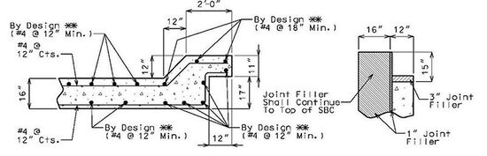
Wing
The standard horizontal reinforcement shown below was designed for soil pressure, EH, live load surcharge, LS and a railing collision force, CT for Extreme Limit State II Load Combination.

The minimum steel placed horizontally in wings shall be as shown in the figure below.

751.35.2.4 End Bent Analysis
The following steps shall be used to design integral end bents.
751.35.2.4.1 Beam Cap Design
Step 1 – Obtain loads from superstructure
The live load reactions (LL), dead load of structural components (DC), and dead load of future wearing surface (DW) will be needed to design the end bents. Strength I Load Combination will be used to design the reinforcement.
Step 2 – Design bearing pads or girder chairs
From the loads obtained in Step 1, design the bearing pads or girder chairs according to EPG 751.11.
Step 3 – Find beam cap width
The standard beam cap width will be 3’-0”. However, if the bearing pad size required exceeds the allowable edge distance, the beam cap width may be widened. The bearing pads shall be centered over the centerline of pile location, which is 15” away from the stream or crossing face of the cap.
Step 4 – Design longitudinal steel in beam cap
If the centerline of bearing is 12” or less on the centerline of piles, use 4 - #6 bars at the top and bottom of the beam cap. Otherwise, the ultimate moment used for designing the longitudinal steel shall be approximated by the following equation and figure. The loads shall be factored according to the Strength I Load Combination.
Where:
| = maximum interior girder reaction of factored superstructure loads, kips. | |
| = pile spacing, ft. | |
| = factored substructure loads equally distributed across the beam, k/ft. |

- Basic Assumption for Beam Analysis
A minimum of 4 - #6 Bars shall be used for the longitudinal steel in the beam cap. If more steel is required, increase bar size and keep the number of bars to 4. For example, use 4 - #7 bars instead of 5 - #6 bars.
The minimum reinforcement and bar spacing shall also be checked against the appropriate limits.
751.35.2.4.2 Pile Design
Follow Fig. 751.35.2.4.2 Integral Abutment Pile Design Flowchart and select applicable pile design method from following list:
- 1. Rigorous pile design procedure
- 2. Simple pile design procedure
- 3. Design pile in accordance with LRFD specification

751.35.2.4.2.1 Rigorous Pile Design Procedure
See Development Section, Structural Project Manager (SPM), or Structural Liaison Engineer (SLE), or 17-01-SEP-New Integral End Bent Pile Design Procedure.
751.35.2.4.2.2 Simple Pile Design Procedure
Use this procedure if bridge meets the length and skew limits tabulized in Fig. 751.35.2.4.2, Integral Abutment Pile Design Flowchart, bridge does not require a complete seismic analysis and where scour can be ignored.
Simple curved structures following similar length and skew limits are allowed. Complex thermal movements may require rigorous procedure.
Minimum pile embedment, See EPG 751.1.2.22 Types of Piling.
Rotate HP piles for skews over 45°, resulting in strong axis parallel to center line of beam cap.
Show pile prebore elevation on the plan where applicable in accordance with flowchart. Side friction in prebored areas shall be ignored.
See EPG 751.36.5.7.1 Integral End Bent Simple Pile Design for typical pile design values.
751.35.2.5 Beam Reinforcement Special Cases
SPECIAL CASE I
If centerline bearing is 12" or less on either side of centerline piles, for all piles (as shown below), use 4-#6 top and bottom and #4 at 12" cts. (stirrups), regardless of pile size.

SPECIAL CASE II
When beam reinforcement is to be designed assuming piles to take equal force, design for negative moment in the beam over the interior piles.

751.35.3 Dimensions
751.35.3.1 Front Sheet
| Notes: | The following are details and dimensions for the Plan view on the Front Sheets. |
| Details for unsymmetrical roadways will require dimensions tying Centerline Lane to Centerline Structure. |

751.35.3.2 Wing Brace
The wing brace dimensions will only vary on the wing with obtuse angle. Wing brace dimensions shown are minimum dimensions. The wing brace with the acute angle will always be 18" minimum.

|
| Skews 0° thru 45° |
|---|

|
| Skews 45°00'01" thru 55° |

|
| Skews 55°00'01" and Over |
| Note: | Left advance shown, right advance similar. |
751.35.3.3 Prestressed Girder End Bent

- (1) See EPG 751.12 Barriers, Railings, Curbs and Fences for barrier or railing details.
- (2) Keep 1 1/2" minimum clear cover for reinforcement between approach notch and girder. Increase beam width (1" increments) to get the 1 1/2" clear cover if necessary.
- (3) Use 1” plus half of bearing pad length when bearing pads are used. Use 3 ½” minimum for NU Standard Girders and 5” minimum for MoDOT Standard Girders when girder chairs are used.
- (4) 12" minimum at gutter line at end of slab.
- (5) All concrete in the end bent above top of beam and below top of slab shall be Class B-2.
- (6) Provide a minimum of 8" clearance from outside edge of pile to face of beam. For pile greater than 14” wide (diameter), shifting pile centerline towards fill face is preferred based on structural considerations (eccentric load to pile). Otherwise, increase beam width (1” increments) toward front face in order to meet 8” minimum clearance.
- Example:
- Pile size = 16”
- Option I (preferred): Shift pile centerline 1” toward fill face and consider eccentric load to the pile.
- Minimum beam width = 20”+16”=3’-0”
- Option II: Increase beam width 1” toward front face.
- Minimum beam width = 21”+16”=3’-1”
- (7) See Design Layout for maximum spill slope.


| Note: | Neoprene bearing pads are to be used on integral bents (prestressed structures) if pad size and beam clearance permit; otherwise, use girder chairs. See EPG 751.11.3.6 Girder/Beam Chairs for additional girder chair details. |
| Squared beam steps are shown. Steps may be skewed to facilitate placement of U1 and V1 stirrup bars. See EPG 751.35.4 Reinforcement for details. | |
| * | 18" minimum, 2'-0" maximum; provide a minimum of 8" clearance from outside edge of pile to outside face of beam. |
751.35.3.4 Steel Girder or Beam End Bent

- (1) See EPG 751.12 Barriers, Railings, Curbs and Fences for barrier or railing details.
- (2) Keep 1 1/2" minimum clear cover for reinforcement between approach notch and girder. Increase abutment beam width (1" increments) to get the 1 1/2" clear cover if necessary.
- (3) Use 1" plus half of bearing pad length when bearing pads are used. Use 3" minimum when girder chairs are used.
- (4) 12" minimum at gutter line at end of slab.
- (5) All concrete in the end bent above top of beam and below top of slab shall be Class B-2.
- (6) Provide a minimum of 8" clearance from outside edge of pile to face of beam. For pile greater than 14” wide (diameter), shifting pile centerline toward fill face is preferred based on structural considerations (eccentric load to pile). Otherwise, increase beam width (1” increments) toward front face in order to meet 8” minimum clearance.
- Example:
- Pile size = 16”
- Option I (preferred): Shift pile centerline 1” toward fill face and consider eccentric load to the pile.
- Minimum beam width = 20”+16”=3’-0”
- Option II: Increase beam width 1” toward front face.
- Minimum beam width = 21”+16”=3’-1”
- (7) See Design Layout for maximum spill slope.


| Note: | Neoprene bearing pads are to be used on integral bents (steel structures) if pad size and beam clearance permit; otherwise, use girder chairs. See EPG 751.11.3.6 Girder/Beam Chairs for additional girder chair details. |
| Squared beam steps are shown. Steps may be skewed to facilitate placement of U1 and V1 stirrup bars See EPG 751.35.4 Reinforcement for details. | |
| * | 18" minimum, 2'-0" maximum; provide a minimum of 8" clearance from outside edge of pile to outside face of beam. |
| ** | 3" minimum clearance between sole plate and keyed construction joint (typical) |
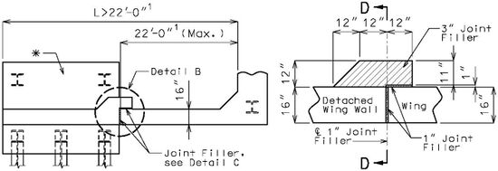
751.35.3.5 Wing and Detached Wing Walls
For seismic design category A: When wing length, L, is greater than 22’-0”, use maximum 22’-0” integral abutment wing wall combined with detached wing wall.
Standard wing reinforcement is developed assuming a pinned connection at the bottom (tip) of wing. This assumption is applicable for cases where the passive pressure from the fill slope can be counted on to partially resist the active forces from the backfill. In a seismic event the forces on the wings are developed by the wings moving into the soil backfill and the fill slope resistance is less reliable. For seismic forces wings shall be designed assuming there is no lateral restraint at the bottom of the wing. The reduced restraint conditions require a more practical limit for the wing length.


-
 Section A-A
 -
 Detail B


| Note: | |
| * | Detached wing wall shown is for illustration purpose only. Design detached wing wall as a retaining wall (EPG 751.24). |
| ** | Use retaining wall design. |
| 1 For seismic design category B, C and D only: The wing length shall not be greater than 17 feet. When a detached wing wall is required the integral abutment wing length shall not exceed 17 feet. | |
| Report Pile Cut-off Elevation and Minimum Galvanized Penetration (Elev.) (See EPG 751.50 Standard Detailing Note E2, (Foundation Data Table). |
751.35.4 Reinforcement
For epoxy coated reinforcement requirements, see EPG 751.5.9.2.2 Epoxy Coated Reinforcement Requirements.
751.35.4.1 Wide Flange Beams & Plate Girders

| ||||
| Part Section Near End Bent | ||||
 |

| |||
| Section A-A | Section B-B | Section C-C | Section D-D | |
 |

| |||
| Alternate Section A-A | Alternate Section B-B | Alternate Section C-C | Alternate Section D-D | |
| Detailing Guidance: | ||||
| Green items are guidance only and shall not be shown plans. | ||||
| Place all U bars and V pairs parallel to centerline roadway. | ||||
| Keep 1 1/2" clearance between the piles and the U1 or U2 bars. | ||||
| Keep 1 1/2" clearance between the beams or girders and the U1 or V1 bars. | ||||
| Keep 1 1/2" clearance between the angles of girder chairs and the U2 or U3 bars. | ||||
| Replace U1 bars with U3 bars at piles under beams or girders. | ||||
| Replace U1 bars with V1 bars at piles between beams or girders. | ||||
| When dimension “A” is required to be greater than 15” to clear piles by 1 ½”, typical when HP14 and CIP14 or larger diameter piles are used, add intermediate longitudinal bar(s) between piles. The spacing between intermediate bar(s) and full length bars shall not be greater than required by crack control provisions. Ends of intermediate bar(s) shall be hooked. | ||||
| See EPG 751.50 G1 Concrete Bents for appropriate notes to be placed with details. | ||||
| (1) #6-U bar ( | ||||
| (2) U4 bars ( stirrup hooks may be required for U4 bars ( minus 1” clear. | ||||
| (3) U1 bars ( lap length requirement across length of diaphragm. For shallow beams stirrup hooks may be required for U1 bars ( bars ( | ||||
| (4) Stirrups shall clear step by 1 1/2" minimum, if not lengthen step or skew step. | ||||
| (5) #6-V bars at no more than 9” centers at the end of girders or beams. | ||||
| (6) #5-U bars (15”H x 24”V) @ about 12" centers placed parallel to centerline roadway. When approach slab haunch is expected to be greater than 18” at the roadway crown at the end of slab, slope the approach slab notch providing 12” of constant approach slab haunch or with SPM or SLE approval greater than 18” approach slab haunch may be used but increase vertical leg length of #5-U bars to ensure 12” minimum embedment. For shallow beams where 12” embedment is not available adjust length of vertical leg and extend to top of beam minus 1” clear. | ||||
| (7) With SPM or SLE approval a 24” splice may be used in combination with specifying 2” cover to U bars and V bars if doing so avoids the need for using hooked bars. | ||||
| (8) See tables for 1 1/16" round hole spacing for #6-H bars. | ||||
| (9) Same number of bars as 1 1/16" round holes in beam or girder. | ||||
| (10) Add intermediate longitudinal bar(s) when required for spacing. Keep 3” minimum clearance between the pile and intermediate longitudinal bar(s). | ||||
751.35.4.2 Prestressed I-Girders, Bulb-Tee Girders and NU-Girders

| ||||
| Part Section Near End Bent | ||||
 |

| |||
| Section A-A | Section B-B | Section C-C | Section D-D | |
 |

| |||
| Alternate Section A-A | Alternate Section B-B | Alternate Section C-C | Alternate Section D-D | |
| Detailing Guidance: | ||||
| Green items are guidance only and shall not be shown plans. | ||||
| Place all U bars and V pairs parallel to centerline roadway. | ||||
| Keep 1 1/2" clearance between the piles and the U1 or U2 bars. | ||||
| Keep 1 1/2" clearance between the beams or girders and the U1 or V1 bars. | ||||
| Keep 1 1/2" clearance between the angles of girder chairs and the U2 or U3 bars. | ||||
| Replace U1 bars with U3 bars at piles under beams or girders. | ||||
| Replace U1 bars with V1 bars at piles between beams or girders. | ||||
| When dimension “A” is required to be greater than 15” to clear piles by 1 ½”, typical when HP14 and CIP14 or larger diameter piles are used, add intermediate longitudinal bar(s) between piles. The spacing between intermediate bar(s) and full length bars shall not be greater than required by crack control provisions. Ends of intermediate bar(s) shall be hooked. | ||||
| See EPG 751.50 G1 Concrete Bents for appropriate notes to be placed with details. | ||||
| (1) #6-U bar ( | ||||
| (2) U4 bars ( stirrup hooks may be required for U4 bars ( minus 1” clear. | ||||
| (3) U1 bars ( lap length requirement across length of diaphragm. For shallow beams stirrup hooks may be required for U1 bars ( bars ( | ||||
| (4) Stirrups shall clear step by 1 1/2" minimum, if not lengthen step or skew step. | ||||
| (5) #6-V bars at no more than 9” centers at the end of girders or beams. | ||||
| (6) #5-U bars (15”H x 24”V) @ about 12" centers placed parallel to centerline roadway. When approach slab haunch is expected to be greater than 18” at the roadway crown at the end of slab, slope the approach slab notch providing 12” of constant approach slab haunch or with SPM or SLE approval greater than 18” approach slab haunch may be used but increase vertical leg length of #5-U bars to ensure 12” minimum embedment. For shallow beams where 12” embedment is not available adjust length of vertical leg and extend to top of beam minus 1” clear. | ||||
| (7) With SPM or SLE approval a 24” splice may be used in combination with specifying 2” cover to U bars and V bars if doing so avoids the need for using hooked bars. | ||||
| (8) Add intermediate longitudinal bar(s) when required for spacing. Keep 3” minimum clearance between the pile and intermediate longitudinal bar(s). | ||||
751.35.4.3 Wing Reinforcement
 |

|
| Elevation Of Wing | Typical Section Thru Wing |

| |
| Part Plan (Squared) | |

| |
| Part Plan (Skewed) | |
| Detailing Guidance: | |
| Green items are guidance only and shall not be shown plans. | |
| Bar marks shown are for these details only. Vary as needed. | |
| K bars not shown in the Elevation of Wing for clarity. For details of K bars, see EPG 751.12.1.4.3 End of Barrier Reinforcement for Type B barrier and EPG 751.12.1.3.3 End of Barrier Reinforcement for Type D and H barriers. | |
| See EPG 751.35.3.3 for chamfer detail. | |
| (a) Use dimension that provides a minimum of 3" center to center spacing between #6 bars placed horizontally and #8 bars placed with grade. See SPM or SLE if spacing at one end exceeds 8 inches due to grade. | |
| (b) Use construction joint on steel structures only. | |
| (c) 6 3/8” min and 11 3/8” max. If unable to get dimension to fall within this range using 8-inch centers, then use 6 3/8” and use “@ abt. 8” cts.” | |
| (d) Use 66.5” for obtuse corner of bents skewed 55 degrees or greater. | |
| (e) Use 54.5” for obtuse corner of bents skewed 55 degrees or greater. | |
| (f) See 751.50_Standard_Detailing_Notes#G1._Concrete_Bents EPG 751.50 G1 Concrete Bents for note (G1.7) required for the #6-F bars. | |
| (g) Use 90 degree standard hook in seismic areas. | |
| (h) Adjust as needed if girder web prevents proper placement of bars (i.e., if ALL bars would need to be bent in field according to note G1.7). Rotate leg 90° for box beams. If necessary, the leg may be rotated 90° for other prestressed girder shapes. | |
751.35.4.4 Skewed Bents
Prestressed I-girders shown in the following details, steel structures are similar.
The sections thru integral end bents previously shown shall be adjusted for skew as shown.

751.35.4.5 Coil Inserts and Tie Rods
Threaded rods (coil tie rods) installed in coil inserts (coil ties) that are cast into the ends of prestressed girders and beams are believed to provide some aid in resisting positive moment forces.
Coil ties and rods shall be detailed on the plan sheets for prestressed girders and beams.
| Bridge Standard Drawings |
| Prestressed I-Girders |
| Prestressed Box Beams |
Coil ties and coil tie rods shall be detailed on the plan sheets for integral end bents as shown below. Girders and beams with coil ties and rods are available as standard cells under the concrete diaphragm tasks in MicroStation.

| Detailing Guidance: |
| Green items are guidance and shall not be shown on plans. |
| Details shows I girders but are applicable for all girder and beams based on coil tie locations shown for closed diaphragms on the bridge standard drawings for prestressed girders and beams. |
| (a) “Two” not required for bulb-tee and NU girders. |
751.35.5 Details
751.35.5.1 Reinforcing Holes

|

|
| Section at End of Beam | Section A-A |
|---|
| WF Beam Depth | Stud Spacing | A | Reinforcing Hole Spacing |
|---|---|---|---|
| 21" | 2 spa, @ 4 1/2" | 4" | 2 equal spaces |
| 24" | 2 spa. @ 6" | 4" | 2 equal spaces |
| 27" | 2 spa. @ 7 1/2" | 4 1/2" | 2 equal spaces |
| 30" | 3 spa. @ 6" | 4 1/2" | 3 equal spaces |
| 33" | 3 spa. @ 7" | 4 1/2" | 3 equal spaces |
| 36" | 4 spa. @ 6" | 4 1/2" | 3 equal spaces |

| |
| Section at End of Girder | |
|---|---|
| Note: | Bearing stiffeners are to be designed for DC (no SBC or FWS) and 50 psf construction load. (No web studs are required since bearing stiffener is provided). |
| *** | 1 1/16"ø holes for skews thru 20°. For skews > 20°, use slotted hole = 1 1/16" + 2(Web thickness)x(tan of the skew angle) |
| PL Girder Depth | A | Reinforcing Hole Spacing |
|---|---|---|
| 39" | 3 1/2" | 4 equal spaces |
| 42" | 3 1/2" | 5 equal spaces |
| 48" | 4" | 5 equal spaces |
| 54" | 4 1/2" | 6 equal spaces |
| 60" | 4" | 8 equal spaces |
751.35.5.2 Vertical Drains
| Bridge Standard Drawings |
| Vertical Drain at End Bents |