Category:239 Construction Inspection Guidelines for Final Plans

A set of final plans is a record as well as a graphic representation of the completed project. The quantities and other information shown on the final plans and in the supporting documents are used by Construction and Materials to determine the final payment due contractors for the work performed and to furnish other MoDOT divisions with valuable information. Since the final plans are burned onto a CD, it is imperative the plans are neat with changes being made in MicroStation.
If preparation and submission of final plans are delayed, contractor's final payment is delayed along with MoDOT's reimbursement from the FHWA. Completed final plans should reach the district office within eight weeks after final inspection or within six weeks if the project is one that both costs less than $1,000,000.00 and has fewer than 40 bid items (see Sec 105.10.7). If the Resident Engineer cannot complete final plans in this allotted time, a written explanation must be sent to the contractor notifying the contractor of this delay. A copy of this letter should be sent to the district office and Central Office estimating the date plans will be submitted. The districts are, in turn, allotted two additional weeks for checking plans. Once all the required documentation is received (Final Acceptance, Sec. 105.15.2), the district should immediately send the final plans to Central Office. A sample project timeline is a reference.
Central Office should be notified as soon as accepted for maintenance has occurred and then when final inspection has been made. These could possibly be the same date or may be different dates depending on the job.
239.1 Preparation
Final plans should be prepared carefully, accurately and in sufficient detail so that a person who has not seen the actual construction of the project may obtain a clear picture of the work and be able to check the quantities shown on the plans without requiring additional information. While the final plans are a record of the completed project, it will not be necessary to revise notes to read in the past tense. All sheets should be reviewed and heavied-in in such a way that they will ensure good reproduction. Ink or mylar pencils should be used for making changes if not done in Microstation. Pen plotted original drawings must use black ink. Completed plans should present a neat, uniform and legible appearance. All erasures must be neat, no correction fluid or labels are allowed. The 2A sheet will include the following note:
“These plans accurately depict the configuration and locations of the roadway and all appurtenance features, including modifications designated or authorized by the engineer of record.”
The note will be signed and dated by the Resident Engineer. Since final plans are now scanned onto a CD, it is absolutely necessary they be of good quality. Final plans submitted with sheets torn, crumpled, burned or defaced will be returned for correction. If plans are produced using Microstation, please print them out on 11x17 paper if possible when submitting. There is also a disclaimer stamp in Microstation that can be adjusted to fit the plan sheet.
239.2 Submittal
The RE should send the final plans to the district as soon as possible after checking. This submittal shall include the estimate item detail report from AWP and all other final papers pertinent to this project.
The district should send the plans, to Construction and Materials Division with a letter of transmittal. The letter of transmittal should list the material being sent and include the following recommendations, if applicable.
A recommendation should be submitted with the final plans concerning the assessment of liquidated damages if the project has gone into overtime. State whether the prime contractor has been informed in writing of the deduction to be made. The contractor’s objection, if any, should be included.
Prior to release of final payment on Federal-Aid projects containing Disadvantaged Business Enterprise (DBE) provisions, the contractor is required to file a list showing the DBE's used and the work performed. The list is to show the actual dollar amount paid to each DBE. The Resident Engineer should provide a recommendation as to the contractor's compliance with the required participation.
239.3 Title Sheet
The title sheet shows project location, all equations and limiting stations and the actual constructed length of the project in miles. In the upper right hand corner the route, district, state, job number, project number, contract ID and county will be given. Normally, the title sheet will not require any significant changes. Check to see that all lettering or changes are heavied-in to ensure good reproduction and the word “Proposed” is removed.
239.4 Typical Sections
Typical section sheets are to be included in the final plans and are to reflect the as-built sections. Worn or soiled sheets are to be replaced before submitting.
239.5 2A Sheets
The 2A Sheet and the estimate item detail provide a summary of quantities included in a contract for which payment is to be allowed. 2A sheets will no longer be included in contract plans awarded after the summer of 2007, but still should be included in final “as built” plans.
The original quantities shall be changed to reflect the as-built quantities. These sheets must be created using Microstation. Machines must have both Microstation and AWP installed on it. Under the “Construction” pulldown in MicroStation and choose the “2a Sheet Program – Construction” option. If a Alert dialog box comes up about AASHTOWARE Project (AWP), click “OK”. Type in the first two numbers of the contract ID for the search string. Then highlight the contract wanted. Select the printer and paper size.
Those items having alternate numbers in the contract should be corrected to show the proper number used in the project. When options are given, correct as necessary to show only the type material or option used. Example: Crushed stone (A) or Gravel (B), remove the item that was not used.
The 2A Sheets must be created electronically in Microstation. This will automatically add applicable contingent items. This is done after the last change order has been checked and entered in AWP. This method to create 2A plot sheets can be edited in Microstation. To edit, first create the 2A sheet using Microstation. This creates a file in Microstation under t:\deproj\construction2A. Open the desired and start making changes. Once the 2A sheet has been created, the same sheet cannot be created again without first deleting the file it created in Microstation. Do this by going into Windows Explorer and going to t:\deproj\construction2A. Any 2A sheet created will be listed here and can be deleted here. After deleting the file, a new 2A sheet can be created.
The 2A Sheet shall identify who prepared and checked the tabulation as “Project Accepted”, “Prepared By”, “Checked By”, “Reviewed By (Resident Engineer)”, “District Office” and “Central Office” as well as provide the substantial compliance certification.
239.6 2B Sheet
Notes and items that are no longer appropriate should be deleted. All quantities should be corrected to show the as-built quantities. Do not remove any items from the 2B sheet. If the item has been underrun completely, enter zero (0) under that item total. Notes in the “Remarks” column should show when field measurement is made. All items that are tabulated on the 2B Sheet by location should be independently crosschecked against the plan profile sheets to determine whether the listed locations agree. If additional blank 2B Sheet forms are needed, created them using Microstation. Contingent items need to be added to the 2B sheets.
239.7 Plan Profile Sheets
Notes on the plan sheets pertaining to construction items may generally be used as listed by correcting to reflect final quantities. Remove all information and data not pertinent to as-built construction between right of way lines, with the exception of all land lines. All removals listed must be taken off the final sheets. Any excavation shown on these sheets should reflect the final amounts for that balance. All utility adjustment work, whether by permit or agreement, is to be inspected by the district and the location recorded on the final plans of the project.
239.8 Reference Points Sheet
Include reference points sheets in final plans making any correction as necessary.
239.9 Special Sheets
Special sheets may be used to show details that would be too extensive or confusing to show on plan sheets. Complex projects require the use of special sheets to show properly such items as utility adjustment work, sewer lines, interchange layouts, ramp grades, etc.
239.10 AWP Plans
Submission of final plans includes complete documentation in AWP plus any bound field diaries and pay quantity books used to accumulate AWP data. When circumstances allow, all data will be entered directly into AWP because AWP is the primary repository of project data. If bound field diaries or pay quantity books must be used, the information in those bound books will be exactly duplicated in AWP as soon as practical and to the extent possible.
239.10.1 Pay Quantity (DWR) Entries
When submitting AWP final plans the following changes shall be made in recording work items on the DWR.
All locations and remarks necessary to adequately describe a pay item shall be entered in the location bar of the DWR Work Items tab. A total of forty characters are available in this area. Include “from” and “to” values for Station, Offset and Distanced, when applicable. Sufficient detail regarding the location of the installation should be provided. Any other pertinent information that inspectors may need to collaborate their daily activities shall also be entered in this location.
When multiple locations are installed or paid on the same day, a separate location sequence number “Loc Seq Nbr” detailing each installation shall be entered. Combining multiple installations on one entry is unacceptable. Please refer to Daily Work Reports for detailed information regarding this issue. If these procedures are adhered to, final plans may be submitted using AWP documentation.
239.10.2 Guidelines
Documentation guidelines outlined above (DWR) shall be followed.
The “List of Reported Quantities” (Cognos report) serves as the final pay quantity report. This report details each individual installation for all line items included with any project, and shall be submitted. This report takes place of the books.
Estimate Item Detail serves as the final estimate and shall have the appropriate check marks showing the RE has checked the estimate against the “List of Reported Quantities” report.
Any bound field books containing survey/layout information and field measurements shall be submitted and indexed. The above documents are in addition to those items required for conventional final plans submittal.
239.11 Culvert Sections
Changes in excavation may be computed as deductions or addition to plan unless relocation was necessary. Check Standard Specifications carefully for Class 3 pay limits.
239.12 Bridge Sheets
The Resident Engineer will be furnished drawings of bridge design plan sheets. The drawings are to be used for recording accurate and complete as-built data for each bridge structure. When options such as alternate slabs, joints, etc. are given, remove all but the one actually used. All revisions and additions should be in Microstation. The Resident Engineer should use extreme care in the preparation of final plans to ensure that all pertinent information relative to the finished structure is fully and accurately shown. Legibility and neatness cannot be over emphasized since the finals may need to be reproduced at different times in the future.
In the Plan of the Structure on Sheet 1 of the bridge plans, any construction changes made in sizes of the footing should be shown. In pile bents it is necessary to show the spacing of the piles in each bent only when the distance between piles varies from plan by more than the specified tolerance. Actual lengths or ranges of lengths of piling should be shown in the table on the first sheet of the bridge plans, where estimated lengths are given. Unusual conditions should be clarified by notes or sketches to assure a complete and accurate record of as-built conditions. Any other changes shown on the detail sheets of the substructure plans should also be shown, if possible, in the General Elevation and Plan on Sheet No. 1. All revisions in reinforcement are to be shown in the bill of reinforcing steel. The Estimated Quantities tabulation should be changed to show actual final quantities.

Construction changes for each substructure unit are to be shown on the detail sheets. Where major changes occur in several substructure units covered by one original detail, additional drawings of the details involved should be created. This will provide a separate detail for each unit, on which correct dimensions may be shown. A table may be used, if only dimensions and elevations are involved, by substituting a letter for each dimension in the detail and listing the constructed dimensions in an appropriate column of the table. If the changes made affect only a small portion of the details and there is sufficient space available, detail any necessary additional sketches on the tracings that showed the original multiple-dimensioned details. If these instructions are carefully followed, it will seldom be necessary to prepare additional sketches on cross-section sheets.
 |
 |
 |
 |
239.12.1 M.S.E Wall Systems
Make sure to check the type of wall system used. Change the estimated quantities table to reflect the final quantities.
239.12.2 Final Quantity Computations Sheets
Final bridge quantities computations are to be prepared on standard size (8½ x 11) computation paper using the details as shown on the final plans for reference. If additional detailed sketches are needed to clarify computations, they should be made in pencil on the computation sheets. See Tables 239.12.2.1 and 239.12.2.2 for samples of preparing the computations. Test hole information should be shown on the bridge excavation computation sheet with the appropriate footing.
Table 239.12.2.1 Final Bridge Excavation Quantities Computation Example
| Project STP-BRF-60-1(11) | Sheet 1 of 22 | ||||
| Brg. At Sta. 1768+90 | Newton County | ||||
| Brg. No. A-4894 | Computed by: J. Eckhart | ||||
| - | Checked: F.C. Perch 4-30-03 | ||||
| SUMMARY – BRIDGE EXCAVATION – FINAL COMPUTATIONS | |||||
|---|---|---|---|---|---|
| - | Cl. 1 | Cl. 1 + 25% | Cl. 2 | Cl. 2 + 50% | |
| - | Cu. Ft. | Cu. Ft. | Cu. Ft. | Cu. Ft. | |
| Footing Bt. 1 | 1547.87 | 1430.25 | |||
| (4 – 6 ft. Test Holes) | |||||
| Lt. Footing Bt. #2 | 630.00 | 1350.00 | 1350.00 | ||
| Rt. Footing Bt. #2 | 322.20 | 1123.80 | 1350.00 | ||
| Lt. Footing Bt. #3 | 263.25 | 2705.62 | 589.88 | ||
| R. Footing Bt. #3 | 282.50 | 2047.50 | 1072.50 | ||
| Lt. Footing Bt. #4 | 414.00 | 900.00 | |||
| R. Footing Bt. #4 | 288.00 | 900.00 | |||
| Lt. Footing Bt. #5 | 414.00 | 900.00 | |||
| Rt. Footing Bt. #5 | 504.00 | 900.00 | |||
| Lt. Footing Bt. #6 | 396.00 | 900.00 | |||
| Rt. Footing Bt. #6 | 378.00 | 900.00 | |||
| Lt. Footing Bt. #7 | 1224.00 | 1350.00 | |||
| Rt. Footing Bt. #7 | 1224.00 | ||||
| Total | 5449.82 | 1430.25 | 15074.92 | 5712.38 | |
| 5449.82 ÷ 27 = 201.85 Use 202.0 Cu. Yds. Cl. 1 Exc. | |||||
| 1430.25 ÷ 27 = 52.97 Use 53 Cu. Yds. Cl. 1 Exc. + 25% | |||||
| 15074.92 ÷ 27 = 558.33 Use 558.5 Cu. Yds. Cl. 2 Exc. | |||||
| 5712.38 ÷ 27 = 211.57(558.33) Use 211.5 Cu. Yds. Cl. 2 Exc. + 50% | |||||
Table 239.12.2.2 Final Bridge Excavation Quantities Computation Example
| Project STP-BRF-60-1(11) | Sheet 22 of 22 | |||
| Brg. At Sta. 1768+90 | Newton County | |||
| Brg. No. A-4894 | Computed by: J. Eckhart | |||
| - | Checked: F.C. Perch 4-30-03 | |||
| FINAL COMPUTATIONS - BRIDGE EXCAVATION | ||||
|---|---|---|---|---|
| - | - | Cl. 1 | Cl. 2 | Cl. 2 + 50% |
| - | - | Cu. Ft | Cu. Ft. | Cu. Ft. |
| Intermediate Bent No. 7 Datum | 1086.0 | |||
| Lt. Ftg. Plan Elev. | 1078.0 | |||
| Lt. Ftg. Avg. Gr. Elev. | 1084.8 | |||
| Lt. Ftg. Bot. Ftg. Elev. | 1078.0 | |||
| *Lt. Ftg. Exc. Elev. | 1068.0 | |||
| 12.0 15.0 × 6.8 × = | 1224.00 | |||
| *9.0 15.0 × 10.0 × = | 1350.00 | |||
| Rt. Ftg. Plan Elev. | 1078.0 | |||
| Rt. Ftg. Avg. Gr. Elev. | 1084.8 | |||
| Rt. Ftg. Bot. Ftg. Elev. | 1078.0 | |||
| 12.0 15.0 × 6.8 × = | 1224.00 | |||
| *Additional Exc. To Remove Rock & Boulders To Drive Piling | ||||
| Auth. Cl. 2 + 50%; Exc. Limits: Ftg. Size + 18 in. on battered pile sides | ||||
239.13 Standard Plans Index
It is not necessary to include Standard Drawings in the final plans.
239.14 Roadway Cross-sections
If errors are found in the original computations or if a change in grade or typical section is authorized, the volume of excavation within the limits of the balance or area affected must be measured and/or recomputed. This may be done by plotting sections to show the increase or decrease or by computations of the difference. Cross-sections for computations of rock excavation, excavation shown on the plans as estimated quantities and borrow excavation must be prepared and submitted with the final plans unless the contract specifically makes other provisions.
When it is necessary to plot earthwork cross-sections, they should be plotted on standard 22 in. x 36 in. or 22 in. x 34 in. sheets. The scale generally used is one inch equals five feet, both vertically and horizontally. A scale of one inch equals ten feet may be used when the 1:5 scale won't fit on a standard sheet of cross-section paper. The plotting should start at the bottom of the sheet and proceed upward. If the width of the cross-section is so that two columns of cross-sections can be plotted with the 36 in. dimension of the paper placed horizontally, the plotting should start in the lower right corner and proceed to the top of the sheet and then continue in a second column from the bottom of the sheet at the left. If the width of the cross-section is so that it covers more than one-half of the 36 in. width, only one column of cross-sections should be plotted to avoid crowding and overlapping.
The original cross-sections should be plotted in pencil, checked and then inked. When using a pen plotter, only black ink is acceptable. The station number should be placed, in ink, at the right on a line with the end of the section. The centerline elevation should be shown in ink on a 45° slope above and to the right of the centerline. If the contract plans contain computer sheets instead of cross-sections, the district design department will furnish the original elevations obtained by personnel of that division. Final cross-sections are plotted in pencil superimposed on the original sections. The final centerline elevation should be shown vertically in pencil along the centerline above the section. Lines of demarcation for the various classes of excavation, the extent of any undergrading or backfill, and the limits for compaction must be indicated when applicable to the cross-section. On sheets showing rock sections, all authorized pay limits should be shown, including allowable overbreak and undergrading lines. If payment is authorized beyond typical or staked slopes, be sure to show proper notes explaining the authorization.
The area, in square feet, for each of the above items is to be planimetered or computed, and listed on the right under the station number. The volume for each item should be computed and the resulting quantities listed between the cross-sections. The excavation volumes should be placed to the left of the centerline, the compaction volumes on the centerline, and the embankment volumes to the right of the centerline.
Balance Points. All balance points should be shown on the profile portion of the plan-profile sheets. The total volumes for the various classifications of excavation should be listed at about the center of the balance in the same manner as shown on the design plans.
When changes are made, the affected balances should be shown in detail on the cross-section sheets. All balance points in such areas should be shown on the cross-section sheets along with a listing of the total volumes for the various classifications of excavation in the balance. All cross-sections pertaining to the balance in any way should be included with the roadway cross-sections. When a borrow pit is involved and the borrow is split among several balances, the borrow cross-sections should be included with the other sections for the first balance involved.
The balance point information may follow the example in EPG 239.14.1 Plan Quantity Basis when the basis of measurement is plan quantities. If a complete recomputation of quantities is necessary, the balance point information should summarize each classification of excavation as shown in EPG 239.14.1.1.
239.14.1 Plan Quantity Basis
Table 239.14.1 is a sample method of listing quantities for a balance in which Class C Excavation occurs, when payment for roadway and drainage excavation is to be made on the basis of plan quantities. If Class C Excavation is encountered at an elevation different from that shown on the contract plans, it will be necessary to adjust the quantities of Class A and Class C excavation by recomputation as provided in Sec. 203.6.2.5 of the Standard Specifications. Either method (a) or method (b) may be used as judgment dictates. Method (b) is illustrated in the following example. Where the elevation of the surface of Class C excavation differs greatly from that shown on the plans method (a) may be more desirable because of slope changes, which can significantly affect total volume of excavation. Per Sec 203.2.5.3 MoDOT no longer pays for Class C overbreak.
Table 239.14.1 Balance Point Example with Class C Excavation based on Plan Quantities
| Balance Point Station 125+50 | ||
|---|---|---|
| (1) | Plan Class A Excavation | 4020 C.Y. |
| (2) | Plan Class C Excavation | 380 C.Y. |
| (3) | Plan Excavation Deduct. | 0 C.Y. |
| (4) | Total Plan Excavation | 4400 C.Y. |
| - | - | - |
| (5) | Final Class C Excavation | 530 C.Y.* |
| (6) | Class C Undergrading | 26 C.Y.* |
| (7) | Additional Class C Excavation | 0 C.Y. |
| (8) | Total final Class C Excavation | 556 C.Y. |
| - | - | - |
| (9) | Final Class A Excavation | 3870 C.Y. |
| (10) | Class A Undergrading | 64 C.Y.* |
| (11) | Additional Class A Excavation | 0 C.Y. |
| - | - | - |
| (12) | Borrow Class A Excavation | 210 C.Y.* |
| (13) | Class A Inlet-Outlet Ditches | 20 C.Y.* |
| (14) | Total Final Class A Excavation | 4164 C.Y. |
| (15) | Additional Compacting Embankment | 0 C.Y. |
| (16) | Overhaul | 0 Sta. |
| (17) | Compacting in Cut | 0 C.Y.* |
| (18) | Linear Grading | 0 C.Y. |
| * Measured quantities | ||
Notes:
- (1) Roadway excavation, exclusive of borrow excavation. May include measured quantities of channel changes, inlet and outlet ditches, etc.
- (2) Does not include undergrading.
- (3) When Class C Excavation is encountered higher that plan elevation and the rock is not removed, this volume is deducted. If not applicable, enter 0.
- (4) Line 1 plus line 2 minus line 3.
- (5) Computed Class C Excavation (exclusive of overbreak and undergrading).
- (6) Measured quantity of Class C undergrading computed from cross-sections. The limits of undergrading should be as specified on the typical section sheet with measurement being made from the designed grade.
- (7) When plans specify a vertical rock cut, but the material encountered is not stable, and is cut on a slope, then this volume is added.
- (8) Total of lines 5, 6, 7 and 8.
- (9) Roadway Class A quantity (Line 4 minus line 5).
- (10) Measured quantity of undergrading. May be computed in lieu of cross-sectioning.
- (11) When rock is shown on the plans and is not encountered, the slope continues and this volume is added.
- (12) Borrow excavation is computed from cross-sections or by other approved methods.
- (13) Class A Excavation added due to construction of inlet ditches or entrances, etc.
- (14) Total of lines 10, 11, 12, 13 and 14.
- (15) Line 6 plus line 11.
- (16) Refer to EPG 239.16 Overhaul.
- (17) The total of the quantities documented by Documentation Record.
- (18) Total for the balance.
239.14.1.1 Additional Class A Excavation
If the engineer has authorized any Class A Excavation in addition to that included in the plan quantity cross-sections, it should be noted on the cross-sections. The computed additional quantity is listed as shown by lines 13 and 14, and added to the total. When compacting in cuts has been authorized and performed, the totals should be listed with the other balance quantities.
239.14.1.2 Borrow areas
Borrow areas that are separated from the roadway should be computed on separate sheets, totaled, and the total carried directly to the balance tabulation.
239.14.1.3 Measured Quantity Basis
If any excavation quantities in a balance have been recomputed, a note should be placed on the cross-section sheets indicating why measurement was made. Following is a sample method listing quantities on the cross-sections when a balance is completely recomputed.
Table 239.14.1.3 Balance Point Example when a Balance is Completely Recomputed
| Balance Point Station 249+25 | ||
|---|---|---|
| (1) | Class A Excavation | 2440 C.Y. |
| (2) | Class A Undergrading | 221 C.Y. |
| (3) | Class A Borrow | 360 C.Y. |
| - | - | - |
| (4) | Total Class A Excavation | 3021 C.Y. |
| - | - | - |
| (5) | Class C Excavation | 980 C.Y.* |
| (6) | Class C Undergrading | 62 C.Y.* |
| - | - | - |
| (8) | Total Class C Excavation | 1042 C.Y. |
| - | - | - |
| (9) | Backfill | 290 C.Y.* |
| (10) | Compacting in Cuts | 235 C.Y. |
| (11) | Compacting Embankments | 1973 C.Y. |
| (12) | Overhaul | 1070 Sta. Yd |
239.14.2 Final Cross-sections By Photogrammetric Methods
When asked by the district, Construction Division will obtain approval for the photogrammetry section to furnish final cross-section data for rock cuts having a depth of rock in excess of 40 ft. It is not practical to use these methods for small or isolated cuts. After approval has been granted, it will be necessary that project personnel set markers on the ground for establishing the centerline and stationing on the aerial photographs.
Rectangular markers are to be painted, using traffic marker paint, at the edge of the pavement at 400-ft. intervals through the area to be cross-sectioned. Markers are to be continued approximately 500 ft. back and ahead of this area. A circle should be painted on the centerline of survey at the ends of each cut. If a series of cuts is involved, alternate the painted circle with a “V” marker or a “cross” so there is a centerline marker at 1000-ft. intervals. If the pavement has not been placed, strips of white flagging fastened to the ground with a large nail and roofing washer in each corner of the strip will be satisfactory.
The district should furnish Construction and Materials Division a sketch showing the type and location of all markers, distance from rectangular markers to center-line, and the distance between centerlines on dual pavements. A list of the cross-sections required should also be furnished. The assistance of the project survey party will be required by photogrammetry personnel to establish vertical control.
The resident engineer will be furnished with final cross-section notes for the list of sections submitted. Notes will not be furnished for roadbed portions of the cut. The shots for the roadbed and ditches, and one shot on each backslope are to be taken by conventional methods.
239.14.3 Final Cross-sections By OpenRoads Designer Method
If cross-sections are created using OpenRoads Designer it will not be required to send in the cross-sections as part of the final plans. Print and send in the volumes calculated by this method on an 8 1/2 x 11 sheet. If MoDOT or the contractor requests, print the actual sections for viewing. Instructions on how to do cross-sections using OpenRoads Designer can be found on the MoDOT CADD intranet site.
239.15 Computation Sheets
Computations for unusual or irregular areas to be submitted for roadway items may be made on full-size plan sheets, cross-section paper or a MoDOT-approved computer program. When full-sized sheets are submitted, they are to be placed in numerical order according to the item numbers in the specifications. When not computed on full-size plan sheets, the sketches and calculations are to be done in a bound field book.
The sketches and the computations for irregularly shaped pavement, or similar items, should be shown on the same sheet. Complicated and lengthy formulas are to be avoided. Right angle offset distances from a base line may be used. The areas may be accurately plotted to scale and the area determined with a planimeter, if field measurements are used.
It is not necessary to recompute PCC pavement areas if a check of the original computations finds them to be correct. Only areas affected by revisions or errors in the quantities need to be plotted or computed.
If the Class 3 Excavation is not plan quantity, or if it has been shown on the original plans as an estimated quantity, appropriate notes should be placed on the recomputation sheet to explain why field measurement was made.
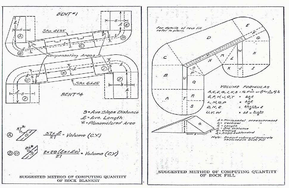
Rock fill, rock blanket, and revetment should be shown in the field book, and should include a sketch of the work involved, the actual computations, and a summary of quantities. Figure 239.15 also shows a method that may be used for computing the quantity of rock blanket.

Measurements and computations for paved ditch and similar items should be made as required by the specifications, with the comment “Field Measurement” shown where appropriate. Any changes in the pay quantity of processing should be shown, indicating that field measurement was made. Use sketches to show the areas or tabulate lengths of measurement.
Computations for sodding may be shown on these sheets if irregular areas are involved. If the measurements of sodding can be entered in a field book to show accurately the area sodded, it is satisfactory to compute the area of sodding in the field book. The quantity may then be shown on the appropriate 2B sheet. Computations for seeding, netting, glass fiber mat, fertilizing, mulching, and similar items may be made in this same manner.
239.16 Overhaul
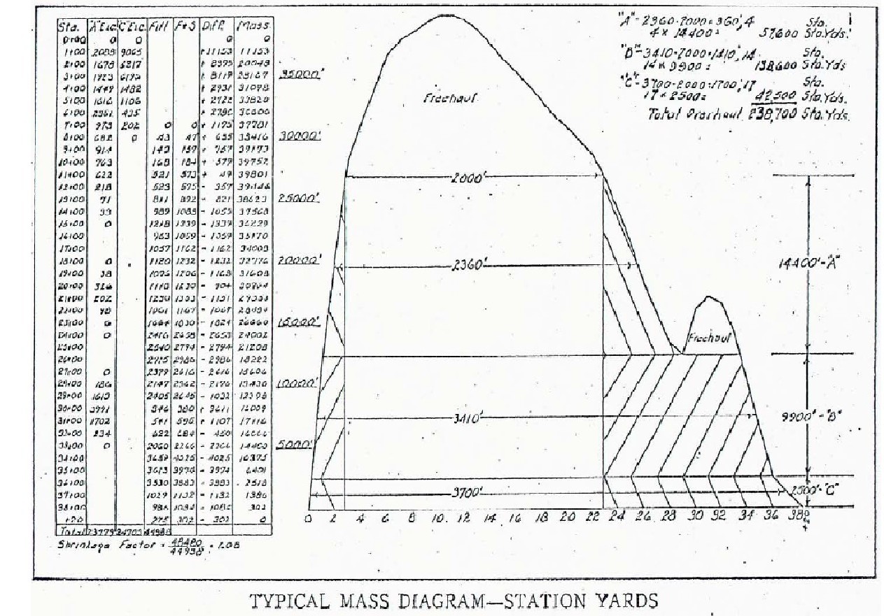
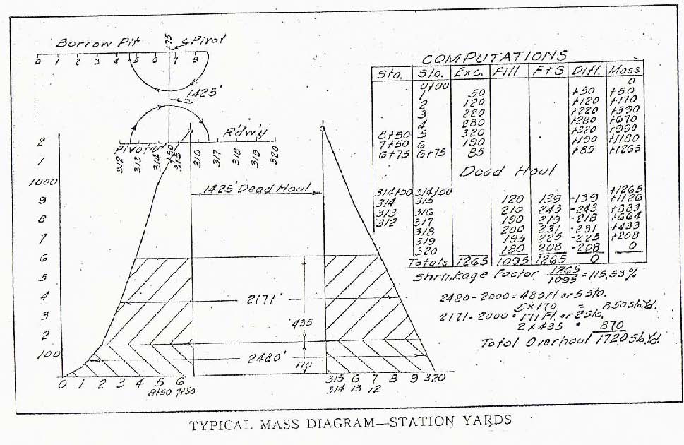
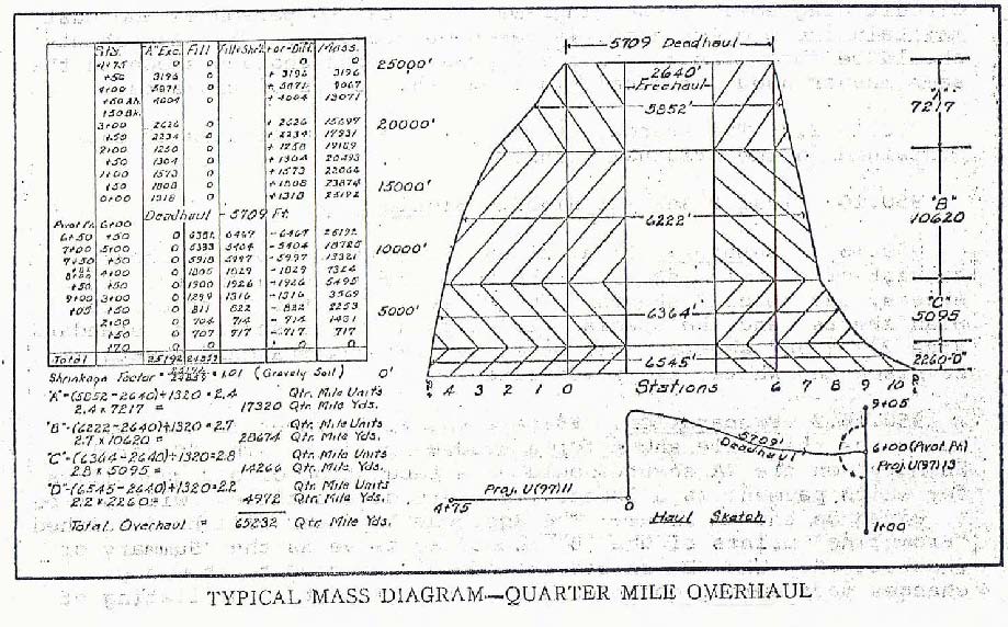
If satisfactory and accurate overhaul measurement is to be made, the inspector must know exactly how the material was moved. As outlined in Sec 205, payment for overhaul is usually on plan quantity basis, or the quantity is increased or decreased on a ratio basis. When neither method is applicable, it is necessary to recompute the overhaul by the use of a mass diagram. The computation of overhaul is not difficult once the basic principle is understood. It is the determination of the average volume of excavation that must be hauled a distance from the center of mass of the area involving excess excavation to the center of mass of the area involving excess embankment. The sample diagrams below may be used as a guide. The free haul distance will be stated in the specifications. For illustration, a 2000-ft. free haul has been used in Figures 239.16.1 and 239.16.2 and quarter mile free haul has been used in Figure 239.16.3.

Figure 239.16.1 shows a typical case of a balance containing rock excavation. It is some-times possible to draw separate mass diagrams for earth and for rock. This is perhaps the most accurate method of handling such balances. However, the rock formations often occur in intermittent seams making such procedure impractical. Therefore, the balance is usually handled as shown keeping in mind that the rock will actually swell and the earth shrink, but the combined factor may show a swell.

Figure 239.16.2 indicates hauling from a distant borrow pit into a roadway balance. This method shows folding the stationing back, or forward, about the intersection of the dead haul route with the stationing of the borrow pit haul route or the roadway centerline. The dead haul introduces no complications but will show as a break in the mass diagram.

Figure 239.16.3 shows the computation of quarter mile overhaul when material is taken from one project to another and hauled both ways from the point of entry. The same type of diagram may be used when hauling from the middle of a balance, with dead haul to a waste area. The principles for quarter mile yard overhaul are the same as for station yard, except that the free haul for quarter mile yard overhaul is 2640 ft.
The scale used in plotting mass diagrams must necessarily vary. It is suggested that a scale be chosen which will permit one diagram and accompanying computations to be placed on a single sheet of cross-section paper. If the overhaul is extensive or involved, the computations may be placed on one sheet and the mass diagram on another.
239.17 Final Plans For Highway Lighting
Final plans for lighting projects and lighting plans included within a larger roadway project are basically the same. Final plans for lighting projects will consist of a title sheet, 2A sheets, 2B sheets, plan sheets and a standard drawings index. They may also include special sheets as needed.
Corrections or revisions are to be done in Microstation. The 2A sheets should be created using Microstation and show all quantities for which payments are to be allowed. The 2B sheets serve as a summary of quantities and any changes made during construction of the project should be shown by correcting the 2B sheets.
The plan sheets are especially important since they serve both as a record of the location of the various items and as circuit diagrams. These diagrams are vital to personnel who must maintain the project after it has been accepted. All construction changes should be shown on the plan sheet drawing in the same manner used for final plans on other type projects.
239.18 Final Plans For Traffic Signals
Final plans for traffic signal projects and signal plans included within a larger roadway project are basically the same. Final plans for traffic signal projects will consist of a title sheet, 2A sheets, 2B sheets, symbol sheet, layout or plan sheets, phasing and sequence sheet and standard drawings index and possibly special sheets.
Corrections or revisions are to be done in Microstation. The 2A sheets should be created using Microstation and show all quantities for which payment is to be allowed. The 2B sheets will serve as a summary of quantities and any changes made during construction of the project should be shown by correcting the 2B sheets.
The plan sheets are especially important since they serve both as a record of the location of the various units and as circuit diagrams. These diagrams are vital to personnel who must maintain the project after it has been accepted. All construction changes should be shown on the plan sheet drawings in the same manner used for final plans on other type projects.
239.19 Final Plans For Highway Signing
Final plans for signing projects and signing plans included within a larger roadway project are principally the same. Final plans for highway signing projects will consist of a title sheet, 2A sheets, 2B sheets, plan sheets, special sign detail sheets, truss detail if applicable, sign cross section sheets and standard drawings index if applicable.
Corrections or revisions are to be done in Microstation. The 2A sheets should be created using Microstation and show all quantities for which payments are to be allowed. The 2B sheets serve as a summary of quantities and any changes made during construction of the project should be shown by correcting the 2B sheets.
The plan sheets and the special sign detail sheets should show all construction changes and modifications in the same manner used on final plans for roadway projects.
239.20 Final Plans For Miscellaneous Projects
For projects such as resurfacing, bridge painting, bridge rail and guard rail modifications, lane widening etc., where all plans are bound with the contract, the final plans are prepared by using a copy of the location sketch, length of project tabulation, typical section sheets, plan sheets and standard plans index. Show project information on all individual sheets. The 2A sheet should be created in Microstation on a 8½ in. x 11 in. sheet of paper. One copy of each sheet is to be submitted through the district to the Division of Construction. These final plans should also be signed and sealed by a P.E.

239.20.1 Plant Mix Bituminous Surface Leveling Course Projects
As-built drawings and the summary of final quantities are not required for this type project.
239.20.2 Pavement Repair Contracts
As-built drawings and summary of final quantities are not required for this type of project. Details of measurements and locations must be kept to document payments made.
239.21 Procedures For Checking Of Final Plans
239.21.1 Resident Engineer's Office
At the resident engineer's office, all items are to be computed, tabulated, and checked by project personnel. All items should be checked to ensure proper rounding based on the Unit “pay to” limits provided in the Bid Items Listing for Highway Construction. All quantities that involve transfer of field information from the original record to computation sheets or final plans, and the calculation of areas or volumes, shall be independently checked by at least one person in the project office, other than the individual making the initial calculations.
All items which are tabulated on the 2B sheets by location shall be independently cross-checked against the plan-profile sheets to determine that the listed pay items agree.
Items which require authorization by written record shall be checked against the documentation records in the file to determine that proper authority exists for payment purposes. Refer to the Payment Documentation Manual. Items paid as a contract or line item adjustment will require documentation to be sent in with the final plans.
Adding machine tapes or excel spreadsheet for all ticket quantities are to be properly identified and attached to the tickets that they represent. All tapes must include the symbol at the start of each column to indicate the machine was previously cleared. If the tape or spreadsheet total matches the total from computer-generated tickets, then no additional checking is required.
All totals shall be compared with the total quantities shown on the final estimate for payment purposes. They shall also be checked against summary of quantities on the 2A sheets. Tabulation of scale ticket data will be submitted to the district office with final plans. The individual load tickets will be retained at the project office, but may be requested by the district at any time.
Both the final estimate and the last change order shall be compared with the contract and all previously approved change orders to assure that the correct final quantities are indicated on the final estimate and that all changes are properly authorized and explained.
Although the renumbering of original drawings is not required, the numbering of sheets and the organization of the final plans shall be checked to confirm that they are arranged in the proper order. Also make sure the contract ID and Federal ID is on all sheets.
Each step in the checking process shall have the check indicated by a righthanded black check mark on the right side of the number being checked. Computations and plan sheets must include an identification of who made them or transcribed the data and who checked them. The signatures on the 2A sheets reflect that the entire set of final plans has been checked by a resident engineer staff, and reviewed and accepted by the resident engineer.
At the completion of the checking process, the resident engineer shall visually review the plans for compliance with specified procedures and policies affecting payment. When the resident engineer is satisfied that the final plans are satisfactory, the resident engineer shall complete, sign and date the upper portion of Final Plans Certification form concerning the preparation and checking of the final plans. The resident engineer should retain one copy of the form and transmit two copies to the district office with the final plans.
A letter from the RE showing the breakdown and/or explanation for extensions or adjustments of time. Refer to EPG 108.7.1 Extensions or Adjustments of Time.
The following is a list of items that should be included in final plans packages sent to the district office. Some items may not pertain to certain contracts.

- Final Estimate Item Detail
- Last Change Order
- 2A Sheets
- 2B Sheets
- Plan-profile Sheets (Bridge Sheets)
- Special Sheets
- Computation Sheets
- Field Notebook / List of Reported Quantities with Location
- Documentation for profile adjustments
- Documentation for superpave adjustments
- Invoices for partnering meetings
- Invoice for police enforcements
- Invoice and documentation of location for leftover materials
- Final plans certification
239.21.2 District Office
At the district office, checking is to be done on a random sampling basis intended to confirm that the preparation and checking of plans at the project level is meeting acceptable standards of neatness, arrangement and accuracy.
The extent that final plans require checking at the district office is not intended to be limited by the following instructions, but should in no case be less than that indicated herein.
For items that are computed, such as excavation, the district final plans and reports processor should visually review all data to detect any apparent errors in area or procedures. Approximately 5% of the data is selected at random and the computations checked. A check within the normal range of accuracy is to be accepted as an indication of the correctness of the computations. If appreciable errors are detected, the plans should be returned to the project office for review and correction.
For items such as base, asphaltic mixtures, etc. that are paid for on the basis of weight or volume and when all individual load tickets are submitted, the check is to be made by selecting at random not less than 5% of the tickets for each material, which are to be checked completely. The district will check all daily tickets submitted. If appreciable errors are detected, the plans should be returned to the project office for review and correction. Finally, the tabulation of quantities for each material shall be checked to determine if the final quantity allowed for payment is correct. These checks may be made by checking against the adding machine tapes or spreadsheet provided by the resident engineer.
Items such as PCC pavement, processing of base, etc. that are calculated on an area or linear basis will, in general, require checking only if there is a significant deviation from the original contract quantity.
For items authorized by documentation record, the files shall be checked to confirm that the district files contain copies of the necessary documentation records to confirm the quantities.
Approximately 5% of the various items tabulated on the 2B sheets by location shall be selected at random and cross-checked against the plan-profile sheets to verify that the listed pay quantities agree. Totals for each tabulation are to be checked.
All 2A sheet quantities shall be compared with 2B sheet totals, and any other applicable final quantities shown on other plan sheets, such as: lighting, signals, highway signing and bridge or documentation records.
All change orders shall be compared with the 2A sheet quantities.
All final payment estimate quantities will be compared with all change orders. If quantities were not updated by change order, they shall be compared with the contract.
Any plans in which errors are detected by this process shall be returned to the resident engineer for correction and complete review.
The items which the district final plans and reports processor actually checks in the specified process shall have this fact indicated by a left-handed red check mark on the left side of the number being checked. The presence of a red check mark shall indicate that the item has been checked for agreement with quantities and location shown on the next lower applicable document on the following list:
- Final Estimate Item Detail
- Last Change Order
- 2A Sheets
- 2B Sheets
- Plan-profile Sheets (Bridge Sheets)
- Special Sheets
- Computation Sheets
- Field Notebook / List of Final Quantities (Impromptu)
- Example: A check mark beside an excavation quantity on the 2B sheet indicates the quantity has been compared to the quantity shown on a plan-profile sheet, or a check mark on a change order indicates comparison to the 2A sheet.
When the checking process has been satisfactorily completed, the district final plans and reports processor shall complete and sign the center portion of Final Plans Certification form. One copy is to be retained by the district and one copy is to be transmitted to the Construction Division with the final plans.
The district checking shall always be indicated by red check marks even if someone other than the district final plans and reports processor performs the checking. Form C-FP1 must be signed by that person and accompanied by the assistant's title.
239.21.3 Construction Division
The final plans reviewer will confirm that final quantities are correct, all miscellaneous payments and deductions have been assessed according to the contract provisions, all required documentation has been completed and the as-built drawings have been prepared neatly, legibly and accurately.
The final estimate shall be compared with the change orders and the contract to assure that all quantities are correct.
The change orders are then compared with the final quantities.
Mathematical checks will be selectively performed as determined by the final plans reviewer. Specific items or projects may be selected at random for a thorough and detailed review. Additional documentation may be obtained in order to perform this comprehensive review.
The order record and documentation record files shall be checked to confirm that the division files contain the necessary documentation records and that all order records have been rescinded.
Upon completion of the review, the final plans reviewer shall complete and sign the lower portion of Final Plans Certification form. When a random check is made, the items checked shall be noted on the form. The completed form will be retained in the division file.
Any checks made by the final plans reviewer shall be indicated by a righthanded green check mark on the left side of the number being checked.
After the final cost of the project has been confirmed, the project finance allocation will be checked to see if sufficient funds are available for engineering and overruns.
In addition to reviewing the as-built plans, the final quantities and project documentation, the final plans reviewer is responsible for ensuring that provisions for final verification have been performed by others. These provisions necessarily vary by contract, but may include the following: DBE participation verification, certification of materials, settlement of claims by contractor and review of change order reasons by a field liaison engineer.
 |

|
| A set of final plans is a record as well as a graphic representation of a completed project | |