Difference between revisions of "751.32 Concrete Pile Cap Intermediate Bents"
Jump to navigation
Jump to search
m (attached article to new EPG 751) |
m (Per Bridge, expanded guidance for encased pile cap bent) |
||
| Line 96: | Line 96: | ||
== 751.32.3 Details == | == 751.32.3 Details == | ||
| + | ===751.32.3.1 Front Sheet=== | ||
| − | === 751.32.3. | + | {|border="0" cellpadding="3" align="center" |
| + | |- | ||
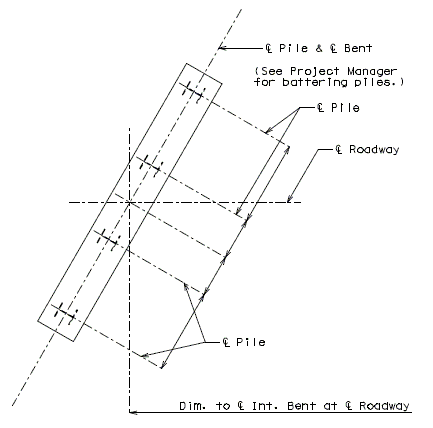
| + | |valign="top"|Note:||width="400pt"|The following are details and dimensions for the plan view of a typical pile cap bent on the front sheet of the bridge plans. Details and dimensions for an encased concrete pile cap bent are similar. | ||
| + | |- | ||
| + | | ||width="400pt"|Details for unsymmetrical roadways shall require dimensions tying Centerline Lane to Centerline Structure. | ||
| + | |} | ||
| + | |||
| + | |||
| + | <center>[[Image:751.32 details-front sheet plan of int bent.gif]]</center> | ||
| + | |||
| + | === 751.32.3.2 Typical Pile Cap Bent === | ||
{|border="0" cellpadding="5" align="center" style="text-align:center" cellspacing="0" | {|border="0" cellpadding="5" align="center" style="text-align:center" cellspacing="0" | ||
| Line 119: | Line 130: | ||
|- | |- | ||
|valign="top"|[[Image:751.32 circled 4.gif]] | |valign="top"|[[Image:751.32 circled 4.gif]] | ||
| − | |width="500" align="left"|If the depth at the end of the beam, due to the steps, exceeds 4 | + | |width="500" align="left"|If the depth at the end of the beam, due to the steps, exceeds 4'-6", the beam bottom should be stepped or sloped. |
|- | |- | ||
|valign="top"|[[Image:751.32 circled 5.gif]] | |valign="top"|[[Image:751.32 circled 5.gif]] | ||
| Line 128: | Line 139: | ||
|} | |} | ||
| − | === 751.32.3. | + | === 751.32.3.3 Encased Pile Cap Bent=== |
| − | {|border="0" cellpadding=" | + | Consideration shall be given to [http://epg.modot.org/index.php?title=751.1_Preliminary_Design#751.1.2.19_Substructure_Type EPG 751.1.2.19 Substructure Type] before using this type of structure. |
| + | |||
| + | {|border="0" cellpadding="5" align="center" style="text-align:center" cellspacing="0" | ||
| + | |- | ||
| + | |[[Image:751.32.3.3.1.jpg|center|750px]] | ||
| + | |- | ||
| + | !'''Part Elevation''' | ||
|- | |- | ||
| − | | | + | |[[Image:751.32.3.3.2.jpg|center|300px]] |
|- | |- | ||
| − | | ||width=" | + | !'''Part Section''' |
| + | |} | ||
| + | {|border="0" cellpadding="5" align="center" style="text-align:center" cellspacing="0" | ||
| + | |- | ||
| + | |valign="top"|[[Image:751.32 circled 1.gif]] | ||
| + | |width="500" align="left"|Use 2'-6" minimum or as determined by the superstructure requirements or the minimum support length required for earthquake criteria (expansion joint bents only) (3" increments). | ||
| + | |- | ||
| + | |valign="top"|[[Image:751.32 circled 2.gif]] | ||
| + | |width="500" align="left"|= 2'-9" (Min.) for Wide Flange and Double-Tee Girders or,<br/> 3'-0" (Min.) for Prestressed Girders and Plate Girders. | ||
| + | |- | ||
| + | |valign="top"|[[Image:751.32 circled 3.gif]] | ||
| + | |width="500" align="left"|Check the clearance of the anchor bolt well to the top of pile. Increase the beam depth if needed. | ||
| + | |- | ||
| + | |valign="top"|[[Image:751.32 circled 4.gif]] | ||
| + | |width="500" align="left"|If the depth at the end of the beam, due to the steps, exceeds 4'-6", the beam bottom should be stepped or sloped. | ||
| + | |- | ||
| + | |valign="top"|[[Image:751.32 circled 5.gif]] | ||
| + | |width="500" align="left"|Height by design. Embed encasement 2 ft. (min.) below the top of the lowest finished groundline elevation, unless a greater embedment is required for bridge design. | ||
| + | |- | ||
| + | |valign="top"|[[Image:751.32 circled 6.gif]] | ||
| + | |width="500" align="left"|Minimum of 3 piles at 10'-0" cts., maximum spacing (1" increments). | ||
|} | |} | ||
| − | |||
| − | |||
== 751.32.4 Reinforcement == | == 751.32.4 Reinforcement == | ||
| − | + | === 751.32.4.1 Typical Pile Cap Bent === | |
| − | === 751.32.4.1 | ||
{|border="0" cellpadding="5" align="center" style="text-align:center" cellspacing="0" | {|border="0" cellpadding="5" align="center" style="text-align:center" cellspacing="0" | ||
| Line 200: | Line 234: | ||
!colspan="2"|Longitudinal Beam Steps | !colspan="2"|Longitudinal Beam Steps | ||
|} | |} | ||
| + | |||
| + | === 751.32.4.2 Encased Pile Cap Bent=== | ||
| + | |||
| + | Supplemental details for encased pile cap bents are provided. | ||
| + | |||
| + | {|border="0" cellpadding="5" align="center" style="text-align:center" cellspacing="0" | ||
| + | |- | ||
| + | |[[image:751.32.4.2 part elev.jpg|center|750px]] | ||
| + | |- | ||
| + | |align="center"|'''Part Elevation''' | ||
| + | |} | ||
| + | |||
| + | {|border="0" cellpadding="5" align="center" style="text-align:center" cellspacing="0" | ||
| + | |- | ||
| + | |[[image:751.32.4.2 part section.jpg|center|450px]] | ||
| + | |- | ||
| + | |align="center"|'''Part Section''' | ||
| + | |} | ||
| + | |||
| + | {|border="0" cellpadding="5" align="center" style="text-align:center" cellspacing="0" | ||
| + | |- | ||
| + | |[[image:751.32.4.2 part plan.jpg|center|650px]] | ||
| + | |- | ||
| + | |align="center"|'''Part Plan''' | ||
| + | |} | ||
| + | |||
| + | {|border="0" cellpadding="3" align="center" cellspacing="0" | ||
| + | |- | ||
| + | |valign="top"|Note:||width="500pt" align="left" valign="top"|Locate #4 bars "[[Image:751.32 reinforcement--4 bar under bearing.gif]]" under bearings where required to maintain a 6" maximum spacing of combined stirrups. (#4 bars "[[Image:751.32 reinforcement--4 bar under bearing.gif]]" are not required for Double-Tee Structures.) | ||
| + | |- | ||
| + | | ||width="500pt"|When an expansion device is used at an intermediate bent, all reinforcement located entirely within the beam or extending into the beam shall be epoxy coated. | ||
| + | |} | ||
| + | |||
[[Category:751 LRFD Bridge Design Guidelines]] | [[Category:751 LRFD Bridge Design Guidelines]] | ||
Revision as of 12:29, 26 October 2011
751.32.1 General
751.32.1.1 Material Properties
| Concrete | |||
|---|---|---|---|
| Typically, shall consist of: | |||
| Class B Concrete (Substructure) | = 3.0 ksi | ||
| = 10 | |||
In addition, Class B-1 Concrete (Substructure) may also be used in special cases (See Project Manager). The following equations shall apply to both concrete classes:
Concrete modulus of elasticity:
Where:
| = unit weight of non-reinforced concrete = 0.145 kcf | |
| = correction factor for source of aggregate = 1.0 |
| Modulus of Rupture: | For minimum reinforcement, | |
| For all other calculations, | ||
| is in units of ksi |
Reinforcing Steel
| Minimum yield strength, | = 60.0 ksi | |
| Steel modulus of elasticity, | = 29000 ksi |
751.32.2 Design
751.32.2.1 Limit States and Factors
In general, each component shall satisfy the following equation:
Where:
| = Total factored force effect | |
| = Force effect | |
| = Load modifier | |
| = Load factor | |
| = Resistance factor | |
| = Nominal resistance | |
| = Factored resistance |
Limit States
The following limit states shall be considered for bent design:
- STRENGTH – I
- STRENGTH – III
- STRENGTH – IV
- STRENGTH – V
- SERVICE – I
- FATIGUE
See LRFD Table 3.4.1-1 and LRFD 3.4.2 for Loads and Load Factors applied at each given limit state.
Resistance factors
- STRENGTH limit states, see LRFD 5.5.4.2
- For all other limit states, = 1.00
751.32.3 Details
751.32.3.1 Front Sheet
| Note: | The following are details and dimensions for the plan view of a typical pile cap bent on the front sheet of the bridge plans. Details and dimensions for an encased concrete pile cap bent are similar. |
| Details for unsymmetrical roadways shall require dimensions tying Centerline Lane to Centerline Structure. |

751.32.3.2 Typical Pile Cap Bent
 |

|
| (*) 3" (Typ.) | |
| Part Elevation | Part Section |
|---|---|
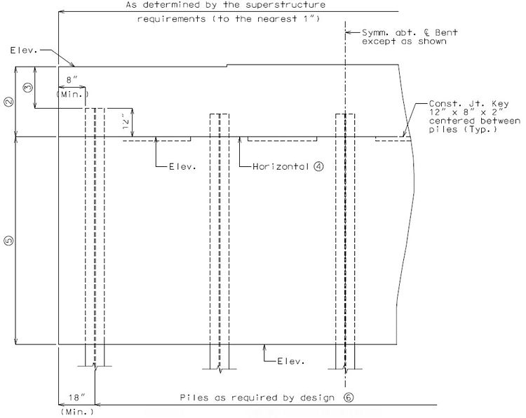
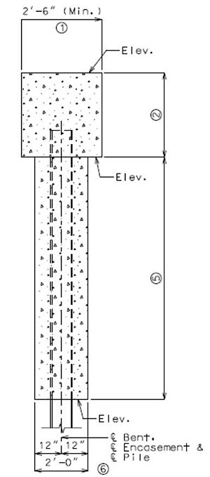
751.32.3.3 Encased Pile Cap Bent
Consideration shall be given to EPG 751.1.2.19 Substructure Type before using this type of structure.
| Part Elevation |
|---|
| Part Section |
751.32.4 Reinforcement
751.32.4.1 Typical Pile Cap Bent
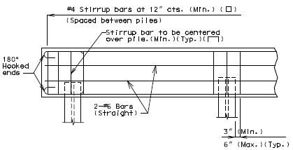
|
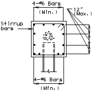
|
| Part Elevation | Section Thru Beam |
|---|---|

|
|
| Part Plan | |
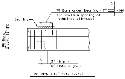
|
|
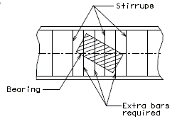
| * #4 Bars ( | |
| Reinforcement Under Bearings | |
|---|---|

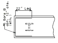
| |
| Transverse Beam Steps - Over 3" or Steps Accumulating Over 3" | |
| |
| Part Plan | |
|---|---|

| |
| Over 3" thru 12" | Over 12" |
| Longitudinal Beam Steps | |
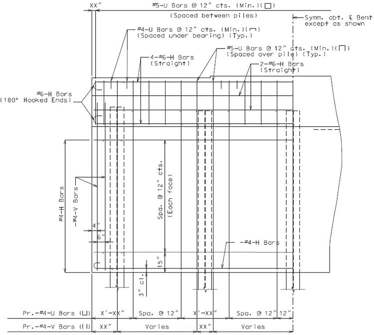
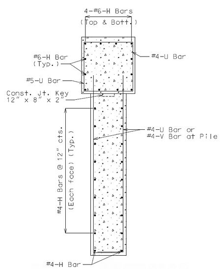
751.32.4.2 Encased Pile Cap Bent
Supplemental details for encased pile cap bents are provided.
| Part Elevation |
| Part Section |
| Part Plan |


![{\displaystyle \,E_{c}=33000K_{l}w_{c}{\sqrt[{1.5}]{f'_{c}}}}](https://wikimedia.org/api/rest_v1/media/math/render/svg/d6f7179fdd00184aa150702025a6dfb989802a62)


