751.24 Retaining Walls: Difference between revisions
m Per BR, numerous minor clarifications related to barrier pay items |
→751.24.2.1 Design: updated per RR4023 |
||
| (18 intermediate revisions by 2 users not shown) | |||
| Line 1: | Line 1: | ||
<div style="float: right; margin-left: 30px; margin-bottom: 30px;">__TOC__</div> | |||
==751.24.1 General== | ==751.24.1 General== | ||
{|style="padding: 0.3em; margin-left:6px; border:2px solid #a9a9a9; text-align:center; font-size: 95%; background:#f5f5f5" width="160px" align="right" | {| style="padding: 0.3em; margin-left:6px; border:2px solid #a9a9a9; text-align:center; font-size: 95%; background:#f5f5f5" width="160px" align="right" | ||
|- | |- | ||
|'''Additional Information''' | | '''Additional Information''' | ||
|- | |- | ||
| | | LRFD 11 | ||
|} | |} | ||
Retaining wall shall be designed to withstand lateral earth and water pressures, including any live and dead load surcharge, the self weight of the wall, temperature and shrinkage effect, live load and collision forces, and earthquake loads in accordance with the general principles of | For understanding the equivalency of seismic design category (SDC) and seismic zone for LRFD, see [[751.9_Bridge_Seismic_Design#751.9.1.1_Applicability_of_Guidelines_and_Seismic_Design_Philosophy|EPG 751.9.1.1]] and [https://epg.modot.org/forms/general_files/BR/Bridge_Seismic_Design_Flowchart.pdf Bridge Seismic Design Flowchart]. | ||
Retaining wall shall be designed to withstand lateral earth and water pressures, including any live and dead load surcharge, the self weight of the wall, temperature and shrinkage effect, live load and collision forces, and earthquake loads in accordance with the general principles of LRFD Section 11 and the general principles specified in this article. | |||
Seismic analysis provisions shall not be ignored for walls that support another structure (i.e. support abutment fill or building) in SDC B or C (seismic zone 2 or 3). No-seismic-analysis provisions may be considered for walls that do not support another structure (i.e. most of District walls) in SDC B or C (seismic zone 2 or 3) in accordance with LRFD 11.5.4.2 and Geotech report. Seismic analysis provisions shall not be ignored for walls in SDC D (seismic zone 4). | |||
===751.24.1.1 Wall Type Selection=== | ===751.24.1.1 Wall Type Selection=== | ||
{|style="padding: 0.3em; margin-left:5px; border:2px solid #a9a9a9; text-align:center; font-size: 95%; background:#f5f5f5" width="160px" align="right" | {| style="padding: 0.3em; margin-left:5px; border:2px solid #a9a9a9; text-align:center; font-size: 95%; background:#f5f5f5" width="160px" align="right" | ||
|- | |- | ||
|'''Additional Information''' | | '''Additional Information''' | ||
|- | |- | ||
| | | LRFD 11 | ||
|} | |} | ||
Selection of wall type shall be based on an assessment of the magnitude and direction of loading, depth to suitable foundation support, potential for earthquake loading, presence of deleterious environmental factors, wall site cross-sectional geometry, proximity of physical constraints, tolerable and differential settlement, facing appearance and ease and cost of construction. | Selection of wall type shall be based on an assessment of the magnitude and direction of loading, depth to suitable foundation support, potential for earthquake loading, presence of deleterious environmental factors, wall site cross-sectional geometry, proximity of physical constraints, tolerable and differential settlement, facing appearance and ease and cost of construction. | ||
| Line 34: | Line 33: | ||
{|style="padding: 0.3em; margin-left:5px; border:2px solid #a9a9a9; text-align:center; font-size: 95%; background:#f5f5f5" width="160px" align="right" | {|style="padding: 0.3em; margin-left:5px; border:2px solid #a9a9a9; text-align:center; font-size: 95%; background:#f5f5f5" width="160px" align="right" | ||
|- | |- | ||
|'''Additional Information''' | | '''Additional Information''' | ||
|- | |- | ||
| | |LRFD 11.10,</br>FHWA-NHI-10-024 and 025 | ||
|} | |} | ||
MSE retaining walls use precast block or panel like facing elements combined with either metallic or geosynthetic tensile reinforcements in the soil mass. MSE walls are preferred over cast-in-place walls because they are usually more economical. Other advantages include a wide variety of design styles, ease and speed of installation, and their ability to accommodate total and differential settlements. Wall design heights upwards of 80 ft. are technically feasible (FHFW-SA-96-071). MSE walls may be used to retain fill for end bents of bridge structures. | MSE retaining walls use precast block or panel like facing elements combined with either metallic or geosynthetic tensile reinforcements in the soil mass. MSE walls are preferred over cast-in-place walls because they are usually more economical. Other advantages include a wide variety of design styles, ease and speed of installation, and their ability to accommodate total and differential settlements. Wall design heights upwards of 80 ft. are technically feasible (FHFW-SA-96-071). MSE walls may be used to retain fill for end bents of bridge structures. | ||
Situations exist where the use of MSE walls is either limited or not recommended. Some obstacles such as drop inlets, sign truss pedestals or footings, and fence posts may be placed within the soil reinforcement area, however, these obstacles increase the difficulty and expense of providing sufficient soil reinforcement for stability. Box culverts and highway drainage pipes may run through MSE walls, but it is preferable not to run the pipes close to or parallel to the walls. Utilities other than highway drainage should not be constructed within the soil reinforcement area. Be cautious when using MSE walls in a | Situations exist where the use of MSE walls is either limited or not recommended. Some obstacles such as drop inlets, sign truss pedestals or footings, and fence posts may be placed within the soil reinforcement area, however, these obstacles increase the difficulty and expense of providing sufficient soil reinforcement for stability. Box culverts and highway drainage pipes may run through MSE walls, but it is preferable not to run the pipes close to or parallel to the walls. Utilities other than highway drainage should not be constructed within the soil reinforcement area. Be cautious when using MSE walls in a floodplain. A flood could cause scouring around the reinforcement and seepage of the backfill material. Soil reinforcements should not be used where exposure to ground water contaminated by acid mine drainage or other industrial pollutants as indicated by a low pH and high chlorides and sulfates exist. Galvanized metallic reinforcements shall not be used where stray electrical ground currents could occur as would be present near an electrical substation. | ||
Sufficient right of way is required to install the soil reinforcement which extends into the backfill area at least 8 feet, 70 percent of the wall height or as per design requirements, whichever is greater. For more information regarding soil reinforcement length | Sufficient right of way is required to install the soil reinforcement which extends into the backfill area at least 8 feet, 70 percent of the wall height or as per design requirements set forth in [[751.6 General Quantities#751.6.2.17 Excavation|EPG 751.6.2.17 Excavation]], whichever is greater. For more information regarding soil reinforcement length, excavation limits and Minimum Embedment Depth of MSEW, see [[751.6 General Quantities#751.6.2.17 Excavation|EPG 751.6.2.17 Excavation]]. | ||
Finally, barrier curbs constructed over or in line with the front face of the wall shall have adequate room provided laterally between the back of the wall facing and the curb or slab so that load is not directly transmitted to the top of MSE wall or facing units. | |||
---- | |||
<div style="text-align: center; margin-left: auto; margin-right: auto;"> | |||
<gallery mode=packed widths=200px heights=200px> | |||
File:751.24.1.1_barrier_top_MSE_wall-01.jpg| '''Barrier at Top of MSE Wall''' | |||
File:blank.jpg| | |||
File:751.24.1.1_barrier_front_MSE_wall-01.jpg| '''Barrier in Front of MSE Wall''' | |||
</gallery> | |||
</div> | |||
---- | |||
'''Concrete Cantilever Wall on Spread Footing''' | '''Concrete Cantilever Wall on Spread Footing''' | ||
| Line 62: | Line 65: | ||
'''Concrete Cantilever Wall on Pile Footing''' | '''Concrete Cantilever Wall on Pile Footing''' | ||
Concrete cantilever walls on pile footings are used when the soil conditions do not permit the use of spread footings. These walls are also used when an end bent requires wings longer than 22 feet. In these cases a stub wing is left attached to the end bent and the rest of the wing is detached to become a retaining wall. | Concrete cantilever walls on pile footings are used when the soil conditions do not permit the use of spread footings. These walls are also used when an end bent requires wings longer than 22 feet for seismic category A or 17 ft. for seismic category B, C or D. In these cases a stub wing is left attached to the end bent and the rest of the wing is detached to become a retaining wall as shown in [[751.35_Concrete_Pile_Cap_Integral_End_Bents#751.35.3.5_Wing_and_Detached_Wing_Walls|751.35.3.5 Wing and Detached Wing Walls]]. | ||
'''Concrete L-Shaped Retaining Wall on Spread Footings''' | '''Concrete L-Shaped Retaining Wall on Spread Footings''' | ||
| Line 71: | Line 74: | ||
===751.24.1.2 Loads=== | ===751.24.1.2 Loads=== | ||
Conventional retaining walls: Loads shall be determined in accordance with LRFD 3 and 11.6. | |||
MSE retaining walls: Loads shall be determined in accordance with LRFD 3 and 11.10. | |||
Note: For guidance, follow the [[751.40_LFD_Widening_and_Repair#751.40.8.15_Cast-In-Place_Concrete_Retaining_Walls|751.40.8.15 Cast -In-Place Concrete Retaining Walls]] and modify guidance of ASD as necessary to meet LRFD requirements until this section is modified for LRFD. | |||
'''Dead Loads''' | '''Dead Loads''' | ||
| Line 76: | Line 84: | ||
Dead loads shall be determined from the unit weights in [[751.2 Loads#751.2.1.1 Dead Load |EPG 751.2.1.1 Dead Load]]. | Dead loads shall be determined from the unit weights in [[751.2 Loads#751.2.1.1 Dead Load |EPG 751.2.1.1 Dead Load]]. | ||
==751.24.2 Mechanically Stabilized Earth (MSE) Walls== | |||
===751.24.2.1 Design=== | |||
Designs of Mechanically Stabilized Earth (MSE) walls shall be completed by consultants or contractors in accordance with Section 11.10 of LRFD specifications, FHWA-NHI-10-024 and FHWA-NHI-10-025 for LRFD. [https://www.modot.org/bridge-pre-qualified-products-list Bridge Pre-qualified Products List (BPPL)] provided on MoDOT's web page and in Sharepoint contains a listing of facing unit manufacturers, soil reinforcement suppliers, and wall system suppliers which have been approved for use. See [http://www.modot.org/business/standards_and_specs/SpecbookEPG.pdf#page=11 Sec 720] and [http://www.modot.org/business/standards_and_specs/SpecbookEPG.pdf#page=14 Sec 1010] for additional information. The Geotechnical Section is responsible for checking global stability of permanent MSE wall systems, which should be reported in the Foundation Investigation Geotechnical Report. For MSE wall preliminary information, see [[751.1_Preliminary_Design#751.1.4.3_MSE_Walls|EPG 751.1.4.3 MSE Walls]]. For design requirements of MSE wall systems and temporary shoring (including temporary MSE walls), see [[:Category:720_Mechanically_Stabilized_Earth_Wall_Systems#720.2_Design_Requirements|EPG 720 Mechanically Stabilized Earth Wall Systems]]. For staged bridge construction, see [[751.1_Preliminary_Design#751.1.2.11_Staged_Construction|EPG 751.1.2.11 Staged Construction]]. | |||
For seismic design requirements, see [https://epg.modot.org/forms/general_files/BR/Bridge_Seismic_Design_Flowchart.pdf Bridge Seismic Design Flowchart]. References for consultants and contractors include Section 11.10 of LRFD, FHWA-NHI-10-024 and FHWA-NHI-10-025. | |||
'''Design Life''' | |||
* 75 year minimum for permanent walls (if retained foundation require 100 year than consider 100 year minimum design life for wall). | |||
: | '''Global stability:''' | ||
Global stability will be performed by Geotechnical Section or their agent. | |||
'''MSE wall contractor/designer responsibility:''' | |||
MSE wall contractor/designer shall perform following analysis in their design for all applicable limit states. | |||
:* External Stability | |||
::* Limiting Eccentricity | |||
::* Sliding | |||
::* Factored Bearing Pressure/Stress ≤ Factored Bearing Resistance | |||
:* Internal Stability | |||
::* Tensile Resistance of Reinforcement | |||
::* Pullout Resistance of Reinforcement | |||
::* Structural Resistance of Face Elements | |||
::* Structural Resistance of Face Element Connections | |||
:* Compound Stability | |||
:: Capacity/Demand ratio (CDR) for bearing capacity shall be ≥ 1.0 | |||
:: <math>Bearing\ Capacity\ (CDR) = \frac{Factored\ Bearing\ Resistance}{Maximum\ Factored\ Bearing\ Stress} \ge 1.0</math> | |||
:: Strength Limit States: | |||
:: Factored bearing resistance = Nominal bearing resistance from Geotech report X Minimum Resistance factor (0.65, Geotech report) LRFD Table 11.5.7-1 | |||
: | :: Extreme Event I Limit State: | ||
:: Factored bearing resistance = Nominal bearing resistance from Geotech report X Resistance factor | |||
:: Resistance factor = 0.9 LRFD 11.8.6.1 | |||
: | :: Factored bearing stress shall be computed using a uniform base pressure distribution over an effective width of footing determined in accordance with the provisions of LRFD 10.6.3.1 and 10.6.3.2, 11.10.5.4 and Figure 11.6.3.2-1 for foundation supported on soil or rock. | ||
: | :: B’ = L – 2e | ||
: | :: Where, | ||
::: L = Soil reinforcement length (For modular block use B in lieu of L as per LRFD 11.10.2-1) | |||
::: B’ = effective width of footing | |||
::: e = eccentricity | |||
::: Note: When the value of eccentricity e is negative then B´ = L. | |||
::Capacity/Demand ratio (CDR) for overturning shall be ≥ 1.0 | |||
::<math>Overtuning\ (CDR) = \frac{Total\ Factored\ Resisting\ Moment}{Total\ Factored\ Driving\ Moment} \ge 1.0</math> | |||
::Capacity/Demand ratio (CDR) for eccentricity shall be ≥ 1.0 | |||
::<math>Eccentricity\ (CDR) = \frac{e_{Limit}}{e_{design}} \ge 1.0</math> | |||
::Capacity/Demand ratio (CDR) for sliding shall be ≥ 1.0 LRFD 11.10.5.3 & 10.6.3.4 | |||
::<math>Sliding\ (CDR) = \frac{Total\ Factored\ Sliding\ Resistance}{Total\ Factored\ Active\ Force} \ge 1.0</math> | |||
::Capacity/Demand ratio (CDR) for internal stability shall be ≥ 1.0 | |||
::Eccentricity, (e) Limit for Strength Limit State: LRFD 11.6.3.3 & C11.10.5.4 | |||
::: For foundations supported on soil or rock, the location of the resultant of the reaction forces shall be within the middle two-thirds of the base width, L or (e ≤ 0.33L). | |||
::Eccentricity, (e) Limit for Extreme Event I (Seismic): LRFD 11.6.5.1 | |||
:::For foundations supported on soil or rock, the location of the resultant of the reaction forces shall be within the middle two-thirds of the base width, L or (e ≤ 0.33L) for γ<sub>EQ</sub> = 0.0 and middle eight-tenths of the base width, L or (e ≤ 0.40L) for γ<sub>EQ</sub> = 1.0. For γ<sub>EQ</sub> between 0.0 and 1.0, interpolate e value linearly between 0.33L and 0.40L. For γ<sub>EQ</sub> refer to LRFD 3.4. | |||
:::Note: Seismic design shall be performed for γ<sub>EQ</sub> = 0.5 | |||
::Eccentricity, (e) Limit for Extreme Event II: | |||
:::For foundations supported on soil or rock, the location of the resultant of the reaction forces shall be within the middle eight-tenths of the base width, L or (e ≤ 0.40L). | |||
'''General Guidelines''' | |||
* Drycast modular block wall (DMBW-MSE) systems are limited to a 10 ft. height in one lift. | |||
* Wetcast modular block wall (WMBW-MSE) systems are limited to a 15 ft. height in one lift. | |||
* For Drycast modular block wall (DMBW-MSE) systems and Wetcast modular block wall (WMBW-MSE) systems, top cap units shall be used and shall be permanently attached by means of a resin anchor system. | |||
* For precast modular panel wall (PMPW-MSE) systems, capstone may be substituted for coping and either shall be permanently attached to wall by panel dowels. | |||
* For precast modular panel wall (PMPW-MSE) systems, form liners are required to produce all panels. Using form liner to produce panel facing is more cost effective than producing flat panels. Standard form liners are specified on the [https://www.modot.org/mse-wall-msew MSE Wall Standard Drawings]. Be specific regarding names, types and colors of staining, and names and types of form liner. | |||
* MSE walls shall not be used where exposure to acid water may occur such as in areas of coal mining. | |||
* MSE walls shall not be used where scour is a problem. | |||
* MSE walls with metallic soil reinforcement shall not be used where stray electrical ground currents may occur as would be present near electrical substations. | |||
* No utilities shall be allowed in the reinforced earth if future access to the utilities would require that the reinforcement layers be cut, or if there is a potential for material, which can cause degradation of the soil reinforcement, to leak out of the utilities into the wall backfill, with the exception of storm water drainage. | |||
* All vertical objects shall have at least 4’-6” clear space between back of the wall facing and object for select granular backfill compaction and soil reinforcement skew limit requirements. For piles, see pipe pile spacers guidance. | |||
* The interior angle between two MSE walls should be greater than 70°. However, if unavoidable, then place [[751.50_Standard_Detailing_Notes#J._MSE_Wall_Notes_.28Notes_for_Bridge_Standard_Drawings.29|EPG 751.50 J1.41 note]] on the design plans. | |||
* Drycast modular block wall (DMBW-MSE) systems and Wetcast modular block wall (WMBW-MSE) systems may be battered up to 1.5 in. per foot. Modular blocks are also known as “segmental blocks”. | |||
* The friction angle used for the computation of horizontal forces within the reinforced soil shall be greater than or equal to 34°. | |||
* For epoxy coated reinforcement requirements, see [[751.5 Structural Detailing Guidelines#751.5.9.2.2 Epoxy Coated Reinforcement Requirements|EPG 751.5.9.2.2 Epoxy Coated Reinforcement Requirements]]. | |||
* All concrete except facing panels or units shall be CLASS B or B-1. | |||
* The friction angle of the soil to be retained by the reinforced earth shall be listed on the plans as well as the friction angle for the foundation material the wall is to rest on. | |||
: | * The following requirement shall be considered (from 2009_FHWA-NHI-10-024 MSE wall 132042.pdf, page 200-201) when seismic design is required: | ||
:* For seismic design category, SDC C or D (Zones 3 or 4), facing connections in modular block faced walls (MBW) shall use shear resisting devices (shear keys, pin, etc.) between the MBW units and soil reinforcement, and shall not be fully dependent on frictional resistance between the soil reinforcement and facing blocks. For connections partially dependent on friction between the facing blocks and the soil reinforcement, the nominal long-term connection strength T<sub>ac</sub>, should be reduced to 80 percent of its static value. | |||
* Seismic design category and acceleration coefficients shall be listed on the plans for categories B, C and D. If a seismic analysis is required that shall also be noted on the plans. See [[751.50_Standard_Detailing_Notes#A._General_Notes|EPG 751.50 A1.1 note]]. | |||
* Plans note ([[751.50_Standard_Detailing_Notes#J._MSE_Wall_Notes_.28Notes_for_Bridge_Standard_Drawings.29|EPG 751.50 J1.1]]) is required to clearly identify the responsibilities of the wall designer. | |||
* Do not use Drycast modular block wall (DMBW-MSE) systems in the following locations: | |||
::* Within the splash zone from snow removal operations (assumed to be 15 feet from the edge of the shoulder). | |||
: | ::* Where the blocks will be continuously wetted, such as around sources of water. | ||
: | ::* Where blocks will be located behind barrier or other obstacles that will trap salt-laden snow from removal operations. | ||
: | * Do not use Drycast modular block wall (DMBW-MSE) systems or Wetcast modular block wall (WMBW-MSE) systems in the following locations: | ||
::* For structurally critical applications, such as containing necessary fill around structures. | |||
::* In tiered wall systems. | |||
* For locations where Drycast modular block wall (DMBW-MSE) systems and Wetcast modular block wall (WMBW-MSE) systems are not desirable, consider coloring agents and/or architectural forms using precast modular panel wall (PMPW-MSE) systems for aesthetic installations. | |||
* For slab drain location near MSE Wall, see [[751.10 General Superstructure#General Requirements for Location and Spacing of Slab Drains|EPG 751.10.3.1 Drain Type, Alignment and Spacing]] and [[751.10 General Superstructure#751.10.3.3 General Requirements for Location of Slab Drains|EPG 751.10.3.3 General Requirements for Location of Slab Drains]]. | |||
| | |||
| | |||
* Roadway runoff should be directed away from running along face of MSE walls used as wing walls on bridge structures. | |||
* Drainage: | |||
: | :*Gutter type should be selected at the core team meeting. | ||
:: | :* When gutter is required without fencing, use Type A or Type B gutter (for detail, see [https://www.modot.org/media/16880 Std. Plan 609.00]). | ||
:: | :* When gutter is required with fencing, use Modified Type A or Modified Type B gutter (for detail, see [https://www.modot.org/media/16871 Std. Plan 607.11]). | ||
:* When fencing is required without gutter, place in tube and grout behind the MSE wall (for detail, see [https://www.modot.org/bridge-standard-drawings MSE Wall Standard Drawings - MSEW], Fence Post Connection Behind MSE Wall (without gutter). | |||
:* Lower backfill longitudinal drainage pipes behind all MSE walls shall be two-6” (Min.) diameter perforated PVC or PE pipe (See Sec 1013) unless larger sizes are required by design which shall be the responsibility of the District Design Division. Show drainage pipe size on plans. Outlet screens and cleanouts should be detailed for any drain pipe (shown on MoDOT MSE wall plans or roadway plans). Lateral non-perforated drain pipes (below leveling pad) are permitted by Standard Specifications and shall be sized by the District Design Division if necessary. Lateral outlet drain pipe sloped at 2% minimum. | |||
::* Identify on MSE wall plans or roadway plans drainage pipe point of entry, point of outlet (daylighting), 2% min. drainage slopes in between points to ensure positive flow and additional longitudinal drainage pipes if required to accommodate ground slope changes and lateral drainage pipes if required by design. | |||
::* Adjustment in the vertical alignment of the longitudinal drainage pipes from that depicted on the MSE wall standard drawings may be necessary to ensure positive flow out of the drainage system. | |||
::* Identify on MSE wall plans or roadway plans the outlet ends of pipes which shall be located to prevent clogging or backflow into the drainage system. Outlet screens and cleanouts should be detailed for any drain pipe. | |||
[[ | :* For more information on drainage, see [[#Drainage at MSE Walls|Drainage at MSE Walls]]. | ||
'''MSE Wall Construction: Pipe Pile Spacers Guidance''' | |||
For bridges not longer than 200 feet, pipe pile spacers or pile jackets shall be used at pile locations behind mechanically stabilized earth walls at end bents. Corrugated pipe pile spacers are required when the wall is built prior to driving the piles to protect the wall reinforcement when driving pile for the bridge substructure at end bents(s). Pile spacers or pile jackets may be used when the piles are driven before the wall is built. Pipe pile spacers shall have an inside diameter greater than that of the pile and large enough to avoid damage to the pipe when driving the pile. Use [[751.50 Standard Detailing Notes#E1. Excavation and Fill|EPG 751.50 Standard Detailing Note E1.2a]] on bridge plans. | |||
[[ | For bridges longer than 200 feet, pipe pile spacers are required and the pile spacer shall be oversized to mitigate the effects of bridge thermal movements on the MSE wall. For HP12, HP14, CIP 14” and CIP 16” piles provide 24-inch inside diameter of pile spacer for bridge movement. Minimum pile spacing shall be 5 feet to allow room for compaction of the soil layers. Use [[751.50 Standard Detailing Notes#E1. Excavation and Fill|EPG 751.50 Standard Detailing Note E1.2b]] on bridge plans. | ||
The bottom of the pipe pile spacers shall be placed 5 ft. min. below the bottom of the MSE wall leveling pad. The pipe shall be filled with sand or other approved material after the pile is placed and before driving. Pipe pile spacers shall be accurately located and capped for future pile construction. | |||
Alternatively, for bridges shorter than or equal to 200 feet, the contractor shall be given the option of driving the piles before construction of the mechanically stabilized earth wall and placing the soil reinforcement and backfill material around the piling. In lieu of pipe pile spacers contractor may place pile jackets on the portion of the piles that will be in the MSE soil reinforced zone prior to placing the select granular backfill material and soil reinforcement. The contractor shall adequately support the piling to ensure that proper pile alignment is maintained during the wall construction. The contractor’s plan for bracing the pile shall be submitted to the engineer for review. | |||
Piling shall be designed for downdrag (DD) loads due to either method. Oversized pipe pile spacers with sand placed after driving or pile jacket may be considered to mitigate some of the effects of downdrag (DD) loads. Sizing of pipe pile spacers shall account for pile size, thermal movements of the bridge, pile placement plan, and vertical and horizontal placement tolerances. | |||
When | When rock is anticipated within the 5 feet zone below the MSE wall leveling pad, prebore into rock and prebore holes shall be sufficiently wide to allow for a minimum 10 feet embedment of pile and pipe pile spacer. When top of rock is anticipated within the 5 to 10 feet zone below the MSE wall leveling pad, prebore into rock to achieve a minimum embedment (pile only) of 10 feet below the bottom of leveling pad. Otherwise, the pipe pile spacer requires a minimum 5 feet embedment below the levelling pad. Consideration shall also be given to oversizing the prebore holes in rock to allow for temperature movements at integral end bents. | ||
For bridges not longer than 200 feet, the minimum clearance from the back face of MSE walls to the front face of the end bent beam, also referred to as setback, shall be 4 ft. 6 in. (typ.) unless larger than 18-inch pipe pile spacer required. The 4 ft. 6 in. dimension serves a dual purpose: | |||
:1) the setback ensures that soil reinforcement is not skewed more than 15° for nut and bolt reinforcement connections to clear an 18-inch inside diameter pipe pile spacers by 6 inches per FHWA-NHI-10-24, Figure 5-17C, while considering vertical and horizontal pile placement tolerances | |||
:2) the setback helps to reduce the forces imparted on the MSE wall from bridge movements that typically are not accounted for in the wall design and cannot be completely isolated using a pipe pile spacer. Increasing the minimum setback shall be considered when larger diameter pile spacers are required or when other types of soil reinforcement connections are anticipated | |||
For bridges longer than 200 feet, the minimum setback shall be 5 ft. 6 in. based on the use of 24-inch inside diameter of pipe pile spacers. | |||
If interference with soil reinforcement is not a concern and the wall is designed for forces from bridge movement, the following guidance for pipe pile spacers clearance shall be used: pipe pile spacers shall be placed 36 in. clear min. from the back face of MSE wall panels to allow for proper compaction; 12 in. minimum clearance is required between pipe pile spacers and leveling pad and 18 in. minimum clearance is required between leveling pad and pile. For isolated pile (e.g, walls skewed from the bent orientation), the pipe pile spacer may be placed 18 in. clear min. from the back face of MSE wall panels. | |||
'''MSE Wall Plan and Geometrics''' | |||
* A plan view shall be drawn showing a baseline or centerline, roadway stations and wall offsets. The plan shall contain enough information to properly locate the wall. The ultimate right of way shall also be shown, unless it is of a significant distance from the wall and will have no effect on the wall design or construction. | |||
* Stations and offsets shall be established between one construction baseline or roadway centerline and a wall control line (baseline). Some wall designs may contain a slight batter, while others are vertical. A wall control line shall be set at the front face of the wall, either along the top or at the base of the wall, whichever is critical to the proposed improvements. For battered walls, in order to allow for batter adjustments of the stepped level pad or variation of the top of the wall, the wall control line (baseline) is to be shown at a fixed elevation. For battered walls, the offset location and elevation of control line shall be indicated. All horizontal breaks in the wall shall be given station-offset points, and walls with curvature shall indicate the station-offsets to the PC and PT of the wall, and the radius, on the plans. | |||
* Any obstacles which could possibly interfere with the soil reinforcement shall be shown. Drainage structures, lighting, or truss pedestals and footings, etc. are to be shown, with station offset to centerline of the obstacle, with obstacle size. Skew angles are shown to indicate the angle between a wall and a pipe or box which runs through the wall. | |||
* Elevations at the top and bottom of the wall shall be shown at 25 ft. intervals and at any break points in the wall. | |||
* Curve data and/or offsets shall be shown at all changes in horizontal alignment. If battered wall systems are used on curved structures, show offsets at 10 ft. (max.) intervals from the baseline. | |||
* Details of any architectural finishes (formliners, concrete coloring, etc.). | |||
* Details of threaded rod connecting the top cap block. | |||
* Estimated quantities, total sq. ft. of mechanically stabilized earth systems. | |||
* Proposed grade and theoretical top of leveling pad elevation shall be shown in constant slope. Slope line shall be adjusted per project. Top of wall or coping elevation and stationing shall be shown in the developed elevation per project. If leveling pad is anticipated to encounter rock, then contact the Geotechnical Section for leveling pad minimum embedment requirements. | |||
'' | '''MSE Wall Cross Sections''' | ||
* A typical wall section for general information is shown. | |||
* Additional sections are drawn for any special criteria. The front face of the wall is drawn vertical, regardless of the wall type. | |||
* Any fencing and barrier or railing are shown. | |||
* Barrier if needed are shown on the cross section. Barriers are attached to the roadway or shoulder pavement, not to the MSE wall. Standard barriers are placed along wall faces when traffic has access to the front face of the wall over shoulders of paved areas. | |||
<div id="Drainage at MSE Walls"></div> | |||
'''Drainage at MSE Walls''' | |||
*'''Drainage Before MSE Wall''' | |||
''' | |||
:Drainage is not allowed to be discharged within 10 ft. from front of MSE wall in order to protect wall embedment, prevent erosion and foundation undermining, and maintain soil strength and stability. | |||
*'''Drainage Behind MSE Wall''' | |||
'' | |||
'' | ::'''Internal (Subsurface) Drainage''' | ||
::Groundwater and infiltrating surface waters are drained from behind the MSE wall through joints between the face panels or blocks (i.e. wall joints) and two-6 in. (min.) diameter pipes located at the base of the wall and at the basal interface between the reinforced backfill and the retained backfill. | |||
::Excessive subsurface draining can lead to increased risk of backfill erosion/washout through the wall joints and erosion at the bottom of walls and at wall terminal ends. Excessive water build-up caused by inadequate drainage at the bottom of the wall can lead to decreased soil strength and wall instability. Bridge underdrainage (vertical drains at end bents and at approach slabs) can exacerbate the problem. | |||
::Subsurface drainage pipes should be designed and sized appropriately to carry anticipated groundwater, incidental surface run-off that is not collected otherwise including possible effects of drainage created by an unexpected rupture of any roadway drainage conveyance or storage as an example. | |||
'' | ::'''External (Surface) Drainage''' | ||
::External drainage considerations deal with collecting water that could flow externally over and/or around the wall surface taxing the internal drainage and/or creating external erosion issues. It can also infiltrate the reinforced and retained backfill areas behind the MSE wall. | |||
::Diverting water flow away from the reinforced soil structure is important. Roadway drainage should be collected in accordance with roadway drainage guidelines and bridge deck drainage should be collected similarly. | |||
'' | *'''Guidance''' | ||
:ALL MSE WALLS | |||
:1. Appropriate measures to prevent surface water infiltration into MSE wall backfill should be included in the design and detail layout for all MSE walls and shown on the roadway plans. | |||
:2. Gutters behind MSE walls are required for flat or positive sloping backfills to prevent concentrated infiltration behind the wall facing regardless of when top of backfill is paved or unpaved. This avoids pocket erosion behind facing and protection of nearest-surface wall connections which are vulnerable to corrosion and deterioration. Drainage swales lined with concrete, paved or precast gutter can be used to collect and discharge surface water to an eventual point away from the wall. If rock is used, use impermeable geotextile under rock and align top of gutter to bottom of rock to drain. (For negative sloping backfills away from top of wall, use of gutters is not required.) | |||
:District Design Division shall verify the size of the two-6 in. (min.) diameter lower perforated MSE wall drain pipes and where piping will daylight at ends of MSE wall or increase the diameters accordingly. This should be part of the preliminary design of the MSE wall. (This shall include when lateral pipes are required and where lateral drain pipes will daylight/discharge). | |||
:BRIDGE ABUTMENTS WITH MSE WALLS | |||
:Areas of concern: bridge deck drainage, approach slab drainage, approach roadway drainage, bridge underdrainage: vertical drains at end bents and approach slab underdrainage, showing drainage details on the roadway and MSE wall plans | |||
:3. Bridge slab drain design shall be in accordance with [[751.10 General Superstructure#751.10.3 Bridge Deck Drainage - Slab Drains |EPG 751.10.3 Bridge Deck Drainage – Slab Drains]] unless as modified below. | |||
:4. Coordination is required between the Bridge Division and District Design Division on drainage design and details to be shown on the MSE wall and roadway plans. | |||
:5. Bridge deck, approach slab and roadway drainage shall not be allowed to be discharged to MSE wall backfill area or within 10 feet from front of MSE wall. | |||
::*(Recommended) Use of a major bridge approach slab and approach pavement is ideal because bridge deck, approach slab and roadway drainage are directed using curbs and collected in drain basins for discharge that protect MSE wall backfill. For bridges not on a major roadway, consideration should be given to requiring a concrete bridge approach slab and pavement incorporating these same design elements (asphalt is permeable). | |||
* | ::*(Less Recommended) Use of conduit and gutters: | ||
* | :::* Conduit: Drain away from bridge and bury conduit daylighting to natural ground or roadway drainage ditch at an eventual point beyond the limits of the wall. Use expansion fittings to allow for bridge movement and consider placing conduit to front of MSE wall and discharging more than 10 feet from front of wall or using lower drain pipes to intercept slab drainage conduit running through backfill. | ||
* | :::* Conduit and Gutters: Drain away from bridge using conduit and 90° elbow (or 45° bend) for smoothly directing drainage flow into gutters and that may be attached to inside of gutters to continue along downward sloping gutters along back of MSE wall to discharge to sewer or to natural drainage system, or to eventual point beyond the limits of the wall. Allow for independent bridge and wall movements by using expansion fittings where needed. See [[751.10 General Superstructure#751.10.3.1 Type, Alignment and Spacing|EPG 751.10.3.1 Type, Alignment and Spacing]] and [[751.10 General Superstructure#751.10.3.3 General Requirements for Location of Slab Drains|EPG 751.10.3.3 General Requirements for Location of Slab Drains]]. | ||
:6. Vertical drains at end bents and approach slab underdrainage should be intercepted to drain away from bridge end and MSE wall. | |||
:7. Discharging deck drainage using many slab drains would seem to reduce the volume of bridge end drainage over MSE walls. | |||
:8. Drain flumes at bridge abutments with MSE walls do not reduce infiltration at MSE wall backfill areas and are not recommended. | |||
:DISTRICT DESIGN DIVISION MSE WALLS | |||
:Areas of concern: roadway or pavement drainage, MSE wall drainage, showing drainage details on the roadway and MSE wall plans. | |||
:9. For long MSE walls, where lower perforated drain pipe slope become excessive, non-perforated lateral drain pipes, permitted by Standard Specifications, shall be designed to intercept them and go underneath the concrete leveling pad with a 2% minimum slope. Lateral drain pipes shall daylight/discharge at least 10 ft. from front of MSE wall. Screens should be installed and maintained on drain pipe outlets. | |||
:10. Roadway and pavement drainage shall not be allowed to be discharged to MSE wall backfill area or within 10 feet from front of MSE wall. | |||
:11. For district design MSE walls, use roadway or pavement drainage collection pipes to transport and discharge to an eventual point outside the limits of the wall. | |||
:Example: Showing drain pipe details on the MSE wall plans. | |||
<gallery mode=packed widths=300px heights=300px> | |||
File:751.24.2.1_elev_drain_pipe-01.png| <big>'''ELEVATION SHOWING DRAIN PIPE'''</big> | |||
File:751.24.2.1_elev_drain_pipe_alt-01.png| <big>'''Alternate option'''</big> | |||
</gallery> | |||
<gallery mode=packed widths=400px heights=400px> | |||
File:751.24.2.1_sec_A-A-02.png| <big>'''Section A-A'''</big> | |||
</gallery> | |||
{| style="text-align: left; margin-left: auto; margin-right: auto;" | |||
| | |||
Notes:</br> | |||
(1) To be designed by District Design Division.</br> | |||
(2) To be designed by District Design Division if needed. Provide non-perforated lateral drain pipe under leveling pad at 2% minimum slope. (Show on plans).</br> | |||
(3) Discharge to drainage system or daylight screened outlet at least 10 feet away from end of wall (typ.). (Skew in the direction of flow as appropriate).</br> | |||
(4) Discharge to drainage system or daylight screened outlet at least 10 feet away from front face of wall (typ.). (Skew in the direction of flow as appropriate).</br> | |||
(5) Minimum backfill cover = Max(15”, 1.5 x diameter of drain pipe).</br> | |||
|} | |||
===751.24.2.2 Excavation=== | |||
For estimating excavation and minimum soil reinforcement length, see [[751.6 General Quantities#751.6.2.17 Excavation|EPG 751.6.2.17 Excavation]]. | |||
For division responsibilities for preparing MSE wall plans, computing excavation class, quantities and locations, see [[:Category:747 Bridge Reports and Layouts#747.2.6.2 Mechanically Stabilized Earth (MSE) Wall Systems|EPG 747.2.6.2 Mechanically Stabilized Earth (MSE) Wall Systems]]. | |||
===751.24.2.3 Details=== | |||
<center> | |||
{| border="1" class="wikitable" style="margin: 1em auto 1em auto" style="text-align:center" | |||
|+ | |||
| style="background:#BEBEBE" width="300" |'''[https://www.modot.org/bridge-standard-drawings Bridge Standard Drawings]''' | |||
|- | |||
|align="center"| MSE Wall - MSEW | |||
|} | |||
</center> | |||
<gallery mode=packed widths=625px heights=625px> | |||
File:751.24.2.3_mse_wall-01.png | <big>'''Fig. 751.24.2.3.1 MSE Wall Developed Elevation and Plan'''</big> | |||
</gallery> | |||
{| style="text-align: left; margin-left: auto; margin-right: auto;" | |||
| | |||
(1) Minimum embedment = maximum (2 feet; or embedment based on Geotechnical Report and global stability requirements;</br>or FHWA-NH1-10-0124, Table 2-2); or as per Geotechnical Report if rock is known to exist from Geotechnical Report. | |||
|} | |||
'''Drycast Modular Block Wall Systems and Wetcast Modular Block Wall Systems''' | |||
Battered mechanically stabilized earth wall systems may be used unless the design layout specifically calls for a vertical wall (precast modular panel wall systems shall not be battered and drycast modular block wall systems or wetcast modular block wall systems may be built vertical). If a battered MSE wall system is allowed, then [[751.50_Standard_Detailing_Notes#J1._General|EPG 751.50 J1.19]] note shall be placed on the design plans: | |||
For battered walls, note on the plans whether the horizontal offset from the baseline is fixed at the top or bottom of the wall. Horizontal offset and corresponding vertical elevation shall be noted on plans. | |||
::* For | <gallery mode=packed widths=400px heights=400px> | ||
File:751.24.2.3_typ_dmbw-mse-01.png | <big>'''Fig. 751.24.2.3.2 Typical Section Through Generic Drycast Modular Block Wall (DMBW-MSE) System or Wetcast Modular Block Wall (WMBW-MSE) System'''</big> | |||
</gallery> | |||
{| style="text-align: left; margin-left: auto; margin-right: auto;" | |||
| | |||
<nowiki>*</nowiki> The maximum vertical spacing of reinforcement should be limited to two times the block depth or 32 in., whichever is less.</br>For large modular block (block height > 16 in.), maximum vertical spacing of reinforcement equal to the block height. | |||
|} | |||
: | '''Fencing (See [https://www.modot.org/bridge-standard-drawings Bridge Standard Drawing] for details)''' | ||
Fencing may be installed on the Modified Type A or Modified Type B Gutter or behind the MSE Wall. | |||
For Modified Type A and Modified Type B Gutter and Fence Post Connection details, see [https://www.modot.org/media/16871 Standard Plan 607.11]. | |||
==751.24.3 Cast-In-Place Concrete Retaining Walls== | |||
===751.24.3.1 Unit Stresses=== | |||
'''Concrete''' | |||
Concrete for retaining walls shall be Class B Concrete (f'c = 3000 psi) unless the footing is used as a riding surface in which case Class B-1 Concrete (f'c = 4000 psi) shall be used. | |||
'''Reinforcing Steel''' | |||
Reinforcing Steel shall be Grade 60 (fy = 60,000 psi). | |||
'''Pile Footing''' | |||
For steel piling material requirements, see the unit stresses in [[751.50 Standard Detailing Notes#A1. Design Specifications, Loadings & Unit Stresses and Standard Plans|EPG 751.50 A1.3 note]]. | |||
'''Spread Footing''' | |||
For foundation material capacity, see Foundation Investigation Geotechnical Report. | |||
===751.24.3.2 Design=== | |||
Note: For design concepts and guidance, follow the design process ([[751.40_LFD_Widening_and_Repair#751.40.8.15_Cast-In-Place_Concrete_Retaining_Walls|EPG 751.40.8.15]]) and modify design/details of ASD as necessary to meet LRFD requirements until [https://epgtest.modot.org/index.php/751.24_Retaining_Walls EPG 751.24] is updated for LRFD. | |||
Capacity/Demand ratio (CDR) for bearing capacity shall be ≥ 1.0 | |||
: <math>Bearing\ Capacity\ (CDR) = \frac{Factored\ Bearing\ Resistance}{Maximum\ Factored\ Bearing\ Stress} \ge 1.0</math> | |||
: Strength Limit States: | |||
: Factored bearing resistance = Nominal bearing resistance from Geotech report X | |||
: Minimum Resistance factor (0.55, Geotech report) LRFD Table 11.5.7 | |||
: Extreme Event I and II Limit State: | |||
: Factored bearing resistance = Nominal bearing resistance from Geotech report X Resistance factor | |||
: Resistance factor = 0.8 LRFD 11.5.8 | |||
: When wall is supported by soil: | |||
: Factored bearing stress per LRFD eq. 11.6.3.2-1 | |||
: When wall is supported by a rock foundation: | |||
: Factored bearing stress per LRFD eq. 11.6.3.2-2 and 11.6.3.2-3 | |||
'' | : Note: When the value of eccentricity e is negative then ''use e = 0''. | ||
Capacity/Demand ratio (CDR) for overturning shall be ≥ 1.0 | |||
: <math>Overtuning\ (CDR) = \frac{Total\ Factored\ Resisting\ Moment}{Total\ Factored\ Driving\ Moment} \ge 1.0</math> | |||
Capacity/Demand ratio (CDR) for eccentricity shall be ≥ 1.0 | |||
: <math>Eccentricity\ (CDR) = \frac{e_{Limit}}{e_{design}} \ge 1.0</math> | |||
Capacity/Demand ratio (CDR) for sliding shall be ≥ 1.0 | |||
: <math>Sliding\ (CDR) = \frac{Total\ Factored\ Sliding\ Resistance}{Total\ Factored\ Active\ Force} \ge 1.0</math> | |||
: Sliding shall be checked in accordance with LRFD 11.6.3.6 and 10.6.3.4 | |||
* | Eccentricity, (e) Limit for Strength Limit State: LRFD 11.6.3.3 | ||
:* For foundations supported on soil, the location of the resultant of the reaction forces shall be within the middle two-thirds of the base width, B or (e ≤ 0.33B). | |||
:* For foundations supported on rock, the location of the resultant of the reaction forces shall be within the middle nine-tenths of the base width, B or (e ≤ 0.45B). | |||
* | Eccentricity, (e) Limit for Extreme Event I (Seismic): LRFD 11.6.5.1 | ||
:* For foundations supported on soil or rock, the location of the resultant of the reaction forces shall be within the middle two-thirds of the base width, B or (e ≤ 0.33B) for γ<sub>EQ</sub> = 0.0 and middle eight-tenths of the base width, B or (e ≤ 0.40B) for γ<sub>EQ</sub> = 1.0. For γ<sub>EQ</sub> between 0.0 and 1.0, interpolate e value linearly between 0.33B and 0.40B. For γ<sub>EQ</sub> refer to LRFD 3.4. | |||
:Note: Seismic design shall be performed for γ<sub>EQ</sub> = 0.5. If live loads act to reduce the eccentricity, then γ<sub>EQ</sub> shall be taken as 0.0. | |||
* | Eccentricity, (e) Limit for Extreme Event II: | ||
:* For foundations supported on soil or/and rock, the location of the resultant of the reaction forces shall be within the middle eight-tenths of the base width, B or (e ≤ 0.40B). | |||
For epoxy coated reinforcement requirements, see [[751.5 Structural Detailing Guidelines#751.5.9.2.2 Epoxy Coated Reinforcement Requirements|EPG 751.5.9.2.2 Epoxy Coated Reinforcement Requirements]]. | |||
If the height of the wall or fill is a variable dimension, then base the structural design of the wall, toe, and heel on the high quarter point between expansion joints. | |||
[[image:751.24.3.2.jpg|center|600px|thumb|<center>'''Fig. 751.24.3.2'''</center>]] | |||
: | <!-- moved | ||
{|style="padding: 0.3em; margin-left:5px; border:2px solid #a9a9a9; text-align:center; font-size: 95%; background:#f5f5f5" width="160px" align="right" | |||
|- | |||
|'''Additional Information''' | |||
|- | |||
|AASHTO 5.5.5 | |||
|} | |||
====751.24.3.2.1 Spread Footings==== | |||
'''Location of Resultant''' | |||
The resultant of the footing pressure must be within the section of the footing specified in the following table. | |||
::''' | {| border="1" class="wikitable" style="margin: 1em auto 1em auto" | ||
|+ | |||
! style="background:#BEBEBE" |When Retaining Wall is Built on: !! style="background:#BEBEBE"|AASHTO Group Loads I-VI !! style="background:#BEBEBE"|For Seismic Loads | |||
|- | |||
| align="center" |Soil<sup>a</sup> || align="center"|Middle 1/3|| align="center"|Middle 1/2 <sup>b</sup> | |||
|- | |||
| align="center"|Rock<sup>c</sup> || align="center"|Middle 1/2||align="center"|Middle 2/3 | |||
|- | |||
|colspan="3"|<sup>'''a'''</sup> Soil is defined as clay, clay and boulders, cemented gravel, soft shale, etc. with allowable bearing values less than 6 tons/sq. ft. | |||
|- | |||
|colspan="3"|<sup>'''b'''</sup> MoDOT is more conservative than AASHTO in this requirement. | |||
|- | |||
|colspan="3"|<sup>'''c'''</sup> Rock is defined as rock or hard shale with allowable bearing values of 6 tons/sq. ft. or more. | |||
|} | |||
: | Note: The location of the resultant is not critical when considering collision loads. | ||
'''Factor of Safety Against Overturning''' | |||
{|style="padding: 0.3em; margin-left:5px; border:2px solid #a9a9a9; text-align:center; font-size: 95%; background:#f5f5f5" width="160px" align="right" | |||
|- | |||
|'''Additional Information''' | |||
|- | |||
|AASHTO 5.5.5 | |||
|} | |||
: | AASHTO Group Loads I - VI: | ||
* F.S. for overturning ≥ 2.0 for footings on soil. | |||
* F.S. for overturning ≥ 1.5 for footings on rock. | |||
:1. | For seismic loading, F.S. for overturning may be reduced to 75% of the value for AASHTO Group Loads I - VI. For seismic loading: | ||
* F.S. for overturning ≥ (0.75)(2.0) = 1.5 for footings on soil. | |||
* F.S. for overturning ≥ (0.75)(1.5) = 1.125 for footings on rock. | |||
: | For collision forces: | ||
* F.S. for overturning ≥ 1.2. | |||
: | '''Factor of Safety Against Sliding''' | ||
{|style="padding: 0.3em; margin-left:5px; border:2px solid #a9a9a9; text-align:center; font-size: 95%; background:#f5f5f5" width="160px" align="right" | |||
|- | |||
|'''Additional Information''' | |||
|- | |||
|AASHTO 5.5.5 | |||
|} | |||
Only spread footings on soil need be checked for sliding because spread footings on rock or shale are embedded into the rock. | |||
* F.S. for sliding ≥ 1.5 for AASHTO Group Loads I - VI. | |||
* F.S. for sliding ≥ (0.75)(1.5) = 1.125 for seismic loads. | |||
* F.S. for sliding ≥ 1.2 for collision forces. | |||
: | The resistance to sliding may be increased by: | ||
* adding a shear key that projects into the soil below the footing. | |||
* widening the footing to increase the weight and therefore increase the frictional resistance to sliding. | |||
'''Passive Resistance of Soil to Lateral Load''' | |||
The Rankine formula for passive pressure can be used to determine the passive resistance of soil to the lateral force on the wall. This passive pressure is developed at shear keys in retaining walls and at end abutments. | |||
:: | {|style="padding: 0.3em; margin-left:5px; border:2px solid #a9a9a9; text-align:center; font-size: 95%; background:#f5f5f5" width="160px" align="right" | ||
|- | |||
|'''Additional Information''' | |||
|- | |||
|AASHTO 5.5.5A | |||
|} | |||
The passive pressure against the front face of the wall and the footing of a retaining wall is loosely compacted and should be neglected when considering sliding. | |||
::: | Rankine Formula: <math>P_p = \frac{1}{2}C_p\gamma_s[H^2-H_1^2]</math> where thefollowing variables are defined in the figure below | ||
: | |||
:''C<sub>p</sub>'' = <math>\tan \big( 45^\circ + \frac{\phi}{2}\big)</math> | |||
: | :''y<sub>1</sub> = <math>\frac{H_1y_2^2 + \frac{2}{3}y_2^3}{H^2 - H_1^2}</math> | ||
: | :''P<sub>p</sub>'' = passive force at shear key in pounds per foot of wall length | ||
: | :''C<sub>p</sub>'' = coefficient of passive earth pressure | ||
: | :<math>\boldsymbol{\gamma_s}</math> = unit weight of soil | ||
: | :''H'' = height of the front face fill less than 1 ft. min. for erosion | ||
: | :''H<sub>1</sub>'' = H minus depth of shear key | ||
: | :''y<sub>1</sub>'' = location of ''P<sub>p</sub>'' from bottom of footing | ||
: | :<math>\boldsymbol{\phi}</math> = angle of internal friction of soil | ||
: | [[image:751.24.3.2.1 passive.jpg|center|500px]] | ||
{|style="padding: 0.3em; margin-left:5px; border:2px solid #a9a9a9; text-align:center; font-size: 95%; background:#f5f5f5" width="160px" align="right" | |||
|- | |||
|'''Additional Information''' | |||
|- | |||
|AASHTO 5.5.2 | |||
|} | |||
The resistance due to passive pressure in front of the shear key shall be neglected unless the key extends below the depth of frost penetration. | |||
{|style="padding: 0.3em; margin-right:7px; border:2px solid #a9a9a9; text-align:center; font-size: 95%; background:#f5f5f5" width="160px" align="left" | |||
|- | |||
|'''Additional Information''' | |||
|- | |||
|[http://sp/sites/cm/Pages/default.aspx MoDOT Materials Division] | |||
|} | |||
Frost line is set at 36 in. at the north border of Missouri and at 18 in. at the south border. | |||
'''Passive Pressure During Seismic Loading''' | |||
During an earthquake, the passive resistance of soil to lateral loads is slightly decreased. The Mononobe-Okabe static method is used to determine the equivalent fluid pressure. | |||
:''P<sub>PE</sub>'' = equivalent passive earth pressure during an earthquake | |||
{|style="padding: 0.3em; margin-left:5px; border:2px solid #a9a9a9; text-align:center; font-size: 95%; background:#f5f5f5" width="160px" align="right" | |||
|- | |||
|'''Additional Information''' | |||
|- | |||
|1992 AASHTO Div. IA Eqns. C6-5 and C6-6 | |||
|} | |||
:<math>P_{PE} = \frac{1}{2}\gamma_sH^2(1 - k_v)K_{PE}</math> where: | |||
:''K<sub>PE</sub>'' = seismic passive pressure coefficient | |||
: | :<math>K_{PE} = \frac{\cos^2(\phi - \theta - \beta)}{\cos\theta\cos^2\beta\cos(\delta + \beta + \theta)\Bigg[1 + \sqrt{\frac{\sin(\phi + \delta)\sin(\phi - \theta - i)}{\cos(\delta + \beta + \theta)\cos(i - \beta)}}\Bigg]^2}</math> | ||
:: | ::<math>\boldsymbol{\gamma}_s</math> = unit weight of soil | ||
:''H'' = height of soil at the location where the earth pressure is to be found | |||
= | :''k<sub>V</sub>'' = vertical acceleration coefficient | ||
:<math>\boldsymbol{\phi}</math> = angle of internal friction of soil | |||
:<math>\boldsymbol{\theta} = arctan \big[\frac{k_h}{1 - k_V}\big]</math> | |||
= | :''k<sub>H</sub>'' = horizontal acceleration coefficient | ||
< | :<math>\boldsymbol{\beta}</math> = slope of soil face in degrees | ||
{ | |||
:''i'' = backfill slope angle in degrees | |||
:<math>\boldsymbol{\delta}</math> = angle of friction between soil and wall | |||
'''Special Soil Conditions''' | |||
Due to creep, some soft clay soils have no passive resistance under a continuing load. Removal of undesirable material and replacement with suitable material such as sand or crushed stone is necessary in such cases. Generally, this condition is indicated by a void ratio above 0.9, an angle of internal friction (<math>\boldsymbol{\phi}</math>) less than 22°, or a soil shear less than 0.8 ksf. Soil shear is determined from a standard penetration test. | |||
:Soil Shear <math>\Big(\frac{k}{ft^2}\Big) = \frac{blows \ per\ 12\ in.}{10}</math> | |||
'''Friction''' | |||
In the absence of tests, the total shearing resistance to lateral loads between the footing and a soil that derives most of its strength from internal friction may be taken as the normal force times a coefficient of friction. If the plane at | |||
which frictional resistance is evaluated is not below the frost line then this resistance must be neglected. | |||
[[image:751.24. | [[image:751.24.3.2.1 friction 2016.jpg|center|450px|thumb|<center>'''When A Shear Key Is Not Used'''</center>]] | ||
{|style="padding: 0.3em; margin-left:5px; border:2px solid #a9a9a9; text-align:center; font-size: 95%; background:#f5f5f5" width="160px" align="right" | {|style="padding: 0.3em; margin-left:5px; border:2px solid #a9a9a9; text-align:center; font-size: 95%; background:#f5f5f5" width="160px" align="right" | ||
|- | |- | ||
|'''Additional Information''' | |'''Additional Information''' | ||
|- | |- | ||
|AASHTO 5.5. | |AASHTO 5.5.2B | ||
|} | |} | ||
Sliding is resisted by the friction force developed at the interface between the soil and the concrete footing along the failure plane. The coefficient of friction for soil against concrete can be taken from the table below. If soil data | |||
is not readily available or is inconsistent, the friction factor (f) can be taken as | |||
''' | : ''f'' =<math>tan \Big(\frac{2\phi}{3}\Big)</math> where <math>\boldsymbol{\phi}</math> is the angle of internal friction of the soil (''Civil Engineering Reference Manual'' by Michael R. Lindeburg, 6th ed., 1992). | ||
{| border="1" class="wikitable" style="margin: 1em auto 1em auto" | {| border="1" class="wikitable" style="margin: 1em auto 1em auto" | ||
|+ | |+ | ||
! style="background:#BEBEBE" | | !style="background:#BEBEBE" colspan="2"|Coefficient of Friction Values for Soil Against Concrete | ||
|- | |||
! style="background:#BEBEBE" |Soil Type<sup>a</sup> !! style="background:#BEBEBE"|Coefficient of Friction | |||
|- | |||
| align="center" |coarse-grained soil without silt || align="center"|0.55 | |||
|- | |- | ||
| align="center" | | | align="center"|coarse-grained soil with silt || align="center"|0.45 | ||
|- | |- | ||
| | |align="center"|silt (only)|| align="center"|0.35 | ||
|- | |- | ||
| | |align="center"|clay|| align="center"|0.30<sup>b</sup> | ||
|- | |- | ||
|colspan=" | |colspan="2"|<sup>'''a'''</sup> It is not necessary to check rock or shale for sliding due to embedment. | ||
|- | |- | ||
|colspan=" | |colspan="2"|<sup>'''b'''</sup> Caution should be used with soils with <math>\boldsymbol{\phi}</math> < 22° or soil shear < 0.8 k/sq.ft. (soft clay soils). Removal and replacement of such soil with suitable material should be considered. | ||
|} | |} | ||
[[image:751.24.3.2.1 soil and soil.jpg|center|450px|thumb|<center>'''When A Shear Key Is Used'''</center>]] | |||
When a shear key is used, the failure plane is located at the bottom of the shear key in the front half of the footing. The friction force resisting sliding in front of the shear key is provided at the interface between the stationary layer of soil and the moving layer of soil, thus the friction angle is the internal angle of friction of the soil (soil against soil). The friction force resisting sliding on the rest of the footing is of that between the concrete and soil. Theoretically | |||
the bearing pressure distribution should be used to determine how much normal load exists on each surface, however it is reasonable to assume a constant distribution. Thus the normal load to each surface can be divided out between the two surfaces based on the fractional length of each and the total frictional force will be the sum of the normal load on each surface | |||
multiplied by the corresponding friction factor. | |||
''' | '''Bearing Pressure''' | ||
{|style="padding: 0.3em; margin-left:5px; border:2px solid #a9a9a9; text-align:center; font-size: 95%; background:#f5f5f5" width="160px" align="right" | {|style="padding: 0.3em; margin-left:5px; border:2px solid #a9a9a9; text-align:center; font-size: 95%; background:#f5f5f5" width="160px" align="right" | ||
|- | |- | ||
|'''Additional Information''' | |'''Additional Information''' | ||
|- | |- | ||
|AASHTO | |AASHTO 4.4.7.1.2 & 4.4.8.1.3 | ||
|} | |} | ||
:'''Group Loads I - VI''' | |||
:The bearing capacity failure factor of safety for Group Loads I - VI must be greater than or equal to 3.0. This factor of safety is figured into the allowable bearing pressure given on the "Design Layout Sheet". | |||
:The bearing pressure on the supporting soil shall not be greater than the allowable bearing pressure given on the "Design Layout Sheet". | |||
''' | :'''Seismic Loads''' | ||
{|style="padding: 0.3em; margin-left:5px; border:2px solid #a9a9a9; text-align:center; font-size: 95%; background:#f5f5f5" width="160px" align="right" | {|style="padding: 0.3em; margin-left:5px; border:2px solid #a9a9a9; text-align:center; font-size: 95%; background:#f5f5f5" width="160px" align="right" | ||
|- | |- | ||
|'''Additional Information''' | |'''Additional Information''' | ||
|- | |- | ||
|AASHTO 5.5. | |AASHTO Div. IA 6.3.1(B) and AASHTO 5.5.6.2 | ||
|} | |} | ||
:When seismic loads are considered, AASHTO allows the ultimate bearing capacity to be used. The ultimate capacity of the foundation soil can be conservatively estimated as 2.0 times the allowable bearing pressure given on the "Design Layout". | |||
:'''Stem Design''' | |||
:The vertical stem (the wall portion) of a cantilever retaining wall shall be designed as a cantilever supported at the base. | |||
''' | |||
The | |||
:'''Footing Design''' | |||
{|style="padding: 0.3em; margin-left:5px; border:2px solid #a9a9a9; text-align:center; font-size: 95%; background:#f5f5f5" width="160px" align="right" | {|style="padding: 0.3em; margin-left:5px; border:2px solid #a9a9a9; text-align:center; font-size: 95%; background:#f5f5f5" width="160px" align="right" | ||
|- | |- | ||
|'''Additional Information''' | |'''Additional Information''' | ||
|- | |- | ||
|AASHTO 5.5. | |AASHTO 5.5.6.1 | ||
|} | |} | ||
The | ::'''Toe''' | ||
::The toe of the base slab of a cantilever wall shall be designed as a cantilever supported by the wall. The critical section for bending moments shall be taken at the front face of the stem. The critical section for shear shall be taken at a distance d (d = effective depth) from the front face of the stem. | |||
::'''Heel''' | |||
:'' | |||
: | ::The rear projection (heel) of the base slab shall be designed to support the entire weight of the superimposed materials, unless a more exact method is used. The heel shall be designed as a cantilever supported by the wall. The critical section for bending moments and shear shall be taken at the back face of the stem. | ||
:'' | :'''Shear Key Design''' | ||
: | :The shear key shall be designed as a cantilever supported at the bottom of the footing. | ||
====751.24.3.2.2 Pile Footings==== | |||
Footings shall be cast on piles when specified on the "Design Layout Sheet". If the horizontal force against the retaining wall cannot otherwise be resisted, some of the piles shall be driven on a batter. | |||
:'' | :'''Pile Arrangement''' | ||
: | :For retaining walls subject to moderate horizontal loads (walls 15 to 20 ft. tall), the following layout is suggested. | ||
:< | [[image:751.24.3.2.2 batter piles.jpg|center|300px|thumb|<center>'''Section'''</center>]] | ||
[[image:751.24.3.2. | [[image:751.24.3.2.2 plan 2016.jpg|center|450px|thumb|<center>'''Plan'''</center>]] | ||
| | |||
:For higher walls and more extreme conditions of loading, it may be necessary to: | |||
:* use the same number of piles along all rows | |||
:* use three rows of piles | |||
: | :* provide batter piles in more than one row | ||
:'' | ::'''Loading Combinations for Stability and Bearing''' | ||
: | ::The following table gives the loading combinations to be checked for stability and pile loads. These abbreviations are used in the table: | ||
:: | :::DL = dead load weight of the wall elements | ||
: | :::SUR = two feet of live load surcharge | ||
: | :::E = earth weight | ||
: | :::EP = equivalent fluid earth pressure | ||
: | :::COL = collision force | ||
: | :::EQ = earthquake inertial force of failure wedge | ||
:< | {| border="1" class="wikitable" style="margin: 1em auto 1em auto" | ||
|+ | |||
!style="background:#BEBEBE" rowspan="2"|Loading Case !!style="background:#BEBEBE" rowspan="2"|Vertical Loads !!style="background:#BEBEBE" rowspan="2"|Horizontal Loads !!style="background:#BEBEBE" rowspan="2"|Overturning Factor of Safety !!style="background:#BEBEBE" colspan="2"|Sliding Factor of Safety | |||
|- | |||
!style="background:#BEBEBE" |Battered Toe Piles !!style="background:#BEBEBE" |Vertical Toe Piles | |||
|- | |||
|align="center"|I<sup>a</sup>||align="center"| DL+SUR+E ||align="center"|EP+SUR||align="center"| 1.5||align="center"| 1.5||align="center"|2.0 | |||
|- | |||
|align="center"|II||align="center"| DL+SUR+E ||align="center"|EP+SUR+COL||align="center"| 1.2|| align="center"|1.2||align="center"| 1.2 | |||
|- | |||
|align="center"|III||align="center"| DL+E||align="center"| EP||align="center"| 1.5||align="center"| 1.5||align="center"| 2.0 | |||
|- | |||
|align="center"|IV<sup>b</sup>||align="center"| DL+E ||align="center"|None||align="center"| -||align="center"| -||align="center"| - | |||
|- | |||
|align="center"|V<sup>c</sup>||align="center"| DL+E||align="center"| EP+EQ||align="center"| 1.125||align="center"| 1.125||align="center"| 1.5 | |||
|- | |||
|colspan="6"|<sup>'''a'''</sup> Load Case I should be checked with and without the vertical surcharge. | |||
|- | |||
|colspan="6"|<sup>'''b'''</sup> A 25% overstress is allowed on the heel pile in Load Case IV. | |||
|- | |||
|colspan="6"|<sup>'''c'''</sup> The factors of safety for earthquake loading are 75% of that used in Load Case III. Battered piles are not recommended for use in seismic performance categories B, C, and D. Seismic design of retaining walls is not required in SPC A and B. Retaining walls in SPC B located under a bridge abutment shall be designed to AASHTO Specifications for SPC B. | |||
|} | |||
: | ::'''Pile Properties and Capacities''' | ||
::For Load Cases I-IV in the table above, the allowable compressive pile force may be taken from the pile capacity table in the Piling Section of the Bridge Manual which is based in part on AASHTO 4.5.7.3. Alternatively, the allowable compressive pile capacity of a friction pile may be determined from the ultimate frictional and bearing capacity between the soil and pile divided by a safety factor of 3.5 (AASHTO Table 4.5.6.2.A). The maximum amount of tension allowed on a heel pile is 3 tons. | |||
::For Load Case V in the table above, the allowable compressive pile force may be taken from the pile capacity table in the Piling Section of the Bridge Manual multiplied by the appropriate factor (2.0 for steel bearing piles, 1.5 for friction piles). Alternatively, the allowable compressive pile capacity of a friction pile may be determined from the ultimate frictional and bearing capacity between the soil and pile divided by a safety factor of 2.0. The allowable tension force on a bearing or friction pile will be equal to the ultimate friction capacity between the soil and pile divided by a safety factor of 2.0. | |||
: | ::To calculate the ultimate compressive or tensile capacity between the soil and pile requires the boring data which includes the SPT blow counts, the friction angle, the water level, and the soil layer descriptions. | ||
::Assume the vertical load carried by battered piles is the same as it would be if the pile were vertical. The properties of piles may be found in the Piling Section of the Bridge Manual. | |||
:::'''Neutral Axis of Pile Group''' | |||
:::Locate the neutral axis of the pile group in the repetitive strip from the toe of the footing at the bottom of the footing. | |||
:::'''Moment of Inertia of Pile Group''' | |||
: | :::The moment of inertia of the pile group in the repetitive strip about the neutral axis of the section may be determined using the parallel axis theorem: | ||
::::I = Σ(I<sub>A</sub>) + Σ(Ad<sup>2</sup>) where : | |||
::::''I<sub>A</sub>'' = moment of inertia of a pile about its neutral axis | |||
::::''A'' = area of a pile | |||
::::''d'' = distance from a pile's neutral axis to pile group's neutral axis | |||
:'' | :::''I<sub>A</sub>'' may be neglected so the equation reduces to: | ||
: | ::::''I'' = Σ(Ad<sup>2</sup>) | ||
: | ::'''Resistance To Sliding''' | ||
: | ::Any frictional resistance to sliding shall be ignored, such as would occur between the bottom of the footing and the soil on a spread footing. | ||
: | ::'''Friction or Bearing Piles With Batter (Case 1)''' | ||
: | ::Retaining walls using friction or bearing piles with batter should develop lateral strength (resistance to sliding) first from the batter component of the pile and second from the passive pressure against the shear key and the piles. | ||
: | |||
: | ::'''Friction or Bearing Piles Without Batter (Case 2)''' | ||
:: | ::Retaining walls using friction or bearing piles without batter due to site constrictions should develop lateral strength first from the passive pressure against the shear key and second from the passive pressure against the pile below the bottom of footing. In this case, the shear key shall be placed at the front face of the footing. | ||
:: | ::'''Concrete Pedestal Piles or Drilled Shafts (Case 3)''' | ||
:: | ::Retaining walls using concrete pedestal piles should develop lateral strength first from passive pressure against the shear key and second from passive pressure against the pile below the bottom of the footing. In this case, the shear key shall be placed at the front of the footing. Do not batter concrete pedestal piles. | ||
: | [[image:751.24.3.2.2 cases.jpg|center|450px]] | ||
:''' | ::'''Resistance Due to Passive Pressure Against Pile''' | ||
:The | ::The procedure below may be used to determine the passive pressure resistance developed in the soil against the piles. The procedure assumes that the piles develop a local failure plane. | ||
= | :::''F'' = the lateral force due to passive pressure on pile | ||
:::<math>F = \frac{1}{2}\gamma_s C_P H^2 B </math> , where: <math> C_P = tan^2\Big[45 + \frac{\phi}{2}\Big]</math> | |||
: | :::<math>\boldsymbol{\gamma_s}</math> = unit weight of soil | ||
: | :::''H'' = depth of pile considered for lateral resistance (H<sub>max</sub>= 6B) | ||
:::''C<sub>P</sub>'' = coefficient of active earth pressure | |||
:::''B'' = width of pile | |||
: | :::<math>\boldsymbol{\phi}</math> = angle of internal friction of soil | ||
: | [[image:751.24.3.2.2 resistance passive.jpg|center|450px]] | ||
: | ::'''Resistance Due to Pile Batter''' | ||
::Use the horizontal component (due to pile batter) of the allowable pile load as the lateral resistance of the battered pile. (This presupposes that sufficient lateral movement of the wall can take place before failure to develop the ultimate strength of both elements.) | |||
[[image:751.24.3.2.2 12.jpg|center|125px]] | |||
:::''b'' = the amount of batter per 12 inches. | |||
: | :::<math> c = \sqrt{(12 in.)^2 + b^2}</math> | ||
:: | :::<math>P_{HBatter} = P_T \Big(\frac{b}{c}\Big)</math> (# of battered piles) where: | ||
:: | :::''P<sub>HBatter</sub>'' = the horizontal force due to the battered piles | ||
::: | :::''P<sub>T</sub>'' = the allowable pile load | ||
:: | ::Maximum batter is 4" per 12". | ||
:: | ::'''Resistance Due to Shear Keys''' | ||
:: | ::A shear key may be needed if the passive pressure against the piles and the horizontal force due to batter is not sufficient to attain the factor of safety against sliding. The passive pressure against the shear key on a pile footing is found in the same manner as for spread footings. | ||
:: | ::'''Resistance to Overturning''' | ||
:: | ::The resisting and overturning moments shall be computed at the centerline of the toe pile at a distance of 6B (where B is the width of the pile) below the bottom of the footing. A maximum of 3 tons of tension on each heel pile may be assumed to resist overturning. Any effects of passive pressure, either on the shear key or on the piles, which resist overturning, shall be ignored. | ||
[[image:751.24.3.2.2 resistance overturning.jpg|center|450px]] | |||
| | |||
::'''Pile Properties | ::'''Pile Properties''' | ||
:: | :::'''Location of Resultant''' | ||
:: | :::The location of the resultant shall be evaluated at the bottom of the footing and can be determined by the equation below: | ||
:: | ::::<math>e = \frac{\Sigma M}{\Sigma V}</math> where: | ||
:: | ::::e = the distance between the resultant and the neutral axis of the pile group | ||
:::''' | ::::''ΣM'' = the sum of the moments taken about the neutral axis of the pile group at the bottom of the footing | ||
::: | ::::''ΣV'' = the sum of the vertical loads used in calculating the moment | ||
:::''' | :::'''Pile Loads''' | ||
:::The | :::The loads on the pile can be determined as follows: | ||
:::: | ::::<math>P = \frac{\Sigma V}{A} \pm \frac{Mc}{I}</math> where: | ||
::::'' | :::::''P'' = the force on the pile | ||
::::''A'' = | :::::''A'' = the areas of all the piles being considered | ||
::::'' | :::::''M'' = the moment of the resultant about the neutral axis | ||
:::'' | :::::''c'' = distance from the neutral axis to the centerline of the pile being investigated | ||
::::''I'' = | :::::''I'' = the moment of inertia of the pile group | ||
{|style="padding: 0.3em; margin-left:5px; border:2px solid #a9a9a9; text-align:center; font-size: 95%; background:#f5f5f5" width="160px" align="right" | |||
|- | |||
|'''Additional Information''' | |||
|- | |||
|AASHTO 5.5.6.2 | |||
|} | |||
::''' | :::'''Stem Design''' | ||
:: | :::The vertical stem (the wall portion) of a cantilever retaining wall shall be designed as a cantilever supported at the base. | ||
::''' | :::'''Footing Design''' | ||
:: | ::::'''Toe''' | ||
{|style="padding: 0.3em; margin-left:5px; border:2px solid #a9a9a9; text-align:center; font-size: 95%; background:#f5f5f5" width="160px" align="right" | |||
|- | |||
|'''Additional Information''' | |||
|- | |||
|AASHTO 5.5.6.1 | |||
|} | |||
:: | ::::The toe of the base slab of a cantilever wall shall be designed as a cantilever supported by the wall. The critical section for bending moments shall be taken at the front face of the stem. The critical section for shear shall be taken at a distance d (d = effective depth) from the front face of the stem. | ||
:: | ::::'''Heel''' | ||
::::The top reinforcement in the rear projection (heel) of the base slab shall be designed to support the entire weight of the superimposed materials plus any tension load in the heel piles (neglect compression loads in the pile), unless a more exact method is used. The bottom reinforcement in the heel of the base slab shall be designed to support the maximum compression load in the pile neglecting the weight of the superimposed materials. The heel shall be designed as a cantilever supported by the wall. The critical sections for bending moments and shear shall be taken at the back face of the stem. | |||
::''' | :::'''Shear Key Design''' | ||
:::The shear key shall be designed as a cantilever supported at the bottom of the footing. | |||
====751.24.3.2.3 Counterfort Walls==== | |||
'''Assumptions:''' | |||
: | (1) Stability | ||
The external stability of a counterfort retaining wall shall be determined in the same manner as described for cantilever retaining walls. Therefore refer to previous pages for the criteria for location of resultant, factor of safety for sliding and bearing pressures. | |||
(2) Stem | |||
[[image:751.24.3.2.3 counterfort.jpg|center|800px]] | |||
: | :<math>P = C_a \boldsymbol \gamma_s</math> | ||
:::'' | :where: | ||
::''C<sub>a</sub>'' = coefficient of active earth pressure | |||
::<math>\boldsymbol \gamma_s</math> = unit weigt of soil | |||
Design the wall to support horizontal load from the earth pressure and the liveload surcharge (if applicable) as outlined on the previous pages and as designated in AASHTD Section 3.20, except that maximum horizontal loads shall be the calculated equivalent fluid pressure at 3/4 height of wall [(0.75 H)P] which shall be considered applied uniformly from the lower quarter point to the bottom of wall. | |||
In addition, vertical steel In the fill face of the bottom quarter of the wall shall be that required by the vertical cantilever wall with the equivalent fluid pressure of that (0.25 H) height. | |||
:: | Maximum concrete stress shall be assumed as the greater of the two thus obtained. | ||
The application of these horizontal pressures shall be as follows: | |||
[[image:751.24.3.2.3 counterfort wall.jpg|center|800px|thumb|<center>'''Counterfort Wall Section'''</center> <center>Moments are to be determined by analysis as a continuous beam. The counterforts are to be spaced so as to produce approximately equal positive and negative moments.</center>]] | |||
(3) Counterfort | |||
Counterforts shall be designed as T-beams, of which the wall is the flange and the counterfort is the stem. For this reason the concrete stresses ane normally low and will not control. | |||
For the design of reinforcing steel in the back of the counterfort, the effective d shall be the perpendicular distance from the front face of the wall (at point that moment is considered), to center of reinforcing steel. | |||
[[image:751.24.3.2. | [[image:751.24.3.2.3 moment.jpg|center|500px]] | ||
(4) Footing | |||
The footing of the counterfort walls shall be designed as a continuous beam of spans equal to the distance between the counterforts. | |||
The rear projection or heel shall be designed to support the entire weight of the superimposed materials, unless a more exact method is used. Refer to AASHTD Section 5.5.6. | |||
Divide footing (transversely) into four (4) equal sections for design footing pressures. | |||
Counterfort walls on pile are very rare and are to be treated as special cases. See Structural Project Manager. | |||
(5) Sign-Board type walls | |||
The Sign-Board type of retaining walls are a special case of the counterfort retaining walls. This type of wall is used where the soiI conditions are such that the footings must be placed a great distance below the finished ground line. For this situation, the wall is discontinued approximately 12 in. below the finished ground line or below the frost line. | |||
: | Due to the large depth of the counterforts, it may be more economical to use a smaller number of counterforts than would otherwise be used. | ||
All design assumptions that apply to counterfort walls will apply to sign-board walls with the exception of the application of horizontal forces for the stem (or wall design), and the footing design which shall be as follows: | |||
: | :'''Wall''' | ||
: | [[image:751.24.3.2.3 load.jpg|center|550px]] | ||
: | :'''Footing''' | ||
: | :The individual footings shall be designed transversely as cantilevers supported by the wall. Refer to AASHTO Section 5. | ||
===751.24.3.3 Example 1: Spread Footing Cantilever Wall=== | |||
[[image:751.24.3. | [[image:751.24.3.3.jpg|center|750px|thumb|<Center>'''Typical Section thru Wall</center><center>(Spread Footing)</center>''']] | ||
::''' | :f'<sub>c</sub> = 3,000 psi | ||
:f<sub>y</sub> = 60,000 psi | |||
:''φ'' = 24 in. | |||
:''γ<sub>s</sub>'' = 120 pcf (unit wgt of soil) | |||
:Allowable soil pressure = 2 tsf | |||
:''γ<sub>c</sub>'' = 150 pcf (unit wgt of concr.) | |||
:Retaining wall is located in Seismic Performance Category (SPC) B. | |||
:A = 0.1 (A = seismic acceleration coefficient) | |||
: | {| style="margin: 1em auto 1em auto" | ||
|- | |||
|<math>P_a = \frac{1}{2}\gamma_s C_a H^2</math>||width=50| ||<math>P_p = \frac{1}{2}\gamma_s C_p H_2^2 - H_1^2</math> | |||
|} | |||
'''Assumptions''' | |||
* Retaining wall is under an abutment or in a location where failure of the wall may affect the structural integrity of a bridge. Therefore, it must be designed for SPC B. | |||
* Design is for a unit length (1 ft.) of wall. | |||
* Sum moments about the toe at the bottom of the footing for overturning. | |||
::: | *For Group Loads I-VI loading: | ||
:* F.S. for overturning ≥ 2.0 for footings on soil. | |||
:* F.S. for sliding ≥ 1.5. | |||
* Resultant to be within middle 1/3 of footing. | |||
::: | * For earthquake loading: | ||
:* F.S. for overturning ≥ 0.75(2.0) = 1.5. | |||
:* F.S. for sliding ≥ 0.75(1.5) = 1.125. | |||
:* Resultant to be within middle 1/2 of footing. | |||
* Base of footing is below the frost line. | |||
* Neglect top one foot of fill over toe when determining passive pressure and soil weight. | |||
* Use of a shear key shifts the failure plane to "B" where resistance to sliding is provided by passive pressure against the shear key, friction of soil along failure plane "B" in front of the key, and friction between soil and concrete along the footing behind the key. | |||
* Soil cohesion along failure plane is neglected. | |||
:: | * Footings are designed as cantilevers supported by the wall. | ||
:* Critical sections for bending are at the front and back faces of the wall. | |||
:* Critical sections for shear are at the back face of the wall for the heel and at a distance d (effective depth) from the front face for the toe. | |||
* Neglect soil weight above toe of footing in design of the toe. | |||
* The wall is designed as a cantilever supported by the footing. | |||
:: | * Load factors for AASHTO Groups I - VI for design of concrete: | ||
:* ''γ'' = 1.3. | |||
:* ''β<sub>E</sub>'' = 1.3 for horizontal earth pressure on retaining walls. | |||
:* ''β<sub>E</sub>'' = 1.0 for vertical earth pressure. | |||
* Load factor for earthquake loads = 1.0. | |||
'''Lateral Pressures Without Earthquake''' | |||
:''C<sub>a</sub>'' = <math>\cos\delta\Bigg[\frac{\cos\delta - \sqrt{\cos^2\delta - \cos^2\phi}}{\cos\delta + \sqrt{\cos^2\delta - \cos^2\phi}}\Bigg]</math> | |||
:''C<sub>a</sub>'' = <math>\cos 18.435^\circ \Bigg[\frac{\cos\ 18.435^\circ - \sqrt{\cos^2\ 18.435^\circ - \cos^2\ 24^\circ }}{\cos\ 18.435^\circ + \sqrt{\cos^2\ 18.435^\circ - \cos^2\ 24^\circ }}\Bigg]</math> = 0.546 | |||
{ | |||
: | :<math>C_p = tan^2 \big( 45^\circ + \frac{\phi}{2}\big) = tan^2 \big( 45^\circ + \frac{24^\circ}{2}\big) = 2.371</math> | ||
: | :<math>P_A = \frac{1}{2}\big[0.120\frac{k}{ft^3}\big](1 ft)(0.546)(10.667 ft)^2 = 3.726k</math> | ||
: | :<math>P_P = \frac{1}{2}\big[0.120\frac{k}{ft^3}\big](1 ft)(2.371)\big[(5.0)^2 - (2.5)^2\big] = 2.668k</math> | ||
== | :<math>P_{AV} = P_A (sin \delta) = 3.726k (sin 18.435^\circ ) = 1.178k</math> | ||
:<math>P_{AH} = P_A (cos \delta) = 3.726k (cos 18.435^\circ ) = 3.534k</math> | |||
(1) | {| border="1" class="wikitable" style="margin: 1em auto 1em auto" | ||
The | |+ | ||
!style="background:#BEBEBE" |Load !!style="background:#BEBEBE" |Area (ft<sup>2</sup>) !!style="background:#BEBEBE" |Force (k) = (Unit Wgt.)(Area) !!style="background:#BEBEBE" |Arm (ft.) !!style="background:#BEBEBE"|Moment (ft-k) | |||
|- | |||
|align="center"|(1)||align="center"| (0.5)(6.667ft)(2.222ft) = 7.407||align="center"| 0.889||align="center"| 7.278 ||align="center"|6.469 | |||
[[image:751.24.3 | |- | ||
|align="center"|(2)||align="center"| (6.667ft)(6.944ft) = 46.296||align="center"| 5.556||align="center"| 6.167||align="center"| 34.259 | |||
|- | |||
|align="center"|(3) ||align="center"|(0.833ft)(8.000ft) + (0.5)(0.083ft)(8.000ft) = 7.000||align="center"|1.050||align="center"| 2.396||align="center"| 2.515 | |||
|- | |||
|align="center"|(4) ||align="center"|(1.500ft)(9.500ft) = 14.250||align="center"| 2.138 ||align="center"|4.750 ||align="center"|10.153 | |||
|- | |||
|align="center"|(5) ||align="center"|(2.500ft)(1.000ft) = 2.500||align="center"| 0.375||align="center"| 2.500||align="center"| 0.938 | |||
|- | |||
|align="center"|(6) ||align="center"|(1.000ft)(1.917ft)+(0.5)(0.010ft)(1.000ft) = 1.922||align="center"|<u>0.231</u>||align="center"| 0.961||align="center"|<u>0.222</u> | |||
|- | |||
|align="center"|Σ ||align="center"| - ||align="center"|ΣV = 10.239 ||align="center"| - ||align="center"|ΣM<sub>R</sub> = 54.556 | |||
|- | |||
|align="center"|P<sub>AV</sub>||align="center"| - ||align="center"|<u>1.178</u>||align="center"| 9.500 ||align="center"|<u>11.192</u> | |||
|- | |||
|align="center"|Σ resisting ||align="center"| - ||align="center"|ΣV = 11.417||align="center"| - ||align="center"| ΣM<sub>R</sub> = 65.748 | |||
|- | |||
|align="center"|P<sub>AH</sub> ||align="center"| - ||align="center"|3.534 ||align="center"|3.556 ||align="center"|12.567 | |||
|- | |||
|align="center"|P<sub>P</sub>||align="center"| - ||align="center"|2.668 ||align="center"|1.389<sup>1</sup>||align="center"| - | |||
|- | |||
|colspan="5"|'''<sup>1</sup>''' The passive capacity at the shear key is ignored in overturning checks,since this capacity is considered in the factor of safety against sliding. It is assumed that a sliding and overturning failure will not occur simultaneously. The passive capacity at the shear key is developed only if the wall does slide. | |||
|} | |||
[[image:751.24.3.3 passive.jpg|right|150px]] | |||
<math>\bar{y} = \frac{H_1y^2 + \frac{2}{3}y^3}{H_2^2 - H_1^2} = \frac{(2.5 ft)(2.5 ft)^2 + \frac{2}{3}(2.5 ft)^3}{(5.0 ft)^2 - (2.5 ft)^2}</math> = 1.389 ft. | |||
:'''Overturning''' | |||
: | :F.S. = <math>\frac{M_R}{M_{OT}} = \frac{65.748(ft-k)}{12.567(ft-k)} = 5.232 \ge 2.0 </math> <u>o.k.</u> | ||
:where: M<sub>OT</sub> = overturning moment; M<sub>R</sub> = resisting moment | |||
:'''Resultant Eccentricity''' | |||
:<math>\bar{x} = \frac{(65.748 - 12.567)(ft-k)}{11.417k}</math> = 4.658 ft. | |||
:<math>e = \frac{9.500 ft}{2} - 4.658 ft. = 0.092 ft.</math> | |||
:<math>\frac{L}{6} =\frac{9.500 ft}{6} = 1.583 ft > e</math> <u>o.k.</u> | |||
:'''Sliding''' | |||
:Check if shear key is required for Group Loads I-VI: | |||
( | :F.S. = <math>\frac{\Sigma V(tan\phi_{s-c})}{P_{AH}} = \frac{11.042k(tan \frac{2}{3}(24^\circ)}{3.534k} </math>= 0.896 <u>no good - shear key req'd</u> | ||
:where: ''φ<sub>s-c</sub>'' = angle of friction between soil and concrete = (2/3)''φ<sub>s-s</sub>'' | |||
:F.S. = <math>\frac{P_P + (\Sigma V) \Big(\frac{L_2}{L_1} tan \phi_{s-s}+\frac{L_3}{L_1} tan \phi_{s-c}\Big)}{P_{AH}}</math> | |||
:where: ''φ<sub>s-s</sub>'' = angle of internal friction of soil | |||
:F.S. = <math>\frac{2.668k + (11.417k) \Big[\Big(\frac{2 ft}{9.50 ft}\Big) tan 24^\circ + \Big(\frac{7.50 ft}{9.50 ft} tan \Big(\frac{2}{3}(24^\circ)\Big)\Big]}{3.534 k}</math> = 1.789 ≥ 1.5 <u>o.k.</u> | |||
:'''Footing Pressure''' | |||
:<math>P = \frac{\Sigma V}{bL} \Big[1 \pm \frac{6e}{L}\Big]</math> | |||
:P<sub>H</sub> = pressure at heel <math>P_H = \frac{11.417 k}{(1 ft)9.50 ft} \Big[1 - \frac{6 (0.092 ft)}{9.50 ft}\Big]</math> = 1.132 k/ft<sup>2</sup> | |||
: | :P<sub>T</sub> = pressure at toe <math>P_T = \frac{11.417 k}{(1 ft)9.50 ft} \Big[1 + \frac{6 (0.092 ft)}{9.50 ft}\Big]</math> = 1.272 k/ft<sup>2</sup> | ||
:Allowable pressure = 2 tons/ft<sup>2</sup> = 4 k/ft<sup>2</sup> ≥ 1.272 k/ft<sup>2</sup> <u>o.k.</u> | |||
'''Lateral Pressures With Earthquake''' | |||
k<sub>h</sub> = 0.5A = 0.5 (0.1) = 0.05 | |||
k<sub>v</sub> = 0 | |||
== | <math>\theta = arctan \Big[\frac{k_h}{1 - k_v}\Big] = arctan \Big[\frac{0.05}{1 - 0}\Big] = 2.862^\circ</math> | ||
:'''Active Pressure on Psuedo-Wall''' | |||
: | :''δ'' = ''φ'' = 24° (''δ'' is the angle of friction between the soil and the wall. In this case, ''δ'' = ''φ'' = because the soil wedge considered is next to the soil above the footing.) | ||
:''i'' = 18.435° | |||
'' | :''β'' = 0° | ||
:<math>K_{AE} = \frac{cos^2(\phi - \theta - \beta)}{cos \theta cos^2 \beta cos(\delta + \beta + \theta)\Big(1 + \sqrt\frac{sin(\phi + \delta) sin (\phi - \theta - i)}{cos (\delta + \beta + \theta) cos(I - \beta)}\Big)^2}</math> | |||
:<math>K_{AE} = \frac{cos^2(24^\circ - 2.862^\circ - 0^\circ)}{cos (2.862^\circ) cos^2 (0^\circ) cos(24^\circ + 0^\circ + 2.862^\circ)\Big(1 + \sqrt\frac{sin(24^\circ + 24^\circ) sin (24^\circ - 2.862^\circ - 18.435^\circ)}{cos (24^\circ + 0^\circ + 2.862^\circ) cos(18.435^\circ - 0^\circ)}\Big)^2}</math> | |||
:K<sub>AE</sub> = 0.674 | |||
:P<sub>AE</sub> = ½''γ<sub>s</sub>H<sup>2</sup>''(1 − ''k<sub>v</sub>'')''K<sub>AE</sub>'' | |||
:P<sub>AE</sub> = ½[0.120 k/ft<sup>3</sup>](10.667 ft)<sup>2</sup>(1 ft.)(1 - 0)(0.674) = 4.602k | |||
:P<sub>AEV</sub> = P<sub>AE</sub>(sin''δ'') = 4.602k(sin24°) = 1.872k | |||
:P<sub>AEH</sub> = P<sub>AE</sub>(cos''δ'') = 4.602k(cos 24°) = 4.204k | |||
:P'<sub>AH</sub> = P<sub>AEH</sub> − P<sub>AH</sub> = 4.204k − 3.534k = 0.670k | |||
:P'<sub>AV</sub> = P<sub>AEV</sub> − P<sub>AV</sub> = 1.872k − 1.178k = 0.694k | |||
:where: P'<sub>AH</sub> and P'<sub>AV</sub> are the seismic components of the active force. | |||
: | |||
:'''Passive Pressure on Shear Key''' | |||
:''δ'' = ''φ'' = 24° (''δ'' = ''φ'' because the soil wedge considered is assumed to form in front of the footing.) | |||
:''i'' = 0 | |||
:''β'' = 0 | |||
:<math>K_{PE} = \frac{cos^2(\phi - \theta + \beta)}{cos \theta cos^2 \beta cos(\delta - \beta + \theta)\Big(1 - \sqrt\frac{sin(\phi - \delta) sin (\phi - \theta + i)}{cos (\delta - \beta + \theta) cos(I - \beta)}\Big)^2}</math> | |||
: | :<math>K_{PE} = \frac{cos^2(24^\circ - 2.862^\circ + 0^\circ)}{cos (2.862^\circ) cos^2 (0^\circ) cos(24^\circ - 0^\circ + 2.862^\circ)\Big(1 - \sqrt\frac{sin(24^\circ - 24^\circ) sin (24^\circ - 2.862^\circ + 0^\circ)}{cos (24^\circ - 0^\circ + 2.862^\circ) cos(0^\circ - 0^\circ)}\Big)^2}</math> | ||
: | :K<sub>PE</sub> = 0.976 | ||
:< | :P<sub>PE</sub> = ½''γ<sub>s</sub>H<sup>2</sup>''(1 − ''k<sub>v</sub>'')''K<sub>PE</sub>'' | ||
:< | :P<sub>PE</sub> = ½[0.120 k/ft<sup>3</sup>][(5.0 ft)<sup>2</sup> - (2.5 ft<sup>2</sup>)](1 ft.)(1 - 0)(0.976) = 1.098k | ||
{| border="1" class="wikitable" style="margin: 1em auto 1em auto" | {| border="1" class="wikitable" style="margin: 1em auto 1em auto" | ||
|+ | |+ | ||
!style="background:#BEBEBE" |Load | !style="background:#BEBEBE" |Load !!style="background:#BEBEBE" |Force (k) !!style="background:#BEBEBE" |Arm (ft) !!style="background:#BEBEBE" |Moment (ft-k) | ||
|- | |- | ||
|align="center"|(1) | |align="center"|Σ (1) thru (6) ||align="center"| 10.239||align="center"| - ||align="center"| 54.556 | ||
|- | |- | ||
|align="center"| | |align="center"|P<sub>AV</sub>||align="center"| 1.178 ||align="center"|9.500||align="center"| 11.192 | ||
|- | |- | ||
|align="center"| | |align="center"|P'<sub>AV</sub> ||align="center"|0.694 ||align="center"|9.500||align="center"| 6.593 | ||
|- | |- | ||
|align="center"| | |align="center"|Σ<sub>resisting</sub> ||align="center"|ΣV = 12.111 ||align="center"| - ||align="center"|ΣM<sub>R</sub> = 72.341 | ||
|- | |- | ||
|align="center"| | |align="center"|P<sub>AH</sub> ||align="center"|3.534 ||align="center"|3.556 ||align="center"|12.567 | ||
|- | |- | ||
|align="center"| | |align="center"|P'<sub>AH</sub> ||align="center"|0.670||align="center"| 6.400<sup>a</sup>||align="center"| 4.288 | ||
|- | |- | ||
|align="center"| | |align="center"|P<sub>PEV</sub> ||align="center"|0.447<sup>b</sup>||align="center"| 0.000||align="center"| 0.000 | ||
|- | |- | ||
|align="center"|P<sub> | |align="center"|P<sub>PEH</sub> ||align="center"|1.003<sup>b</sup> ||align="center"|1.389<sup>c</sup>||align="center"| <u>0.000</u> | ||
|- | |- | ||
|align="center"| | |align="center"| - ||align="center"| - ||align="center"| - ||align="center"|ΣM<sub>OT</sub> = 16.855 | ||
|- | |- | ||
| | |colspan="4"|<sup>'''a'''</sup> P'<sub>AH</sub> acts at 0.6H of the wedge face (1992 AASHTO Div. IA Commentary). | ||
|- | |- | ||
| | |colspan="4"|<sup>'''b'''</sup> P<sub>PEH</sub> and P<sub>PEH</sub> are the components of P<sub>PE</sub> with respect to ''δ'' (the friction angle). P<sub>PE</sub> does not contribute to overturning. | ||
|- | |- | ||
|colspan=" | |colspan="4"|<sup>'''c'''</sup> The line of action of P<sub>PEH</sub> can be located as was done for P<sub>P</sub>. | ||
|} | |} | ||
:'''Overturning''' | :'''Overturning''' | ||
:F.S. | :<math>F.S._{OT} = \frac{72.341ft-k}{16.855ft-k} = 4.292 > 1.5</math> <u>o.k.</u> | ||
:'''Resultant Eccentricity''' | :'''Resultant Eccentricity''' | ||
:<math>\bar{x} = \frac{ | :<math>\bar{x} = \frac{72.341ft-k - 16.855ft-k}{12.111k} = 4.581 ft.</math> | ||
:<math>e = \frac{9. | :<math>e = \frac{9.5 ft.}{2}\ - 4.581 ft. = 0.169 ft.</math> | ||
: | :<math>\frac{L}{4} = \frac{9.5 ft.}{4} = 2.375 ft. > e</math> <u>o.k.</u> | ||
: | :'''Sliding''' | ||
: | :<math>F.S. = \frac{1.003k + 12.111k \Big[(\frac{2}{9.5})tan 24^\circ + (\frac{7.5}{9.5}) tan \Big( \frac{2}{3}(24^\circ) \Big)\Big]}{4.204 k} = 1.161 > 1.125</math> <u>o.k.</u> | ||
:'''Footing Pressure''' | |||
: | :for e ≤ L/6: | ||
: | :<math>P = \frac{\Sigma V}{bL} \Big[ 1 \pm \frac{6e}{L}\Big] </math> | ||
:<math> | :<math>P_H = pressure\ at\ heel\ P_H = \frac{12.111 k}{(1 ft.)9.50 ft.} \Big[1 - \frac{6(0.169 ft.)}{9.50 ft}\Big]</math> = 1.139 k/ft<sup>2</sup> | ||
: | :<math>P_TH = pressure\ at\ toe\ P_T = \frac{12.111 k}{(1 ft.)9.50 ft.} \Big[1 + \frac{6(0.169 ft.)}{9.50 ft}\Big]</math> = 1.411 k/ft<sup>2</sup> | ||
: | :Allowable soil pressure for earthquake = 2 (allowable soil pressure) | ||
: | :(2)[4 k/ft<sup>2</sup>] = 8 k/ft<sup>2</sup> > 1.411 k/ft<sup>2</sup> <u>o.k.</u> | ||
''' | '''Reinforcement-Stem''' | ||
[[image:751.24.3.3 reinforcement stem.jpg|center|200px]] | |||
d = 11" - 2" - (1/2)(0.5") = 8.75" | |||
b = 12" | |||
f'<sub>c</sub> = 3,000 psi | |||
:'' | :'''Without Earthquake''' | ||
: | :P<sub>AH</sub> = ½ [0.120 k/ft<sup>3</sup>](0.546)(6.944 ft.)<sup>2</sup>(1 ft.)(cos 18.435°) = 1.499k | ||
:'' | :''γ'' = 1.3 | ||
:< | :''β<sub>E</sub>'' = 1.3 (active lateral earth pressure) | ||
:< | :M<sub>u</sub> = (1.3)(1.3)(1.499k)(2.315ft) = 5.865 (ft-k) | ||
: | :'''With Earthquake''' | ||
: | :k<sub>h</sub> = 0.05 | ||
: | :k<sub>v</sub> = 0 | ||
{|style="padding: 0.3em; margin-left:5px; border:2px solid #a9a9a9; text-align:center; font-size: 95%; background:#f5f5f5" width="160px" align="right" | |||
|- | |||
|'''Additional Information''' | |||
|- | |||
|1992 AASHTO Div. IA Commentary | |||
|} | |||
: | :''θ'' = 2.862° | ||
: | :''δ'' = ''φ''/2 = 24°/2 = 12° for angle of friction between soil and wall. This criteria is used only for seismic loading if the angle of friction is not known. | ||
: | :''φ'' = 24° | ||
: | :''i'' = 18.435° | ||
:'' | :''β'' = 0° | ||
: | :K<sub>AE</sub> = 0.654 | ||
:'' | :P<sub>AEH</sub> = 1/2 ''γ<sub>s''</sub>K<sub>AE</sub>H<sup>2</sup>cos''δ'' | ||
: | :P<sub>AEH</sub> = 1/2 [0.120k/ft](0.654)(6.944 ft.)<sup>2</sup>(1 ft.) cos(12°) = 1.851k | ||
:< | :M<sub>u</sub> = (1.499k)(2.315 ft.) + (1.851k − 1.499k)(0.6(6.944 ft.)) = 4.936(ft−k) | ||
: | :The moment without earthquake controls: | ||
: | :<math>R_n = \frac{M_u}{\phi bd^2} = \frac{5.865(ft-k)}{0.9(1 ft.)(8.75 in.)^2}\Big(1000 \frac{lb}{k}\Big)</math> = 85.116 psi | ||
: | :''ρ'' = <math>\frac{0.85f'_c}{f_y} \Big[1 - \sqrt{1 - \frac{2R_n}{0.85f'_c}}\Big]</math> | ||
: | :''ρ'' = <math>\frac{0.85 (3.000 psi}{60,000 psi} \Bigg[1 - \sqrt{1 - \frac{2 (85.116 psi}{0.85 (3000 psi)}}\Bigg]</math> = 0.00144 | ||
{| | {|style="padding: 0.3em; margin-left:5px; border:2px solid #a9a9a9; text-align:center; font-size: 95%; background:#f5f5f5" width="160px" align="right" | ||
|- | |- | ||
| | |'''Additional Information''' | ||
|- | |- | ||
| | |AASHTO 8.17.1.1 & 8.15.2.1.1 | ||
|} | |} | ||
:'' | :''ρ<sub>min</sub>'' = <math> 1.7 \Bigg[\frac{h}{d}\Bigg]^2 \frac{\sqrt{f'_c}}{f_y} = 1.7 \Bigg[\frac{11 in.}{8.75 in.}^2 \frac{\sqrt{3000 psi}}{60,000 psi}\Bigg]</math> = 0.00245 | ||
: | :Use ''ρ'' = 4/3 ''ρ'' = 4/3 (0.00144) = 0.00192 | ||
:''' | :''A<sub>S<sub>Req</sub></sub>'' = ''ρbd'' = 0.00192 (12 in.)(8.75 in.) = 0.202 in.<sup>2</sup>/ft | ||
:< | :One #4 bar has A<sub>S</sub> = 0.196 in<sup>2</sup> | ||
:<math> | :<math>\frac{s}{0.196 in.^2} = \frac{12 in.}{0.202 in.^2}</math> | ||
:''s'' = 11.64 in. | |||
:< | :<u>Use #4's @ 10" cts.</u> | ||
:'''Check Shear''' | |||
:'' | :V<sub>u</sub> ≥ ''φ'' V<sub>n</sub> | ||
: | ::'''Without Earthquake''' | ||
::V<sub>u,</sub> = (1.3)(1.3)(1.499k) = 2.533k | |||
:''' | ::'''With Earthquake''' | ||
: | ::V<sub>u</sub> = 1.851k | ||
: | :The shear force without earthquake controls. | ||
:<math> | :<math>\frac{\nu_u}{\phi} = \frac{2.533k}{0.85(12 in.)(8.75 in.)} (1000 lb/k)</math> = 28.4 psi | ||
:<math> | :<math>\nu_c = 2 \sqrt{3,000 psi}</math> = 109.5 psi > 28.4 psi <u>o.k.</u> | ||
'''Reinforcement-Footing-Heel''' | |||
: | [[image:751.24.3.3 heel.jpg|center|250px]] | ||
Note: Earthquake will not control and will not be checked. | |||
''β<sub>E</sub>'' = 1.0 (vertical earth pressure) | |||
d = | d = 18" - 3" - (1/2)(0.750") = 14.625" | ||
b = 12" | b = 12" | ||
f'<sub>c</sub> = 3,000 psi | ''f'<sub>c</sub>'' = 3,000 psi | ||
''M<sub>u</sub>'' = 1.3 [(5.556k + 1.500k)(3.333ft) + 0.889k(4.444ft) + 1.178k(6.667ft)] | |||
''M<sub>u</sub>'' = 45.919(ft−k) | |||
<math>R_n = \frac{45.919(ft-k)}{0.9(1 ft.)(14.625 in.)^2}(1000\frac{lb}{k})</math> = 238.5 psi | |||
''ρ'' = <math>\frac{0.85(3000)psi}{60,000 psi} \Bigg[ 1 - \sqrt{1 - \frac{2(238.5 psi)}{0.85(3000psi)}}\Bigg]</math> = 0.00418 | |||
''ρ<sub>min</sub>'' = <math> 1.7 \Big[\frac{18 in.}{14.625 in.}\Big]^2 \frac{\sqrt{3000 psi}}{60,000 psi}</math> = 0.00235 | |||
''A<sub>S<sub>Req</sub></sub>'' = 0.00418 (12 in.) (14.625 in.) = 0.734 in<sup>2</sup>/ft. | |||
<u>Use #6's @ 7" cts.</u> | |||
:'' | :'''Check Shear''' | ||
: | :Shear shall be checked at back face of stem. | ||
:'' | :''V<sub>u</sub>'' = 1.3 (5.556k + 1.500k + 0.889k + 1.178k) = 11.860k | ||
: | :<math>\frac{\nu_u}{\phi} = \frac{11.860k}{0.85(12 in.)(14.625 in.)}(1000 \frac{lb}{k} ) = 79.5 psi < 2 \sqrt{3,000 psi}</math> = 109.5 psi o.k. | ||
'''Reinforcement-Footing-Toe''' | |||
: | [[image:751.24.3.3. toe.jpg|center|350px]] | ||
d = 18" - 4" = 14" | |||
b = 12" | |||
: | :'''Without Earthquake''' | ||
: | ::'''Apply Load Factors''' | ||
: | ::load 4 (weight) = 0.431k(1.3)(1.0) = 0.560k | ||
:'' | ::''β<sub>E</sub>'' = 1.3 for lateral earth pressure for retaining walls. | ||
:'' | ::''β<sub>E</sub>'' = 1.0 for vertical earth pressure. | ||
::''ΣM<sub>OT</sub>'' = 12.567(ft−k)(1.3)(1.3) = 21.238(ft−k) | |||
:'' | ::''ΣM<sub>R</sub>'' = [54.556(ft−k) + 11.192(ft−k)](1.3)(1.0) = 85.472(ft−k) | ||
: | ::''ΣV'' = 11.417k(1.3)(1.0) = 14.842k | ||
: | :<math>\bar{x} = \frac{85.472(ft-k) - 21.238(ft-k)}{14.842k}</math> = 4.328 ft. | ||
: | :''e'' = (9.5 ft./2) − 4.328 ft. = 0.422 ft. | ||
:<math>\frac{ | :<math>P_H = \frac{14.842k}{(1 ft.)(9.5 ft.)} \Big[1 - \frac{6(0.422 ft.)}{9.5 ft.}\Big]</math> = 1.146k/ft<sup>2</sup> | ||
: | :<math>P_T = \frac{14.842k}{(1 ft.)(9.5 ft.)} \Big[1 + \frac{6(0.422 ft.)}{9.5 ft.}\Big]</math> = 1.979k/ft<sup>2</sup> | ||
:< | :<math>P =\Bigg[\frac{1.979 \frac{k}{ft.} - 1.146 \frac{k}{ft.}}{9.5 ft.}\Bigg](7.583 ft.) + 1.146\frac{k}{ft.}</math> = 1.811k/ft. | ||
: | :<math>M_u = 1.811\frac{k}{ft.}\frac{(1.917 ft.)^2}{2} + \frac{1}{2}(1.917 ft.)^2\Big[1.979\frac{k}{ft.} - 1.811\frac{k}{ft.}\Big]\frac{2}{3} - 0.560k(0.958 ft.)</math> | ||
: | :''M<sub>u</sub>'' = 2.997(ft−k) | ||
:'''With Earthquake''' | |||
: | :''P<sub>H</sub>'' = 1.139 k/ft | ||
:''P<sub>T</sub>'' = 1.411 k/ft | |||
: | :<math>P = \Bigg[\frac{1.411\frac{k}{ft.} - 1.139\frac{k}{ft.}}{9.5 ft.}\Bigg](7.583 ft.) + 1.139\frac{k}{ft.}</math> = 1.356 k/ft | ||
: | :<math>M_u = 1.356\frac{k}{ft.}\frac{(1.917 ft.)^2}{2} + \frac{1}{2}(1.917 ft.)^2 \Bigg[1.411\frac{k}{ft.} - 1.356\frac{k}{ft.}\Bigg]\frac{2}{3} - 0.431k (0.958 ft.)</math> | ||
:< | :''M<sub>u</sub>'' = 2.146(ft−k) | ||
: | :The moment without earthquake controls. | ||
:<math>R_n = \frac{2.997(ft-k)}{0.9(1 ft.)(14.0 in.)^2}(1000\frac{lb}{k})</math> = 16.990 psi | |||
:''ρ'' = <math>\frac{0.85(3000 psi)}{60,000 psi}\Bigg[1 - \sqrt{1 - \frac{2(16.990 psi)}{0.85(3000psi)}}\Bigg]</math> = 0.000284 | |||
:''ρ<sub>min</sub>'' = <math>1.7\Big[\frac{18 in.}{14.0 in.}\Big]^2 \frac{\sqrt{3,000 psi}}{60,000 psi}</math> = 0.00257 | |||
'' | :Use ''ρ'' = 4/3 ''ρ'' = <math>\frac{4}{3}(0.000284)</math> = 0.000379 | ||
:''A<sub>S<sub>Req</sub></sub>'' = 0.000379 (12 in.)(14.0 in.) = 0.064 in.<sup>2</sup>/ft. | |||
:<math>\frac{12 in.}{0.064 in.^2} = \frac{s}{0.196 in.^2}</math> | |||
'' | :''s'' = 36.8 in. | ||
:Minimum is # 4 bars at 12 inches. These will be the same bars that are in the back of the stem. Use the smaller of the two spacings. | |||
< | :<u>Use # 4's @ 10" cts.</u> | ||
'' | :'''Check Shear''' | ||
:Shear shall be checked at a distance "d" from the face of the stem. | |||
'' | ::'''Without Earthquake''' | ||
::<math>P_d =\Bigg[\frac{1.979\frac{k}{ft.} - 1.146\frac{k}{ft.}}{9.5 ft.}\Bigg](8.750 ft.) + 1.146\frac{k}{ft.}</math> = 1.913k/ft. | |||
< | ::<math>V_u =\frac{1.979\frac{k}{ft.} + 1.913\frac{k}{ft.}}{2}(0.750 ft.) - 1.3\Big[0.225\frac{k}{ft.}\Big](0.750 ft.)</math> = 1.240k | ||
:''' | ::'''With Earthquake''' | ||
: | ::<math>P_d =\Bigg[\frac{1.411\frac{k}{ft.} - 1.139\frac{k}{ft.}}{9.5 ft.}\Bigg](8.750 ft.) + 1.139\frac{k}{ft.}</math> = 1390k/ft. | ||
: | ::<math>V_u =\frac{1.411\frac{k}{ft.} + 1.139\frac{k}{ft.}}{2}(0.750 ft.) - \Big[0.225\frac{k}{ft.}\Big](0.750 ft.)</math> = 0.788k | ||
: | :Shear without earthquake controls. | ||
:<math>\frac{\nu_u}{\phi} = \frac{1.240k}{0.85(12 in.)(14.0 in.)}(1000\frac{lb}{k} ) = 8.7 psi < 2\sqrt{3000 psi}</math> = 109.5 psi <u>o.k.</u> | |||
'''Reinforcement-Shear Key''' | |||
[[image:751.24.3.3 shear key.jpg|center|250px]] | |||
The passive pressure is higher without earthquake loads. | |||
''γ'' = 1.3 | |||
''β<sub>E</sub>'' = 1.3 (lateral earth pressure) | |||
d = 12"-3"-(1/2)(0.5") = 8.75" | |||
b = 12" | |||
''M<sub>u</sub> = (3.379k)(1.360 ft.)(1.3)(1.3) = 7.764(ft−k) | |||
<math>R_n = \frac{7.764(ft-k)}{0.9(1 ft.)(8.75 in.)^2} (1000\frac{lb}{k})</math> = 112.677 psi | |||
''ρ'' = <math>\frac{0.85(3000 psi)}{60,000 psi}\Bigg[1 - \sqrt{1 - \frac{2(112.677 psi)}{0.85(3000psi)}}\Bigg]</math> = 0.00192 | |||
''ρ<sub>min</sub> = <math>1.7\Big[\frac{12 in.}{8.75 in.}\Big]^2 \frac{\sqrt{3000 psi}}{60,000 psi}</math> = 0.00292 | |||
Use ''ρ'' = 4/3 ''ρ'' = 4/3 (0.00192) = 0.00256 | |||
A<sub>S<sub>Req</sub></sub> = 0.00256(12 in.)(8.75 in.) = 0.269 in.<sup>2</sup>/ft. | |||
<u>Use # 4 @ 8.5 in cts.</u> | |||
Check Shear | |||
:<math> | :<math>\frac{\nu_u}{\phi} = \frac{1.3(3.379k)(1.3)}{0.85(12 in.)(8.75.)}(1000\frac{lb}{k} ) = 64.0 psi < 2\sqrt{3000 psi}</math> = 109.5 psi <u>o.k.</u> | ||
'''Reinforcement Summary''' | |||
: | [[Image:751.24.3.3 summary.jpg|500px|center]] | ||
: | ===751.24.3.4 Example 2: L-Shaped Cantilever Wall=== | ||
:'' | [[image:751.24.3.4.jpg|center|650px|thumb|<center>'''Typical Section thru Wall</center><center>(Spread Footing)</center>''']] | ||
''f'<sub>c</sub>'' = 4000 psi | |||
''f<sub>y</sub>'' = 60,000 psi | |||
''φ'' = 29° | |||
''γ<sub>s</sub> = 120 pcf | |||
Allowable soil pressure = 1.5 tsf = 3.0 ksf | |||
Retaining wall is located in Seismic Performance Category (SPC) A. | |||
<math>\delta = tan^{-1}\frac{1}{2.5}</math> = 21.801° | |||
<math>C_a = cos \delta\Bigg[\frac{cos \delta - \sqrt{cos^2\delta - cos^2\phi}}{cos \delta + \sqrt{cos^2\delta - cos^2\phi}}\Bigg]</math> = 0.462 | |||
<math>C_p = tan^2\Big[45 + \frac{\phi}{2}\Big]</math> = 2.882 | |||
''P<sub>A</sub>'' = 1/2 ''γ<sub>s</sub>'' C<sub>a</sub>H<sup>2</sup> = 1/2 (0.120 k/ft<sup>3</sup>)(0.462)(4.958 ft.)<sup>2</sup> = 0.681k | |||
For sliding, P<sub>P</sub> is assumed to act only on the portion of key below the frost line that is set at an 18 in. depth on the southern border. | |||
''P<sub>P</sub>'' = 1/2 (0.120 k/ft<sup>3</sup>)(2.882)[(2.458 ft.)<sup>2</sup> − (1.500 ft.)<sup>2</sup>] = 0.656k | |||
'''Assumptions''' | |||
* Design is for a unit length (1 ft.) of wall. | |||
* Sum moments about the toe at the bottom of the footing for overturning. | |||
* F.S. for overturning ≥ 2.0 for footings on soil. | |||
* F.S. for sliding ≥ 1.5 for footings on soil. | |||
* Resultant of dead load and earth pressure to be in back half of the middle third of the footing if subjected to frost heave. | |||
* For all loading combinations the resultant must be in the middle third of the footing except for collision loads. | |||
* The top 12 in. of the soil is not neglected in determining the passive pressure because the soil there will be maintained. | |||
* Frost line is set at 18 in. at the south border for Missouri. | |||
* Portions of shear key which are above the frost line are assumed not to resist sliding by passive pressure. | |||
* Use of a shear key shifts the failure plane to "B" where resistance to sliding is also provided by friction of soil along the failure plane in front of the shear key. Friction between the soil and concrete behind the shear key will be neglected. | |||
* Soil cohesion along the failure plane is neglected. | |||
* Live loads can move to within 1 ft. of the stem face and 1 ft. from the toe. | |||
* The wall is designed as a cantilever supported by the footing. | |||
* Footing is designed as a cantilever supported by the wall. Critical sections for bending and shear will be taken at the face of the wall. | |||
* Load factors for AASHTO Groups I-VI for design of concrete are: | |||
'' | ::*''γ'' = 1.3. | ||
::*''β<sub>E</sub>'' = 1.3 for horizontal earth pressure on retaining walls. | |||
::*''β<sub>E</sub>'' = 1.0 for vertical earth pressure. | |||
'' | ::*''β<sub>LL</sub>'' = 1.67 for live loads and collision loads. | ||
'''Dead Load and Earth Pressure - Stabilty and Pressure Checks''' | |||
{| border="1" class="wikitable" style="margin: 1em auto 1em auto" | |||
|+ | |||
|- | |||
!colspan="4" style="background:#BEBEBE" |Dead Load and Earth Pressure - Stabilty and Pressure Checks | |||
|- | |||
!style="background:#BEBEBE" |Load !!style="background:#BEBEBE" |Force (k) !!style="background:#BEBEBE" |Arm (in.) !!style="background:#BEBEBE"|Moment (ft-k) | |||
|- | |||
|align="center"|(1)||align="center"| (0.833 ft.)(5.167 ft.)(0.150k/ft<sup>3</sup>) = 0.646||align="center"| 5.333||align="center"| 3.444 | |||
|- | |||
|align="center"|(2)||align="center"| (0.958ft)(5.750ft)(0.150k/ft3) = 0.827||align="center"| 2.875||align="center"| 2.376 | |||
|- | |||
|align="center"| (3)||align="center"| (1.000ft)(1.500ft)(0.150k/ft3) = 0.22534.259||align="center"| 4.250 ||align="center"| 0.956 | |||
|- | |||
|align="center" colspan="3"|ΣV = 1.698 ||align="center"| ΣM<sub>R</sub> = 6.776 | |||
|- | |||
|align="center"| P<sub>AV</sub>||align="center"| 0.253 ||align="center"| 5.750 ||align="center"| 1.455 | |||
|- | |||
|align="center" colspan="3"| ΣV = 1.951||align="center"| ΣM<sub>R</sub> = 8.231 | |||
|- | |||
|align="center"| P<sub>AH</sub> ||align="center"| 0.633 ||align="center"| 1.653 ||align="center"| 1.045 | |||
|- | |||
|align="center"| P<sub>P</sub>||align="center"| 0.656 ||align="center"| 1.06<sup>1</sup>||align="center"| - | |||
|- | |||
|colspan="4" align="right"|ΣM<sub>OT</sub> = 1.045 | |||
|- | |||
|colspan="4"|<sup>'''1'''</sup> The passive pressure at the shear key is ignored in overturning checks. | |||
|} | |||
:'''Overturning''' | |||
:<math>F.S. = \frac{\Sigma M_R}{\Sigma M_{OT}} = \frac{8.231(ft-k)}{1.045(ft-k)}</math> = 7.877 ≥ 2.0 <u>o.k.</u> | |||
:'''Location of Resultant''' | |||
:MoDOT policy is that the resultant must be in the back half of the middle third of the footing when considering dead and earth loads: | |||
:<math>\frac{ | :<math>\Bigg[\frac{5.750 ft.}{2} = 2.875 ft.\Bigg] \le \bar{x} \le \Bigg[\Bigg(\frac{5.750 ft.}{2} + \frac{5.750 ft.}{6}\Bigg) = 3.833 ft.\Bigg] </math> | ||
:<math>\bar{x} = \frac{M_{NET}}{\Sigma V} = \frac{8.231(ft-k) - 1.045(ft-k)}{1.951k}</math> = 3.683 ft. <u>o.k.</u> | |||
:'''Sliding''' | |||
:<math>F.S. = \frac{P_P + \Sigma V \Bigg[\Big(\frac{L_2}{L_1}\Big)tan\phi_{s-s} + \Big(\frac{L_3}{L_1}\Big)tan\phi_{s-c}\Bigg]}{P_{AH}}</math> | |||
:where: | |||
::''φ<sub>s-s</sub>'' = angle of internal friction of soil | |||
'' | ::''φ<sub>s-c</sub>'' = angle of friction between soil and concrete = (2/3)''φ<sub>s-s</sub>'' | ||
:<math>F.S. = \frac{0.656k +(1.951k)\Big[\Big(\frac{3.75 ft.}{5.75 ft.}\Big)tan 29^\circ + \Big(\frac{1 ft.}{5.75 ft.}\Big) tan\Big(\frac{2}{3}(29^\circ)\Big)\Big]}{0.633 k}</math> = 2.339 ≥ 1.5 <u>o.k.</u> | |||
'' | :'''Footing Pressure''' | ||
:<math>P = \frac{\Sigma V}{bL} \Big[1 \pm \frac{6e}{L}\Big]</math> | |||
:<math>e = \bar{x} - \frac{L}{2} = 3.683 ft. - \frac{5.75 ft.}{2}</math> = 0.808 ft. | |||
:Heel: <math>P_H = \frac{1.951k}{(1 ft.)(5.75 ft.)}\Big[1 + \frac{6(0.808 ft.)}{5.75 ft.}\Big]</math> = 0.625 ksf < 3.0 ksf <u>o.k.</u> | |||
<math>\ | :Toe: <math>P_T = \frac{1.951k}{(1 ft.)(5.75 ft.)}\Big[1 - \frac{6(0.808 ft.)}{5.75 ft.}\Big]</math> = 0.053 ksf < 3.0 ksf <u>o.k.</u> | ||
'''Dead Load, Earth Pressure, and Live Load - Stability and Pressure Checks''' | |||
Stability is not an issue because the live load resists overturning and increases the sliding friction force. | |||
[[image:751.24.3.4 checks.jpg|center|250px]] | |||
The live load will be distributed as: | |||
<math> F_{LL} = \frac{LL_{WL}}{E}</math> | |||
:where E = 0.8X + 3.75 | |||
::X = distance in feet from the load to the front face of wall | |||
The live load will be positioned as shown by the dashed lines above. The bearing pressure and resultant location will be determined for these two positions. | |||
:'''Live Load 1 ft From Stem Face''' | |||
::'''Resultant Eccentricity''' | |||
::X = 1 ft. | |||
::E = 0.8(1 ft.) + 3.75 = 4.55 ft. | |||
::<math>F_{LL} = \frac{16k}{4.55 ft.} (1 ft.)</math> = 3.516k | |||
::<math>\bar{x} = \frac{M_{NET}}{\Sigma V} = \frac{8.231(ft-k) + (3.516k)(3.917 ft.) - 1.045(ft-k)}{1.951k + 3.516k}</math> = 3.834 ft. | |||
::<math>e = \bar{x} - \frac{L}{2} = 3.834 ft. - \frac{5.75 ft.}{2} = 0.959 ft. \le \frac{L}{6}</math> = 5.75 ft. <u>o.k.</u> | |||
::'''Footing Pressure''' | |||
::<math>P = \frac{\Sigma V}{bL} \Big[1 \pm \frac{6e}{L}\Big]</math> | |||
::Allowable Pressure = 3.0 ksf | |||
::Heel: <math>P_H = \frac{5.467k}{(1 ft.)(5.75 ft.)}\Big[1 + \frac{6(0.959 ft.)}{5.75 ft.}\Big]</math> = 1.902 ksf | |||
::Toe: <math>P_T = \frac{5.467k}{(1 ft.)(5.75 ft.)}\Big[1 - \frac{6(0.959 ft.)}{5.75 ft.}\Big]</math> = 0.000ksf | |||
:'''Live Load 1 ft From Toe''' | |||
:: | ::'''Resultant Eccentricity''' | ||
:: | ::X = 3.917 ft. | ||
:: | ::E = 0.8(3.917 ft.) + 3.75 = 6.883 ft. | ||
:: | ::<math>F_{LL} = \frac{16k}{6.883 ft} (1 ft.)</math> = 2.324k | ||
::<math>x = \frac{8.231(ft-k) + (2.324k)(1ft.) - 1.045(ft-k)}{1.951k + 2.324k}</math> = 2.225 ft. | |||
::<math>e = \frac{L}{2} - \bar{x} = \frac{5.75 ft.}{2} - 2.225 ft. = 0.650 ft. \le \frac{L}{6} = \frac{5.75 ft.}{6}</math> = 0.958 ft. <u>o.k.</u> | |||
:''' | ::'''Footing Pressure''' | ||
: | ::Allowable Pressure = 3.0ksf | ||
: | ::Heel: <math>P_H = \frac{4.275k}{(1 ft.)(5.75 ft.}\Big[1 - \frac{6 (0.650 ft.)}{5.75 ft.}\Big]</math> = 0.239ksf <u>o.k.</u> | ||
: | ::Toe: <math>P_T = \frac{4.275k}{(1 ft.)(5.75 ft.}\Big[1 + \frac{6 (0.650 ft.)}{5.75 ft.}\Big]</math> = 1.248ksf <u>o.k.</u> | ||
'''Dead Load, Earth Pressure, Collision Load, and Live Load - Stability and Pressure Checks''' | |||
During a collision, the live load will be close to the wall so check this combination when the live load is one foot from the face of the stem. Sliding (in either direction) will not be an issue. Stability about the heel should be checked although it is unlikely to be a problem. There are no criteria for the location of the resultant, so long as the footing pressure does not exceed 125% of the allowable. It is assumed that the distributed collision force will develop an equal and opposite force on the fillface of the back wall unless it exceeds the passive pressure that can be developed by soil behind the wall. | |||
''F<sub>LL</sub>'' = 3.516k | |||
: | [[image:751.24.3.4 collision.jpg|center|250px]] | ||
''F<sub>COLL</sub>'' = <math>\frac{10k}{2(3 ft.)}(1 ft.)</math> = 1.667k | |||
<math>C_P = cos \delta \Bigg[\frac{cos \delta + \sqrt{cos^2 \delta - cos^2 \phi}}{cos \delta - \sqrt{cos^2 \delta - cos^2 \phi}}\Bigg]</math> = 1.867 | |||
<math>P_{PH} = \frac{1}{2}\gamma_s C_P H^2 cos\delta = \frac{1}{2}(0.120kcf)(1.867)(4.958ft)^2 cos(21.801^\circ)</math> | |||
''P<sub>PH</sub>'' = 2.556k > ''F<sub>COLL</sub>'' Thus the soil will develop an equal but opp. force. | |||
: | :'''Overturning About the Heel''' | ||
:<math> | :F.S. = <math>\frac{(0.646k)(0.417 ft.) + (0.827k)(2.875 ft.) + (0.225k)(1.500 ft.) + (3.516k)(1.833 ft.) + (1.667k)\big(\frac{4.958 ft.}{3}\big)}{(1.667k)(3.958 ft.)}</math> | ||
: | :F.S. = <math>\frac{12.184(ft-k)}{6.598(ft-k)}</math> = 1.847 ≥ 1.2 <u>o.k.</u> | ||
: | :'''Footing Pressure''' | ||
:<math>\bar{x} = \frac{12.184(ft-k) - 6.598(ft-k)}{1.951k + 3.516k}</math> = 1.022 ft. from heel | |||
:''e'' = <math>\frac{5.75 ft.}{2} - 1.022 ft.</math> = 1.853 ft. | |||
:Allowable Pressure = (1.25)(3.0ksf) = 3.75ksf | |||
:Heel: <math> P_H =\frac {2(\Sigma V)}{3b[\frac{L}{2} - e]} = \frac {2(5.467k)}{3(1 ft.)\big[\frac{5.75 ft.}{2} - 1.853 ft.\big]}</math> = 3.566ksf <u>o.k.</u> | |||
'''Stem Design-Steel in Rear Face''' | |||
: | [[image:751.24.3.4 steel in rear face.jpg|center|250px]] | ||
''γ'' = 1.3 | |||
''β<sub>E</sub>'' = 1.3 (active lateral earth pressure) | |||
d = 10 in. − 2 in. − (0.5 in./2) = 7.75 in. | |||
<math>P_{AH} = \frac{1}{2}\gamma_s C_a H^2 cos\delta = \frac{1}{2}\Bigg[0.120 \frac{k}{ft^3}\Bigg](0.462)(4 ft.)^2(1 ft.) cos 21.801^\circ</math> | |||
''P<sub>AH</sub>'' = 0.412k | |||
''M<sub>u</sub>'' = (1.333 ft.)(0.412k)(1.3)(1.3) = 0.928(ft−k) | |||
<math>R_n = \frac{M_u}{\phi b d^2} = \frac{0.928(ft-k)}{(0.9)(1 ft.)(7.75 in.)^2}\Big(1000\frac{lb}{k}\Big)</math> = 17.160psi | |||
<math>\rho = \frac{0.85f_c}{f_y}\Bigg[1 - \sqrt{1 - \frac{2R_n}{0.85 f_c}}\Bigg]</math> | |||
<math>\rho = \frac{4000 psi}{60,000 psi}\Bigg[1 - \sqrt{1 - \frac{2(17.160 psi)}{0.85 (4000psi)}}\Bigg]</math> = 0.000287 | |||
<math>\rho_{min} = 1.7 \Bigg[\frac{h}{d}\Bigg]^2 \frac{\sqrt{f_c}}{f_y}</math> | |||
<math>\rho_{min} = 1.7 \Bigg[\frac{10 in.}{7.75 in.}\Bigg]^2 \frac{\sqrt{4000 psi}}{60000 psi}</math> = 0.00298 | |||
Use ''ρ'' = (4/3)ρ = (4/3)(0.000287) = 0.000382 | |||
<math>A_{S_{Req}} = \rho bd = 0.000382(12 in.)(7.75 in.) = 0.036 \frac{in^2}{ft.}</math> | |||
One #4 bar has A<sub>S</sub> = 0.196 in<sup>2</sup>, so the required minimum of one #4 bar every 12 in. controls. | |||
<u>Use #4's @ 12 in. (min)</u> | |||
(These bars are also the bars in the bottom of the footing so the smaller of the two required spacings will be used.) | |||
: | :'''Check Shear''' | ||
: | :<math>\frac{\nu_u}{\phi} \le V_n</math> | ||
:<math>\frac{\nu_u}{\phi} = \frac{(1.3)(1.3)(0.412k)}{0.85(12 in.)(7.75 in.)}(1000\frac{lb}{k})</math> = 8.8 psi | |||
:<math>\nu_c = 2 \sqrt{f'_c}</math> | |||
:<math>\nu_c = 2 \sqrt{4, 000 psi}</math> = 126.5 psi > 8.8 psi <u>o.k.</u> | |||
'''Stem Design-Steel in Front Face (Collision Loads)''' | |||
: | [[image:751.24.3.4 steel in front face.jpg|center|300px]] | ||
The soil pressure on the back of the stem becomes passive soil pressure during a collision, however this pressure is ignored for reinforcement design. | |||
'' | ''γ'' = 1.3 | ||
''β<sub>LL</sub>'' = 1.67 | |||
<math>d = 10 in. - 1.5 in. - 0.5 in. - \frac{0.5 in.}{2}</math> = 7.75 in. | |||
<math>F_{COLL} = \frac{10k}{2L} = \frac{10k}{(2)(3 ft.)}</math> = 1.667 k/ft. | |||
'' | ''M<sub>u</sub>'' = 1.667k/ft. (1 ft.)(3 ft.)(1.3)(1.67) = 10.855(ft−k) | ||
<math> | <math>R_n = \frac{10.855(ft-k)}{0.9(1 ft.)(7.75 in.)^2} (1000\frac{lb}{k})</math> = 200.809 psi | ||
<math> | <math>\rho = \frac{0.85(4000 psi)}{60,000 psi}\Bigg[1 - \sqrt{1 - \frac{2(200.809 psi)}{0.85(4000psi)}}\Bigg]</math> = 0.00345 | ||
<math>\rho_{min} = 1.7\Bigg[\frac{10 in.}{7.75 in.}\Bigg]^2 \frac{\sqrt{4000 psi}}{60,000 psi}</math> = 0.00298 | |||
<math>A_{S_{Req}} = 0.00345 (12 in.)(7.75 in.) = 0.321 \frac{in.^2}{ft.}</math> | |||
One #4 bar has A<sub>S</sub> = 0.196 in<sup>2</sup>. | |||
<math>\frac{s}{0.196 in.^2} = \frac{12 in.}{0.321 in.^2}</math> | |||
''s'' = 7.3 in. | |||
<u>Use #4's @ 7 in.</u> | |||
:'' | :'''Check Shear''' | ||
: | :<math>\frac{\nu_u}{\phi} = \frac{(1.3)(1.67)(1.667k)}{(0.85)(12 in.)(7.75 in.)} (1000\frac{lb}{k})</math> = 45.8 psi < 126.5 psi <u>o.k.</u> | ||
'''Footing Design - Bottom Steel''' | |||
It is not considered necessary to design footing reinforcement based upon a load case which includes collision loads. | |||
:'''Dead Load and Earth Pressure Only''' | |||
[[image:751.24.3.4 dead load.jpg|center|250px]] | |||
'' | :''Footing wt.'' = <math>\Big[\frac{11.5}{12}ft.\Big](4.917 ft.)\Big[0.150 \frac{k}{ft.^3}\Big](1 ft.)</math> = 0.707k | ||
:''β<sub>E</sub>'' = 1.3 (lateral earth pressure) | |||
:''γ'' = 1.3 | |||
:Apply Load Factors: | |||
'' | :''ΣV'' = 1.951k (1.3) = 2.536k | ||
< | :''ΣM<sub>R</sub>'' = 8.231(ft−k)(1.3) = 10.700(ft−k) | ||
< | :''ΣM<sub>OT</sub>'' = 1.045(ft−k)(1.3)(1.3) = 1.766(ft−k) | ||
:''Footing wt.'' = 0.707k (1.3) = 0.919k | |||
<math>\ | :<math>\bar{x} = \frac{10.700(ft-k) - 1.766(ft-k)}{2.536k}</math> = 3.523 ft. | ||
<math> | :<math>e = 3.523 ft. - \frac{5.75ft}{2}</math> = 0.648 ft. | ||
:<math>P_H = \frac{2.536k}{(1 ft.)(5.75 ft.)}\Bigg[1 + \frac{6(0.648 ft.)}{5.75 ft.}\Bigg]</math> = 0.739 ksf | |||
<math> | :<math>P_T = \frac{2.536k}{(1 ft.)(5.75 ft.)}\Bigg[1 - \frac{6(0.648 ft.)}{5.75 ft.}\Bigg]</math> = 0.143ksf | ||
:<math>P_W = 0.143 ksf + [0.739 ksf - 0.143 ksf]\Bigg[\frac{4.917 ft.}{5.75 ft.}\Bigg]</math> = 0.653 ksf | |||
:Moment at Wall Face: | |||
( | :<math>M_W = \Big[0.143\frac{k}{ft.}\Big]\Bigg[\frac{(4.917 ft.)^2}{2}\Bigg] + \frac{1}{3}(4.917 ft.)^2 \Bigg[0.653\frac{k}{ft.} - 0.143\frac{k}{ft.}\Bigg]\frac{1}{2} - 0.919k \Bigg[\frac{4.917 ft.}{2}\Bigg]</math> = 1.524(ft−k) | ||
:''' | :'''Dead Load, Earth Pressure, and Live Load''' | ||
: | ::'''Live Load 1 ft. From Stem Face''' | ||
: | [[image:751.24.3.4 live load.jpg|center|300px]] | ||
:< | ::''β<sub>E</sub>'' = 1.3 (lateral earth pressure) | ||
:< | ::''β<sub>LL</sub>'' = 1.67 | ||
'' | ::''γ'' = 1.3 | ||
::Apply Load Factors: | |||
::''F<sub>LL</sub>'' = 3.516k(1.3)(1.67) = 7.633k | |||
::''ΣV'' = 7.633k + 1.951k(1.3) = 10.169k | |||
'' | ::''ΣM<sub>OT</sub>'' = 1.045(ft−k)(1.3)(1.3) = 1.766(ft−k) | ||
'' | ::''ΣM<sub>R</sub>'' = 8.231(ft−k)(1.3) + 3.917 ft.(7.633k) = 40.599(ft−k) | ||
<math> | ::<math>\bar{x} = \frac{40.599(ft-k) - 1.766(ft-k)}{10.169k}</math> = 3.819 ft. | ||
::''e'' = 3.819 ft. − (5.75 ft./2) = 0.944 ft. | |||
::<math>P_T = \Bigg[\frac{10.169k}{(1 ft.)(5.75 ft.)}\Bigg]\Bigg[{1 - \frac{ 6(0.944 ft.)}{5.75 ft.}}\Bigg]</math> = 0.026 ksf | |||
<math> | ::<math>P_H = \Bigg[\frac{10.169k}{(1 ft.)(5.75 ft.)}\Bigg]\Bigg[{1 + \frac{ 6(0.944 ft.)}{5.75 ft.}}\Bigg]</math> = 3.511 ksf | ||
<math> | ::<math>P_W = 0.026 ksf + [3.511 ksf - 0.026 ksf]\Big[\frac{4.917 ft.}{5.75 ft.}\Big]</math> = 3.006 ksf | ||
<math> | ::<math>P_{LL} = 0.026 ksf + [3.511 ksf - 0.026 ksf]\Bigg[\frac{3.917 ft.}{5.75 ft.}\Bigg] </math> = 2.400 ksf | ||
::Footing wt. from face of wall to toe: | |||
::''Footing wt.'' = <math>1.3\Bigg[\frac{11.5}{12} ft.\Bigg](4.917 ft.)\Bigg[0.150 \frac{k}{ft^3}\Bigg](1 ft.)</math> = 0.919k | |||
< | ::Footing wt. from LL<sub>WL</sub> to toe: | ||
'' | ::''Footing wt.'' = <math>1.3\Bigg[\frac{11.5}{12} ft.\Bigg](3.917 ft.)\Bigg[0.150 \frac{k}{ft^3}\Bigg](1 ft.)</math> = 0.732k | ||
::Moment at Wall Face: | |||
:'' | ::''M<sub>W</sub> = <math>0.026\frac{k}{ft} \frac{(4.917 ft.)^2}{2} - 7.633k (1 ft.) + \frac{1}{2}\Bigg[3.006\frac{k}{ft} - 0.026\frac{k}{ft}\Bigg](4.917 ft.)^2\Big[\frac{1}{3}\Big] - 0.919k\frac{(4.917 ft.)}{2}</math> | ||
:< | ::M<sub>W</sub> = 2.430(ft−k) | ||
::Moment at LL<sub>WL</sub>: | |||
::''M<sub>LL</sub>'' = <math>0.026\frac{k}{ft} \frac{(3.917 ft.)^2}{2} - 0.732k \frac{(3.917 ft.)}{2} + \frac{1}{2}\Bigg[2.400\frac{k}{ft} - 0.026\frac{k}{ft}\Bigg](3.917 ft.)^2\Big[\frac{1}{3}\Big] </math> = 4.837(ft−k) | |||
:''' | ::'''Live Load 1 ft. From Toe''' | ||
[[image:751.24.3.4 | [[image:751.24.3.4 toe.jpg|center|250px]] | ||
: | ::Apply Load Factors: | ||
:'' | ::''F<sub>LL</sub>'' = 2.324k(1.3)(1.67) = 5.045k | ||
:'' | ::''ΣV'' = 5.045k + 1.951k(1.3) = 7.581k | ||
: | ::''ΣM<sub>OT</sub>'' = 1.045(ft−k)(1.3)(1.3) = 1.766(ft−k) | ||
:'' | ::''ΣM<sub>R</sub>'' = 8.231(ft−k)(1.3) + 5.045k(1ft.) = 15.745(ft−k) | ||
: | ::<math>\bar{x} = \frac{15.745(ft-k)- 1.766(ft-k)}{7.581k}</math> = 1.844 ft. | ||
: | ::<math>e = \frac{5.75 ft.}{2} - 1.844 ft.</math> = 1.031 ft. | ||
:'' | ::''P<sub>H</sub>'' = 0 ksf | ||
:<math> | ::<math>P_T = \frac{2(7.581k)}{3(1 ft.)\big[\frac{5.75 ft.}{2} - 1.031 ft.\big]}</math> = 2.741 ksf | ||
:< | ::''L<sub>1</sub>'' = 3[(L/2)− e] | ||
:< | ::''L<sub>1</sub>'' = 3[(5.75 ft./2)− 1.031 ft.] = 5.532 ft. | ||
:<math> | ::<math>P_W = 2.741 ksf \Big[\frac{0.615 ft.}{5.532 ft.}\Big]</math> = 0.305 ksf | ||
:<math> | ::<math>P_{LL} = 2.741 ksf \Big[\frac{4.432 ft.}{5.532 ft.}\Big]</math> = 2.196 ksf | ||
:Moment at Wall Face: | ::Moment at Wall Face: | ||
:<math> | ::''M<sub>W</sub>'' = <math> -5.045k (3.917 ft.) - 0.919k\Bigg[\frac{4.917 ft.}{2}\Bigg] + \frac{1}{2}(0.305\frac{k}{ft.})(4.917 ft.)^2 + \frac{1}{2}(4.917 ft.)^2 \Bigg[2.741\frac{k}{ft.} - 0.305\frac{k}{ft.}\Bigg]\Bigg[\frac{2}{3}\Bigg]</math> = 1.298(ft−k) | ||
: | ::Moment at LL<sub>WL</sub>: | ||
::''' | ::''M<sub>LL</sub>'' = <math>-0.187k(0.5 ft.) + 2.196\frac{k}{ft.}\frac{(1 ft.)^2}{2} +\frac{1}{2}(1 ft.)\Bigg[2.741\frac{k}{ft.} - 2.196\frac{k}{ft.}\Bigg]\Bigg[\frac{2}{3}\Bigg](1 ft.)</math> = 1.186(ft−k) | ||
:'''Design Flexural Steel in Bottom of Footing''' | |||
:''d'' = 11.5 in. − 4 in. = 7.500 in. | |||
:''M<sub>u</sub>'' = 4.837(ft−k) (controlling moment) | |||
: | :<math>R_n = \frac{4.837(ft-k)}{0.9(1 ft.)(7.5 in.)^2}</math> = 0.096 ksi | ||
: | :<math>\rho = \frac{0.85(4000 psi)}{60,000 psi}\Bigg[1 - \sqrt{1 - \frac{2(0.096 ksi)}{0.85(4 ksi)}}\Bigg] </math> = 0.00162 | ||
: | :<math>\rho_{min} = 1.7\Bigg[\frac{11.5 in.}{7.5 in.}\Bigg]^2\frac{\sqrt{4000 psi}}{60,000 psi}</math> = 0.00421 | ||
: | :Use ''ρ'' = (4/3)''ρ'' = (4/3)(0.00162) = 0.00216 | ||
:''A<sub>S<sub>Req</sub></sub>'' = 0.00216(12 in.)(7.5 in.) = 0.194 in<sup>2</sup>/ft. | |||
:<math>\frac{s}{0.196 in^2} = \frac{12 in.}{0.194 in^2}</math> | |||
:''s'' = 12.1 in. | |||
:<u>Use #4's @ 12 in. cts.</u> (Also use this spacing in the back of the stem.) | |||
: | :'''Check Shear''' | ||
:: | ::'''Dead Load and Earth Pressure Only''' | ||
::<math> | ::<math>V_W = 0.143\frac{k}{ft.}(4.917 ft.) + \frac{1}{2}(4.917 ft.)\Big[0.653\frac{k}{ft.} - 0.143\frac{k}{ft.}\Big] - 0.919k</math> | ||
:: | ::''V<sub>W</sub>'' = 1.038k | ||
::' | ::'''Live Load 1 ft. From Stem Face''' | ||
:: | ::Shear at the wall can be neglected for this loading case. | ||
:: | ::<math>V_{LL} = 0.026\frac{k}{ft.}(3.917 ft.) + \frac{1}{2}(3.917 ft.)\Big[2.400\frac{k}{ft.} - 0.026\frac{k}{ft.}\Big] - 0.732k</math> | ||
:: | ::''V<sub>LL</sub>'' = 4.019k | ||
::'' | ::'''Live Load 1 ft. From Toe''' | ||
:: | ::<math>V_W = 0.305\frac{k}{ft.}(4.917 ft.) + \frac{1}{2}(4.917 ft.)\Big[2.741\frac{k}{ft.} - 0.305\frac{k}{ft.}\Big] - 0.919k - 5.045k</math> | ||
:: | ::''V<sub>W</sub>'' = 1.525k | ||
:: | ::<math>V_{LL} = 2.196\frac{k}{ft.}(1ft) + \frac{1}{2}(1ft)\Big[2.741\frac{k}{ft.} - 2.196\frac{k}{ft.}\Big] - 0.187k</math> | ||
::''' | ::''V<sub>LL</sub>'' = 2.282k | ||
:Use ''V<sub>U</sub>'' = 4.019k | |||
: | :<math>\frac{\nu_u}{\phi} = \frac{4019(lbs)}{0.85(12 in.)(7.5 in.)} = 52.5 psi < 2\sqrt{4000 psi}</math> = 126.5 psi | ||
'''Shear Key Design''' | |||
: | [[image:751.24.3.4 shear key.jpg|center|300px]] | ||
For concrete cast against and permanently exposed to earth, minimum cover for reinforcement is 3 inches. | |||
<math>d = 12 in. - 3 in. - \frac{1}{2}\Big[\frac{1}{2}in.\Big]</math> = 8.75 in. | |||
<math>P_1 = 0.120\frac{k}{ft^3}(1 ft.)(2.882)\Big[\frac{11.5}{12}ft.\Big]</math> = 0.331 k/ft. | |||
<math>P_2 = 0.120\frac{k}{ft^3}(1 ft.)(2.882)\Big[\frac{29.5}{12}ft.\Big]</math> = 0.850 k/ft. | |||
<math>M_u = (1.3)(1.3)\Bigg\{0.331\frac{k}{ft.}\frac{(1.5 ft.)^2}{2} + \frac{1}{2}(1.5 ft.)\Big[0.850\frac{k}{ft.} - 0.331\frac{k}{ft}\Big]\Big[\frac{2}{3}\Big](1.5 ft.)\Bigg\}</math> | |||
''M<sub>u</sub>'' = 1.287(ft−k) | |||
<math>R_n = \frac{1.287(ft-k)}{0.9(1ft.)(8.75in.)^2}</math> = 0.0187 ksi | |||
<math>\rho = \frac{0.85(4000psi)}{60,000psi}\Bigg[1 - \sqrt{1 - \frac{2(0.0187ksi)}{0.85(4ksi)}}\Bigg]</math> = 0.000312 | |||
<math>\rho_{min} = 1.7\Big[\frac{12in.}{8.75in.}\Big]^2\frac{\sqrt{4000psi}}{60,000psi}</math> = 0.00337 | |||
Use ''ρ'' = (4/3)''ρ'' = (4/3)(0.000312) = 0.000416 | |||
''A<sub>S<sub>Req</sub></sub>'' = 0.000416 (12 in.)(8.75 in.) = 0.0437 in<sup>2</sup>/ft. | |||
<math>\frac{s}{0.196 in.^2} = \frac{12in.}{0.0437in.^2}</math> | |||
''s'' = 53.8 in. | |||
<u>Use #4's @ 18 in. cts. (min)</u> | |||
:'' | :'''Check Shear''' | ||
:'' | :''V'' = 0.886k | ||
:<math> | :<math>\frac{\nu_u}{\phi} = \frac{(1.3)(1.3)(886 lbs)}{0.85(12 in.)(8.75 in.)}</math> = 16.8 psi < 126.5 psi <u>o.k.</u> | ||
'''Reinforcement Summary''' | |||
: | [[image:751.24.3.4 summary.jpg|center|400px]] | ||
===751.24.3.5 Example 3: Pile Footing Cantilever Wall=== | |||
: | [[image:751.24.3.5.jpg|center|850px]] | ||
''f’<sub>c</sub>'' = 3,000 psi | |||
''f<sub>y</sub>'' = 60,000 psi | |||
''φ'' = 27° | |||
''γ<sub>s</sub>'' = 120 pcf | |||
: | Pile type: HP 10 x 42 | ||
Allowable pile bearing = 56 tons | |||
Pile width = 10 inches | |||
Toe pile batter = 1:3 | |||
See [[751.12 Barriers, Railings, Curbs and Fences|EPG 751.12 Barriers, Railings, Curbs and Fences]] for weight and centroid of barrier. | |||
'''Assumptions''' | |||
: | :* Retaining wall is located such that traffic can come within half of the wall height to the plane where earth pressure is applied. | ||
: | :* Reinforcement design is for one foot of wall length. | ||
: | :* Sum moments about the centerline of the toe pile at a distance of 6B (where B is the pile width) below the bottom of the footing for overturning. | ||
: | :* Neglect top one foot of fill over toe in determining soil weight and passive pressure on shear key. | ||
: | :* Neglect all fill over toe in designing stem reinforcement. | ||
: | :* The wall is designed as a cantilever supported by the footing. | ||
: | :* Footing is designed as a cantilever supported by the wall. | ||
: | :* Critical sections for bending are at the front and back faces of the wall. | ||
: | :* Critical sections for shear are at the back face of the wall for the heel and at a distance d (effective depth) from the front face for the toe. | ||
:* For load factors for design of concrete, see [[#Group Loads|EPG 751.24.1.2 Group Loads]]. | |||
[ | <math>C_A = cos\delta\Bigg[\frac{cos\delta - \sqrt{cos^2\delta - cos^2\phi}}{cos\delta + \sqrt{cos^2\delta - cos^2\phi}}\Bigg]</math> | ||
''δ'' = 0, ''ϕ'' = 27° so ''C<sub>A</sub>'' reduces to: | |||
<math> | <math>C_A = \frac{1 - sin\phi}{1 + sin\phi} = \frac{1 - sin 27^\circ}{1 + sin 27^\circ}</math> = 0.376 | ||
<math>C_P = tan^2\Bigg[45^\circ + \frac{\phi}{2}\Bigg] = tan^2\Bigg[ 45^\circ + \frac{27^\circ}{2}\Bigg]</math> = 2.663 | |||
Table 751.24.3.5.1 is for stability check (moments taken about C.L. of toe pile at a depth of 6B below the bottom of the footing). | |||
{| border="1" class="wikitable" style="margin: 1em auto 1em auto" style="text-align:center" | |||
|+ '''''Table 751.24.3.5.1''''' | |||
! style="background:#BEBEBE" colspan="2"|Load !! style="background:#BEBEBE"|Force (kips/ft) !! style="background:#BEBEBE"|Arm about C.L. of toe pile at 6B below footing (ft.) !! style="background:#BEBEBE"|Moment (ft-kips) per foot of wall length | |||
|- | |||
|rowspan="5"|'''Dead Load'''||(1)|| 0.340|| 2.542|| 0.864 | |||
|- | |||
< | |(2)|| (1.333 ft.)(7.000 ft.)(0.150k/ft<sup>3</sup>) = 1.400 ||2.833|| 3.966 | ||
|- | |||
< | |(3)|| (3.000 ft.)(8.500 ft.)(0.150k/ft<sup>3</sup>) = 3.825|| 4.417|| 16.895 | ||
|- | |||
< | |(4)|| (1.000 ft.)(1.750 ft.)(0.150k/ft<sup>3</sup>) = <u>0.263</u>|| 4.417|| <u>1.162</u> | ||
|- | |||
|Σ||ΣV = 5.828 || - ||ΣM<sub>R</sub> = 22.887 | |||
|- | |||
'' | |rowspan="3"|'''Earth Load'''||(5)|| (7.000 ft.)(5.167 ft.)(0.120k/ft<sup>3</sup>) = 4.340|| 6.083|| 26.400 | ||
|- | |||
|(6)|| (2.000 ft.)(2.000 ft.)(0.120k/ft<sup>3</sup>) = <u>0.480</u>|| 1.167|| <u>0.560</u> | |||
<math>\frac{ | |- | ||
|Σ ||ΣV = 4.820|| - ||ΣM<sub>R</sub> = 26.960 | |||
'' | |- | ||
|rowspan="2"|'''Live Load Surcharge'''||P<sub>SV</sub>|| (2.000 ft.)(5.167 ft.)(0.120k/ft<sub>3</sub>) = 1.240|| 6.083|| M<sub>R</sub> = 7.543 | |||
< | |- | ||
|P<sub>SH</sub>||(2.000 ft.)(0.376)(10.000 ft.)(0.120k/ft<sup>3</sup>) = 0.902||10.000|| M<sub>OT</sub> = 9.020 | |||
|- | |||
|rowspan="2"|'''Earth Pressure'''||P<sub>A</sub>||2.256<sup>'''1'''</sup>|| 8.333|| M<sub>OT</sub> = 18.799 | |||
|- | |||
|P<sub>P</sub>|| 3.285<sup>'''2'''</sup> || - || - | |||
|- | |||
|colspan="2"|'''Collision Force''' (F<sub>COL</sub>)||(10.000k)/[2(7.000 ft.)] = 0.714|| 18.000 ||M<sub>OT</sub> = 12.852 | |||
|- | |||
|colspan="2"|'''Heel Pile Tension''' (P<sub>HV</sub>)||(3.000 tons)(2 k/ton)(1 pile)/(12.000 ft.) = 0.500|| 7.167|| M<sub>R</sub> = 3.584 | |||
|- | |||
|colspan="2"|'''Toe Pile Batter''' (P<sub>BH</sub>)|| 5.903<sup>'''3'''</sup>|| - || - | |||
|- | |||
|colspan="2"|'''Passive Pile Pressure''' (P<sub>pp</sub>)|| 0.832<sup>'''4'''</sup>|| - || - | |||
|- | |||
|colspan="5" align="left"|<sup>'''1'''</sup> <math>P_A = \frac{1}{2}\gamma_S C_A H^2 = \frac{1}{2}\Bigg[0.120\frac{k}{ft^3}\Bigg](0.376)(10 ft.)^3 = 2.256\frac{k}{ft}</math> | |||
|- | |||
|colspan="5" align="left"|<sup>'''2'''</sup> <math>P_P = \frac{1}{2}\gamma_S C_A\Big[H_2^2 - H_1^2\Big] = \frac{1}{2}\Bigg[0.120\frac{k}{ft^3}\Bigg](2.663)[(6.75 ft.)^2 - (5 ft.)^2] = 3.285\frac{k}{ft}</math> | |||
|- | |||
|colspan="5" align="left"|<sup>'''3'''</sup> <math>P_{BH} = \Big(56 \frac{tons}{pile}\Big)\Big( 2 \frac{k}{ton}\Big)(2 piles)\Bigg(\frac{4 in.}{\sqrt{(12 in.)^2 + (4 in.)^2}}\Bigg)\Big(\frac{1}{12 ft.}\Big) = 5.903 \frac{k}{ft}</math> | |||
|- | |||
|colspan="5" align="left"|<sup>'''4'''</sup> <math>P_{PP} = \frac{1}{2}(2.663)(5 ft.)^2\Big(0.120 \frac{k}{ft^3}\Big)(0.833 ft.)(3 piles)\Big(\frac{1}{12 ft.}\Big) = 0.832\frac{k}{ft}</math> | |||
|} | |||
Table 751.24.3.5.2 is for bearing pressure checks (moments taken about C.L of toe pile at the bottom of the footing). | |||
:< | {| border="1" class="wikitable" style="margin: 1em auto 1em auto" style="text-align:center" | ||
|+ '''''Table 751.24.3.5.2''''' | |||
''' | ! style="background:#BEBEBE" colspan="2"|Load !! style="background:#BEBEBE"|Force (kips/ft) !! style="background:#BEBEBE"|Arm about C.L. of toe pile at 6B below footing (ft.) !! style="background:#BEBEBE"|Moment (ft-kips) per foot of wall length | ||
|- | |||
|rowspan="5"|'''Dead Load'''||(1)|| 0.340|| 0.875|| 0.298 | |||
|- | |||
|(2)|| (1.333 ft.)(7.000 ft.)(0.150k/ft<sup>3</sup>) = 1.400 ||1.167|| 1.634 | |||
|- | |||
|(3)|| (3.000 ft.)(8.500 ft.)(0.150k/ft<sup>3</sup>) = 3.825|| 2.750|| 10.519 | |||
|- | |||
|(4)|| (1.000 ft.)(1.750 ft.)(0.150k/ft<sup>3</sup>) = <u>0.263</u>|| 2.750|| <u>0.723</u> | |||
|- | |||
|Σ||ΣV = 5.828 || - ||ΣM<sub>R</sub> = 13.174 | |||
|- | |||
|rowspan="3"|'''Earth Load'''||(5)|| (7.000 ft.)(5.167 ft.)(0.120k/ft<sup>3</sup>) = 4.340|| 4.417|| 19.170 | |||
|- | |||
|(6)|| (2.000 ft.)(2.000 ft.)(0.120k/ft<sup>3</sup>) = <u>0.480</u>|| -0.500|| <u>-0.240</u> | |||
|- | |||
|Σ ||ΣV = 4.820|| - ||ΣM<sub>R</sub> = 18.930 | |||
|- | |||
|rowspan="2"|'''Live Load Surcharge'''||P<sub>SV</sub>|| (2.000 ft.)(5.167 ft.)(0.120k/ft<sub>3</sub>) = 1.240|| 4.417|| M<sub>R</sub> = 5.477 | |||
|- | |||
|P<sub>SH</sub>||(2.000 ft.)(0.376)(10.000 ft.)(0.120k/ft<sup>3</sup>) = 0.902||5.000|| M<sub>OT</sub> = 4.510 | |||
|- | |||
|rowspan="2"|'''Earth Pressure'''||P<sub>A</sub>||2.256|| 3.333|| M<sub>OT</sub> = 7.519 | |||
|- | |||
|P<sub>P</sub>|| 3.285 || - || - | |||
|- | |||
|colspan="2"|'''Collision Force''' (F<sub>COL</sub>)||(10.000k)/[2(7.000 ft.)] = 0.714|| 13.000 ||M<sub>OT</sub> = 9.282 | |||
|- | |||
|colspan="2"|'''Heel Pile Tension''' (P<sub>HV</sub>)||(3.000 tons)(2 k/ton)(1 pile)/(12.000 ft.) = 0.500|| 5.500|| M<sub>R</sub> = 2.750 | |||
|- | |||
|colspan="2"|'''Toe Pile Batter''' (P<sub>BH</sub>)|| 5.903|| - || - | |||
|- | |||
|colspan="2"|'''Passive Pile Pressure''' (P<sub>pp</sub>)|| 0.832|| - || - | |||
|} | |||
Investigate a representative 12 ft. strip. This will include one heel pile and two toe piles. The assumption is made that the stiffness of a batter pile in the vertical direction is the same as that of a vertical pile. | |||
= | Neutral Axis Location = [2piles(1.5 ft.) + 1pile(7 ft.)] / (3 piles) = 3.333 ft. from the toe. | ||
[[image:751.24.3.5.jpg|center| | [[image:751.24.3.5 neutral axis.jpg|center|350px]] | ||
'' | ''I ''= Ad<sup>2</sup> | ||
For repetitive 12 ft. strip: | |||
:Total pile area = 3A | |||
'' | :''I ''= 2A(1.833 ft.)<sup>2</sup> + A(3.667 ft.)<sup>2</sup> = 20.167(A)ft.<sup>2</sup> | ||
For a 1 ft. unit strip: | |||
:<math>I = \frac{20.167(A)ft.^2}{12 ft.} = 1.681(A)ft.^2</math> | |||
:Total pile area = (3A/12 ft.) = 0.250A | |||
:'''Case I''' | |||
:F.S. for overturning ≥ 1.5 | |||
:F.S. for sliding ≥ 1.5 | |||
: | ::'''Check Overturning''' | ||
: | ::Neglect resisting moment due to P<sub>SV</sub> for this check. | ||
: | ::''ΣM<sub>R</sub>'' = 22.887(ft−k) + 26.960(ft−k) + 3.584(ft−k) | ||
: | ::''ΣM<sub>R</sub>'' = 53.431(ft−k) | ||
: | ::''ΣM<sub>OT</sub>'' = 9.020(ft−k) + 18.799(ft−k) = 27.819(ft−k) | ||
: | ::''F.S.<sub>OT</sub>'' = <math>\frac{\Sigma M_R}{\Sigma M_{OT}} = \frac{53.431(ft-k)}{27.819(ft-k)}</math> = 1.921 > 1.5 <u>o.k.</u> | ||
::'''Check Pile Bearing''' | |||
::Without P<sub>SV</sub> : | |||
::''ΣV'' = 5.828k + 4.820k = 10.648k | |||
: | ::''e'' = <math>\frac{\Sigma M}{\Sigma V} = \frac{(13.174 + 18.930)(ft-k) - (4.510 + 7.519)(ft-k)}{10.648k}</math> = 1.885 ft. | ||
: | ::Moment arm = 1.885 ft. - 1.833 ft. = 0.052 ft. | ||
: | ::<math>P_T = \frac{\Sigma V}{A} - \frac{M_c}{I} = \frac{10.648k}{0.250A} - \frac{10.648k(0.052 ft.)(1.833 ft.)}{1.681(A)ft^2}</math> | ||
: | ::<math>P_T = \frac{41.988}{A} k</math> | ||
<math> | ::<math>P_H = \frac{10.648k}{0.250A} + \frac{10.648k(0.052 ft.)(3.667 ft.)}{1.681(A)ft^2}</math> | ||
::<math>P_H = \frac{43.800}{A} k</math> | |||
::Allowable pile load = 56 tons/pile. Each pile has area A, so: | |||
::<math>P_T = 41.988\frac{k}{pile} = 20.944\frac{tons}{pile} </math> <u> o.k.</u> | |||
::<math>P_H = 43.800\frac{k}{pile} = 21.900\frac{tons}{pile} </math> <u> o.k.</u> | |||
::With P<sub>SV</sub>: | |||
::''ΣV'' = 5.828k + 4.820k + 1.240k = 11.888k | |||
::<math>e = \frac{(13.174 + 18.930 + 5.477)(ft-k) - (4.510 + 7.519)(ft-k)}{11.888k}</math> = 2.149 ft. | |||
::Moment arm = 2.149 ft. - 1.833 ft. = 0.316 ft. | |||
::<math>P_T = \frac{11.888k}{0.250A} - \frac{11.888k(0.316 ft.)(1.833 ft.)}{1.681(A)ft^2} = 43.456k = 21.728\frac{tons}{pile}</math> <u> o.k.</u> | |||
::<math>P_H = \frac{11.888k}{0.250A} + \frac{11.888k(0.316 ft.)(3.667 ft.)}{1.681(A)ft^2} = 55.747k = 27.874\frac{tons}{pile}</math> <u> o.k.</u> | |||
::'''Check Sliding''' | |||
::<math>F.S._{Sliding} = \frac{3.285k + 5.903k + 0.832k}{0.902 k + 2.256k}</math> = 3.173 ≥ 1.5 <u> o.k.</u> | |||
:'''Case II''' | |||
:F.S. for overturning ≥ 1.2 | |||
:F.S. for sliding ≥ 1.2 | |||
::'''Check Overturning''' | |||
::''ΣM<sub>R</sub> ''= (22.887 + 26.960 + 7.543 + 3.584)(ft−k) = 60.974(ft−k) | |||
::''ΣM<sub>OT</sub>'' = (9.020 + 18.799 + 12.852)(ft−k) = 40.671(ft−k) | |||
::<math>F.S._{OT} = \frac{\Sigma M_R}{\Sigma M_{OT}} = \frac{60.974(ft-k)}{40.671(ft-k)}</math> = 1.499 ≥ 1.2 <u> o.k.</u> | |||
::'''Check Pile Bearing''' | |||
::<math>e = \frac{\Sigma M}{\Sigma V} = \frac{(13.174 + 18.930 + 5.477)(ft-k) - (4.510 + 7.519 + 9.282)(ft-k)}{(5.828 + 4.820 + 1.240)k}</math> = 1.369 ft. | |||
::Moment arm = 1.833 ft. - 1.369 ft. = 0.464 ft. | |||
::<math>P_T = \frac{\Sigma V}{A} + \frac{M_c}{I} = \frac{11.888k}{0.250A} + \frac{11.888k(0.464 ft.)(1.833 ft.)}{1.681(A)ft^2}</math> | |||
: | ::<math>P_T = 53.567\frac{k}{pile} = 26.783\frac{tons}{pile} \le 56\frac{tons}{pile}</math> <u> o.k.</u> | ||
: | ::<math>P_H = \frac{11.888k}{0.250A} - \frac{11.888k(0.464 ft.)(3.667 ft.)}{1.681(A)ft^2}</math> = 35.519k | ||
::<math>P_H = 17.760\frac{tons}{pile} \le 56\frac{tons}{pile} </math> <u> o.k.</u> | |||
: | ::'''Check Sliding''' | ||
: | ::<math>F.S._{Sliding} = \frac{3.285k + 5.903k + 0.832k}{0.902k + 2.256k + 0.714k}</math> = 2.588 ≥ 1.2 <u> o.k.</u> | ||
:'''Case | :'''Case III''' | ||
:F.S. for overturning ≥ 1.5 | :F.S. for overturning ≥ 1.5 | ||
| Line 2,364: | Line 2,326: | ||
::'''Check Overturning''' | ::'''Check Overturning''' | ||
:: | ::''ΣM<sub>R</sub>'' = (22.887 + 26.960 + 3.584)(ft−k) = 53.431(ft−k) | ||
::''ΣM<sub> | ::''ΣM<sub>OT</sub>'' = 18.799(ft−k) | ||
:: | ::<math>F.S._{OT} = \frac{\Sigma M_R}{\Sigma M_{OT}} = \frac{53.431(ft-k)}{18.799(ft-k)}</math> = 2.842 ≥ 1.5 <u> o.k.</u> | ||
::'' | ::'''Check Pile Bearing''' | ||
:: | ::<math>e = \frac{\Sigma M}{\Sigma V} = \frac{(13.174 + 18.930)(ft-k) - 7.519(ft-k)}{(5.828 + 4.820)k}</math> = 2.309 ft. | ||
:: | ::Moment arm = 2.309 ft. - 1.833 ft. = 0.476 ft. | ||
:: | ::<math>P_T = \frac{10.648k}{0.250A} - \frac{10.648k(0.476 ft.)(1.833 ft.)}{1.681(A)ft^2}</math> = 37.065k | ||
:: | ::<math>P_T = 18.532\frac{tons}{pile} \le 56\frac{tons}{pile}</math> <u> o.k.</u> | ||
:: | ::<math>P_H = \frac{10.648k}{0.250A} + \frac{10.648k(0.476 ft.)(3.667 ft.)}{1.681(A)ft^2}</math> = 53.649k | ||
:: | ::<math>P_H = 26.825\frac{tons}{pile} \le 56\frac{tons}{pile} </math> <u> o.k.</u> | ||
:: | ::'''Check Sliding''' | ||
::<math> | ::<math>F.S._{Sliding} = \frac{3.285k+5.903k+0.832k}{2.256k}</math> = 4.441 ≥ 1.5 <u> o.k.</u> | ||
: | :'''Case IV''' | ||
:: | ::'''Check Pile Bearing''' | ||
:: | ::<math>e = \frac{\Sigma M}{\Sigma V} = \frac{(13.174 + 18.930)(ft-k)}{5.828k + 4.820k}</math> = 3.015 ft. | ||
:: | ::Moment arm = 3.015 ft. - 1.833 ft. = 1.182 ft. | ||
::<math>P_H = | ::<math>P_H = \frac{\Sigma V}{A} + \frac{M_c}{I} = \frac{10.648k}{0.250A} + \frac{10.648k(1.182 ft.)(3.667 ft.)}{1.681(A)ft^2}</math> | ||
:: | ::<math>P_H = 70.047k = 35.024 \frac{tons}{pile}</math> | ||
:: | ::25% overstress is allowed on the heel pile: | ||
::<math> | ::<math>P_H = 35.024\frac{tons}{pile} \le 1.25 (56\frac{tons}{pile}) = 70 \frac{tons}{pile}</math> <u> o.k.</u> | ||
:: | ::<math>P_T = \frac{10.648k}{0.250A} - \frac{10.648k(1.182 ft.)(1.833 ft.)}{1.681(A)ft^2}</math> = 28.868k | ||
::<math>P_T = \frac{ | ::<math>P_T = 14.434\frac{tons}{pile} \le 56\frac{tons}{pile} </math> <u> o.k.</u> | ||
: | :'''Reinforcement - Stem''' | ||
: | [[image:751.24.3.5 reinforcement stem.jpg|300px|center]] | ||
: | :b = 12 in. | ||
: | :cover = 2 in. | ||
: | :h = 16 in. | ||
: | :d = 16 in. - 2 in. - 0.5(0.625 in.) = 13.688 in. | ||
:''F<sub>Collision</sub>'' = 0.714k/ft | |||
:: | ::<math>P_{LL} = \gamma_s C_A H(2.000 ft.) = (2.000 ft.)(0.376)(7.000 ft.)(0.120 \frac{k}{ft^3}) = 0.632\frac{k}{ft}</math> | ||
:: | ::<math>P_{A_{Stem}} = \frac{1}{2} \gamma_s C_A H^2 = \frac{1}{2}\Big[0.120 \frac{k}{ft^3}\Big](0.376)(7.000 ft.)^2 = 1.105\frac{k}{ft} </math> | ||
:: | :::'''Apply Load Factors''' | ||
::''' | :::''F<sub>Col.</sub>'' = ''γβ<sub>LL</sub>''(0.714k) = (1.3)(1.67)(0.714k) = 1.550k | ||
::< | :::''P<sub>LL</sub>'' = ''γβ<sub>E</sub>'' (0.632k) = (1.3)(1.67)(0.632k) = 1.372k | ||
:: | :::''P<sub>A<sub>Stem</sub></sub>'' = ''γβ<sub>E</sub>'' (1.105k) = (1.3)(1.3)(1.105k) = 1.867k | ||
::< | ::''M<sub>u</sub>'' = (10.00 ft.)(1.550k) + (3.500 ft.)(1.372k) + (2.333 ft.)(1.867k) | ||
::< | ::''M<sub>u</sub>'' = 24.658(ft−k) | ||
::<math> | ::<math>R_n = \frac{M_u}{\phi b d^2} = \frac{24.658(ft-k)}{(0.9)(1 ft.)(13.688 in.)^2}</math> = 0.146ksi | ||
::<math> | ::<math>\rho = \frac{0.85f'_c}{f_y}\Bigg[1 - \sqrt{1 - \frac{2R_n}{0.85f'_c}}\Bigg] = | ||
\frac{0.85(3 ksi)}{60 ksi}\Bigg[1 - \sqrt{1 - \frac{2(0.146 ksi)}{0.85(3 ksi)}}\Bigg]</math> = 0.00251 | |||
::' | ::<math>\rho_{min} = 1.7\Big[\frac{h}{d}\Big]^2 \frac{\sqrt{f'_c}}{f_y} = 1.7\Big[\frac{16 in.}{13.688 in.}\Big]^2 \frac{\sqrt{3000 psi}}{60,000 psi}</math> = 0.00212 | ||
:: | ::''ρ'' = 0.00251 | ||
: | ::<math>A_{S_{Req.}} = \rho bd = (0.00251)(12 in.)(13.688 in.) = 0.412 \frac{in^2}{ft.}</math> | ||
: | ::One #5 bar has A<sub>S</sub> = 0.307 in<sup>2</sup> | ||
: | ::<math>\frac{s}{0.307 in^2} = \frac{12 in.}{0.412 in^2}</math> | ||
::'' | ::''s'' = 8.9 in. | ||
:: | ::<u>Use # 5 bars @ 8.5 in. cts.</u> | ||
::'' | :::'''Check Shear''' | ||
::< | :::''V<sub>u</sub>'' ≤ ''φV<sub>n</sub>'' | ||
::''' | :::''V<sub>u</sub>'' = ''F<sub>Collision</sub>'' + ''P<sub>LL</sub>'' + ''P<sub>A<sub>Stem</sub></sub>'' = 1.550k + 1.372k + 1.867k = 4.789k | ||
:: | :::<math>\frac{\nu_u}{\phi} = \frac{v_u}{\phi bd} = \frac{4789 lbs}{0.85(12 in.)(13.688 in.)}</math> = 34.301 psi | ||
::<math> | :::<math> \nu_n = \nu_c = 2\sqrt{f'_c} = 2\sqrt{3000psi}</math> = 109.5 psi > 34.3 psi <u>o.k.</u> | ||
:: | ::'''Reinforcement - Footing - Top Steel''' | ||
: | [[image:751.24.3.5 footing.jpg|300px|center]] | ||
:: | ::b = 12 in. | ||
:: | ::cover = 3 in. | ||
:: | ::h = 36 in. | ||
: | ::d = 36 in. - 3 in. - 0.5(0.5 in.) = 32.750 in. | ||
:: | ::Design the heel to support the entire weight of the superimposed materials. | ||
:: | ::Soil(1) = 4.340k/ft. | ||
:: | ::LL<sub>s</sub> = 1.240k/ft. | ||
::<math> | ::<math>Slab \ wt. = (3.000 ft.)\Big[0.150 \frac{k}{ft^3}\Big](5.167 ft.)</math> = 2.325k/ft. | ||
:: | :::'''Apply Load Factors''' | ||
:: | :::Soil(1) = ''γβ<sub>E</sub>''(4.340k) = (1.3)(1.0)(4.340k) = 5.642k | ||
::< | :::''LL<sub>s</sub>'' = ''γβ<sub>E</sub>''(1.240k) = (1.3)(1.67)(1.240k) = 2.692k | ||
::< | :::Slab wt. = ''γβ<sub>D</sub>''(2.325k) = (1.3)(1.0)(2.325k) = 3.023k | ||
::< | ::''M<sub>u</sub>'' = (2.583 ft.)(5.642k + 2.692k + 3.023k) = 29.335(ft−k) | ||
: | ::<math>R_n = \frac{M_u}{\phi bd^2} = \frac{29.335(ft-k)}{(0.9)(1 ft.)(32.750 in.)^2}</math> = 0.0304 ksi | ||
::<math>\rho = \frac{0.85(3ksi)}{60ksi}\Bigg[1 - \sqrt{1 - \frac{2(0.0304ksi)}{0.85(3ksi)}}\Bigg]</math> = 0.000510 | |||
::<math>\rho_{min} = 1.7\Big[\frac{36 in.}{32.750 in.}\Big]^2 \frac{\sqrt{3000 psi}}{60,000psi}</math> = 0.00188 | |||
: | ::Use ''ρ'' = 4/3 ''ρ'' = 4/3 (0.000510) = 0.000680 | ||
: | ::<math>A_{S_{Req}} = \rho bd = (0.000680)(12 in.)(32.750 in.) = 0.267\frac{in^2}{ft.}</math> | ||
: | ::One #4 bar has A<sub>s</sub> = 0.196 in.<sup>2</sup> | ||
: | ::<math>\frac{s}{0.196 in^2} = \frac{12 in}{0.267 in.^2}</math> | ||
:'' | ::''s'' = 8.8 in. | ||
::< | ::<u>Use #4 bars @ 8.5 in. cts.</u> | ||
:: | :::'''Check Shear''' | ||
::: | :::<math>V_u = Soil(1) + LL_s + Slab \ wt. = 5.642k + 2.692k + 3.023k = 11.357k</math> | ||
::: | :::<math>\frac{\nu_u}{\phi} = \frac{V_u}{\phi bd} = \frac{11357 lbs}{(0.85)(12 in.)(32.750 in.)}</math> = 33.998 psi ≤ 109.5 psi = ''ν<sub>c</sub>'' <u>o.k.</u> | ||
::'''Reinforcement - Footing - Bottom Steel''' | |||
:: | ::Design the flexural steel in the bottom of the footing to resist the largest moment that the heel pile could exert on the footing. The largest heel pile bearing force was in Case IV. The heel pile will cause a larger moment about the stem face than the toe pile (even though there are two toe piles for every one heel pile) because it has a much longer moment arm about the stem face. | ||
: | [[image: 751.24.3.5 heel pile.jpg|center|300px]] | ||
:: | ::Pile is embedded into footing 12 inches. | ||
:: | ::''b'' = 12 in. | ||
:: | ::''h'' = 36 in. | ||
:: | ::''d'' = 36 in. - 4 in. = 32 in. | ||
::'' | :::'''Apply Load Factors to Case IV Loads''' | ||
::<math> | :::<math>\Sigma V = \gamma \beta_D\Big[5.828 \frac{k}{ft.}\Big] + \gamma \beta_E \Big[4.820 \frac{k}{ft.}\Big]</math> | ||
:: | :::<math>\Sigma V = 1.3(1.0)\Big[5.828\frac{k}{ft.}\Big] + 1.3(1.0)\Big[4.820\frac{k}{ft.}\Big]</math> | ||
:: | :::''ΣV'' = 13.842 k/ft. | ||
:: | :::<math>\Sigma M = \gamma \beta_D\Big[13.174\frac{(ft-k)}{ft.}\Big] + \gamma \beta_E\Big[18.930\frac{(ft-k)}{ft.}\Big]</math> | ||
::< | :::<math>\Sigma M = (1.3)(1.0)\Big[13.174\frac{(ft-k)}{ft.}\Big] + (1.3)(1.0)\Big[18.930\frac{(ft-k)}{ft.}\Big]</math> | ||
:::'' | :::''ΣM'' = 41.735 (ft−k)/ft. | ||
:: | ::e = <math>\frac{\Sigma M}{\Sigma V} = \frac{41.735 (ft-k)}{13.842k}</math> = 3.015 ft. | ||
:: | ::Moment arm = 3.015 ft. - 1.833 ft. = 1.182 ft. | ||
::<math>P_H = \frac{\Sigma V}{A} + \frac{M_c}{I} = \frac{13.842k}{0.250A} + \frac{13.842k (1.182 ft.)(3.667 ft.)}{1.681(A)ft^2}</math> | |||
::<math>P_H = 91.059 \frac{k}{pile}\Big(\frac{1}{12 ft.}\Big)</math> = 7.588 k/ft. | |||
::<math>M_u = \Big(7.588\frac{k}{ft.}\Big)(3.667 ft.)</math> = 27.825(ft−k)/ft. | |||
:: | ::<math>R_n = \frac{M_u}{\phi bd^2} = \frac{27.825(ft-k)}{(0.9)(1 ft.)(32 in.)^2}</math> = 0.0301 ksi | ||
::<math>\rho = \frac{0.85(3 ksi)}{60ksi}\Bigg[1 - \sqrt{1 - \frac{2(0.0301 ksi)}{0.85(3 ksi)}}\Bigg]</math> = 0.000505 | |||
:: | ::<math>\rho_{min} = 1.7\Big[\frac{36 in.}{32 in.}\Big]^2 \frac{\sqrt{3000 psi}}{60,000 psi}</math> = 0.00196 | ||
:: | ::Use ''ρ'' = 4/3 ''ρ'' = 4/3 (0.000505) = 0.000673 | ||
:: | ::''A<sub>S<sub>Req</sub></sub> = ρbd'' = (0.000673)(12 in.)(32 in.) = 0.258 in<sup>2</sup>/ft.'' | ||
:: | ::One #4 bar has A<sub>s</sub> = 0.196 in<sup>2</sup>. | ||
:: | ::<math>\frac{s}{0.196 in.^2} = \frac{12 in.}{0.258 in.^2}</math> | ||
:: | ::''s'' = 9.1 in. | ||
::< | ::<u>Use #4 bars @ 9 in. cts.</u> | ||
:::''' | :::'''Check Shear''' | ||
::: | :::The critical section for shear for the toe is at a distance d = 21.75 inches from the face of the stem. The toe pile is 6 inches from the stem face so the toe pile shear does not affect the shear at the critical section. The critical section for shear is at the stem face for the heel so all of the force of the heel pile affects the shear at the critical section. The worst case for shear is Case IV. | ||
:::'' | :::''V<sub>u</sub>'' = 7.588k | ||
::: | :::<math>\frac{\nu_u}{\phi} = \frac{V_u}{\phi bd} = {7588 lbs}{0.85(12 in.)(32 in.)}</math> = 23.248 psi ≤ 109.5 psi = ''ν<sub>c</sub>'' <u>o.k.</u> | ||
::'' | ::'''Reinforcement - Shear Key''' | ||
:: | ::''b'' = 12 in. | ||
:: | ::''h'' = 12 in. | ||
:: | ::cover = 3 in. | ||
:: | ::''d'' = 12 in. - 3 in. - 0.5(0.5 in.) = 8.75 in. | ||
:: | :::'''Apply Load Factors''' | ||
::< | :::''P<sub>P</sub> = γβ<sub>E</sub>'' (3.845k) = (1.3)(1.3)(3.845k) = 6.498k | ||
::'' | ::''M<sub>u</sub>'' = (0.912 ft.)(6.498k) = 5.926(ft−k) | ||
::< | ::<math>R_n = \frac{M_u}{\phi bd^2} = \frac{5.926(ft-k)}{(0.9)(1 ft.)(8.75 in.)^2}</math> = 0.0860 ksi | ||
:: | ::<math>\rho = \frac{0.85(3ksi)}{60ksi}\Bigg[1 - \sqrt{1 - \frac{2(0.0860ksi)}{0.85(3ksi)}}\Bigg]</math> = 0.00146 | ||
::<math>\rho_{min} = 1.7\Big[\frac{12 in.}{8.75 in}\Big]^2\frac{\sqrt{3000 psi}}{60,000 psi}</math> = 0.00292 | |||
:: | ::Use ''ρ'' = 4/3 ''ρ'' = 4/3(0.00146) = 0.00195 | ||
::'' | ::''A<sub>S<sub>Req</sub></sub> = ρbd'' = (0.00195)(12 in.)(8.75 in.) = 0.205 in.<sup>2</sup>/ft. | ||
::One #4 bar has A<sub>s</sub> = 0.196 in<sup>2</sup> | |||
:: | ::<math>\frac{s}{0.196 in.^2} = \frac{12 in.}{0.205 in.^2}</math> | ||
::'' | ::''s'' = 11.5 in. | ||
:: | ::<u>Use #4 bars @ 11 in. cts.</u> | ||
:::''' | :::'''Check Shear''' | ||
:::<math>\ | :::<math>\frac{\nu_u}{\phi} = \frac{V_u}{\phi bd} = \frac{6498 lbs}{0.85(12 in.)(8.75 in.)}</math> = 72.807 psi < 109.5 psi = ''ν<Sub>c</sub>'' | ||
:: | ::'''Reinforcement Summary''' | ||
: | [[image:751.24.3.5 summary.jpg|center|350px]] | ||
===751.24.3.6 Dimensions=== | |||
'''Cantilever Walls''' | |||
Each section of wall shall be in increments of 4 ft. with a maximum length of 28'-0". | |||
[[image:751.24.3.6 friction or bearing piles.jpg|center|800px]] | |||
: | Each section of wall shall be in increments of 4 ft. with a maximum length of 28'-0". | ||
[[image:751.24.3.6 pile footing.jpg|center|800px]] | |||
'''Cantilever Walls - L-Shaped''' | |||
Each section of wall shall be in increments of 4 ft. with a maximum length of 28'-0". | |||
[[image:751.24.3.6 L shaped.jpg|center|800px]] | |||
:: | '''Counterfort Walls''' | ||
[[image:751.24.3.6 counterfort part elev.jpg|center|800px|thumb| | |||
{| style="margin: 1em auto 1em auto style="text-align:left"" | |||
|- | |||
|'''Notes:''' | |||
|- | |||
|'''Dimension "A"''' | |||
|- | |||
|• Maximum length = 28'-0". | |||
|- | |||
|• Each section to be in 4'-0" increments. | |||
|- | |||
|• (See [[#Rustication Recess|rustication recess details]].) | |||
|- | |||
|'''Dimensions "B" & "C"''' | |||
|- | |||
|• As required by the design to balance the negative and positive moments. (See the design assumptions). | |||
|}]] | |||
:: | [[image:751.24.3.6 counterfort typ section.jpg|center|800px|thumb| | ||
{| style="margin: 1em auto 1em auto style="text-align:left"" | |||
|- | |||
|'''Notes:''' | |||
|- | |||
|'''Batter "D":''' | |||
|- | |||
|* As required to maintain 9" minimum at the top of the counterfort and 12" minimum edge distance at the top of the footing, between counterfort and footing edge. | |||
|- | |||
|* Batter to be given an eighth of an inch per foot of counterfort height. | |||
|- | |||
|'''Dimension "L":''' | |||
|- | |||
|* As required for stability. | |||
|- | |||
|* As an estimate, use "L" equal to 1/2 the height of "H". | |||
|}]] | |||
:: | '''Sign-Board Type Counterfort Walls''' | ||
[[image:751.24.3.6 sign board part elev.jpg|center|800px|thumb| | |||
{| style="margin: 1em auto 1em auto style="text-align:left"" | |||
|- | |||
|'''Notes:''' | |||
|- | |||
|'''Dimension "A"''' | |||
|- | |||
|* Maximum length = 28'-0". | |||
|- | |||
|* Each section to be in 4'-0" increments. | |||
|- | |||
|* (See [[#Rustication Recess|rustication recess details]].) | |||
|- | |||
|'''Dimensions "B" & "C"''' | |||
|- | |||
|* As required by the design to balance the negative and positive moments. (See the design assumptions). | |||
|- | |||
|'''Dimension "E"''' | |||
|- | |||
|* (Sign-board type only) | |||
|- | |||
|* As required to maintain footing pressure within the allowable for existing foundation material. 12" minimum. | |||
|}]] | |||
:: | [[image:751.24.3.6 sign board typ section.jpg|center|800px|thumb| | ||
{| style="margin: 1em auto 1em auto style="text-align:left"" | |||
|- | |||
|'''Notes:''' | |||
|- | |||
|'''Batter "D":''' | |||
|- | |||
|* As required to maintain 9" minimum at the top of the counterfort and 12" minimum edge distance at the top of the footing, between counterfort and footing edge. | |||
|- | |||
|* Batter to be given an eighth of an inch per foot of counterfort height. | |||
|- | |||
|'''Dimension "L":''' | |||
|- | |||
|* As required for stability. | |||
|- | |||
|* As an estimate, use "L" equal to 1/2 the height of "H". | |||
|}]] | |||
:: | ===751.24.3.7 Reinforcement=== | ||
'''Cantilever Walls''' | |||
[[image:751.24.3.7 friction.jpg|center|800px|thumb| | |||
{| style="margin: 1em auto 1em auto" | |||
|- | |||
|'''(*)''' Alternate long and short bars at equal spaces. | |||
|- | |||
|'''(**)''' If collision forces are assumed, use #4 @ 12" cts. min. and extend at least development length into footing. (See [[751.5 Structural Detailing Guidelines#751.5.9.2.8.1 Development and Lap Splice General|EPG 751.5.9.2.8.1 Development and Lap Splice General]].) | |||
|- | |||
|'''(***)''' Theo. cut-off for bending + development length. (Wall height over 10' only.) | |||
|} | |||
]] | |||
::'' | [[image:751.24.3.7 pile footing.jpg|center|800px|thumb| | ||
{| style="margin: 1em auto 1em auto" | |||
|- | |||
|'''(*)''' Alternate long and short bars at equal spaces. | |||
|- | |||
|'''(**)''' If collision forces are assumed, use #4 @ 12" cts. min. and extend at least development length into footing. (See [[751.5 Structural Detailing Guidelines#751.5.9.2.8.1 Development and Lap Splice General|EPG 751.5.9.2.8.1 Development and Lap Splice General]].) | |||
|- | |||
|'''(***)''' Theo. cut-off for bending + development length. (Wall height over 10' only.) | |||
|- | |||
|'''(****)''' Due to site constriction. | |||
|} | |||
]] | |||
'''Cantilever Walls - L-Shaped''' | |||
:: | [[image:751.24.3.7 L shaped.jpg|center|800px|thumb| | ||
{| style="margin: 1em auto 1em auto" | |||
|- | |||
|'''(*)''' Do not splice stress bars in the fill face at top of footing. | |||
|- | |||
|'''(**)''' If collision forces are assumed, use #4 @ 12" cts. min. and extend at least development length into footing. (See [[751.5 Structural Detailing Guidelines#751.5.9.2.8.1 Development and Lap Splice General|EPG 751.5.9.2.8.1 Development and Lap Splice General]].) | |||
|} | |||
]] | |||
:::< | '''Counterfort Walls''' | ||
:'''Wall and Stem''' | |||
[[image:751.24.3.7 counterfort.jpg|center|800px|thumb| | |||
{| style="margin: 1em auto 1em auto" | |||
|- | |||
|<center>(For footing reinforcement, see the "Footing" diagram, below)</center> | |||
|- | |||
|'''(*)''' Use development length or standard hook in accordance with [[751.5 Structural Detailing Guidelines#751.5.9.2.8.1 Development and Lap Splice General|EPG 751.5.9.2.8.1 Development and Lap Splice General]]. | |||
|- | |||
|'''(**)''' See lap splices Class B. (See [[751.5 Structural Detailing Guidelines#751.5.9.2.8.1 Development and Lap Splice General|EPG 751.5.9.2.8.1 Development and Lap Splice General]].) | |||
|} | |||
]] | |||
::''' | :'''Footing''' | ||
[[image:751.24.3.7 footing.jpg|center|800px|thumb| | |||
{| style="margin: 1em auto 1em auto" | |||
|- | |||
|'''(*)''' By design for loads and footing pressures on section under consideration. (#5 @ 12" cts. is the minimum.) | |||
|} | |||
]] | |||
: | '''Counterfort Walls - Sign-Board Type''' | ||
:'''Wall and Stem''' | |||
:Refer to "Counterfort Walls, Wall and Stem", above. | |||
: | :'''Spread Footing''' | ||
[[image:751.24.3.7 sign board.jpg|center|800px]] | |||
: | :If the shear line is within the counterfort projected (longitudinally or transversely), the footing may be considered satisfactory for all conditions. If outside of the counterfort projected, the footing must be analyzed and reinforced for bending and checked for bond stress and for diagonal tension stress. | ||
: | [[image:751.24.3.7 sign board footing.jpg|center|800px]] | ||
===751.24.3.8 Details=== | |||
'''Non-Keyed Joints''' | |||
: | Each section of wall shall be in increments of 4 ft. with a maximum length of 28'-0". | ||
[[image:751.24.3.8 nonkeyed.jpg|center|800px]] | |||
<center>See [[751.50 Standard Detailing Notes|EPG 751.50 Standard Detailing Notes]] for appropriate notes.</center> | |||
'''Keyed Joints''' | |||
[[image:751.24.3.8 keyed.jpg|center|800px]] | |||
<center>See [[751.50 Standard Detailing Notes|EPG 751.50 Standard Detailing Notes]] for appropriate notes.</center> | |||
<div id="Rustication Recess"></div> | |||
'''Rustication Recess''' | |||
[[image:751.24.3.8 rustication.jpg|center|800px]] | |||
'''Drains''' | |||
[[image:751.24.3.8 drains.jpg|center|800px]] | |||
<center>Note: French drains shall be used on all retaining walls, unless otherwise specified on the Design Layout.</center> | |||
: | [[image:751.24.3.8 drop inlet.jpg|center|800px]] | ||
:: | '''Construction Joint Keys: | ||
:'''Cantilever Walls''' | |||
[[image:751.24.3.8 cantilever.jpg|center|800px]] | |||
:: | :'''Counterfort Walls''' | ||
[[image:751.24.3.8 counterfort.jpg|center|800px]] | |||
:: | ::Key length: Divide the length "A" into an odd number of spaces of equal lengths. Each space shall not exceed a length of 24 inches. Use as few spaces as possible with the minimum number of spaces equal to three (or one key). | ||
:: | ::Key width = Counterfort width/3 (to the nearest inch) | ||
:: | ::Key depth = 2" (nominal) | ||
:'''Sign-Board Walls''' | |||
[[image:751.24.3.8 sign board.jpg|center|800px]] | |||
::Key length = divide length "A" or "B" into an odd number of spaces of equal lengths. Each space length shall not exceed 24 inches. Use as few spaces as possible with the minimum number of spaces equal to three (or one key). | |||
--> | |||
[[Category:751 LRFD Bridge Design Guidelines]] | [[Category:751 LRFD Bridge Design Guidelines]] | ||
Latest revision as of 10:04, 11 July 2025
751.24.1 General
| Additional Information |
| LRFD 11 |
For understanding the equivalency of seismic design category (SDC) and seismic zone for LRFD, see EPG 751.9.1.1 and Bridge Seismic Design Flowchart.
Retaining wall shall be designed to withstand lateral earth and water pressures, including any live and dead load surcharge, the self weight of the wall, temperature and shrinkage effect, live load and collision forces, and earthquake loads in accordance with the general principles of LRFD Section 11 and the general principles specified in this article.
Seismic analysis provisions shall not be ignored for walls that support another structure (i.e. support abutment fill or building) in SDC B or C (seismic zone 2 or 3). No-seismic-analysis provisions may be considered for walls that do not support another structure (i.e. most of District walls) in SDC B or C (seismic zone 2 or 3) in accordance with LRFD 11.5.4.2 and Geotech report. Seismic analysis provisions shall not be ignored for walls in SDC D (seismic zone 4).
751.24.1.1 Wall Type Selection
| Additional Information |
| LRFD 11 |
Selection of wall type shall be based on an assessment of the magnitude and direction of loading, depth to suitable foundation support, potential for earthquake loading, presence of deleterious environmental factors, wall site cross-sectional geometry, proximity of physical constraints, tolerable and differential settlement, facing appearance and ease and cost of construction.
The following wall types are the most commonly used in MoDOT projects
- Mechanically Stabilized Earth Retaining Walls
- Cast-In-Place Concrete Cantilever Retaining Walls
- ▪ Cantilever Walls on Spread Footings
- ▪ Cantilever Wall on Pile Footings
- ▪ L-Shaped Walls on Spread Footings
Mechanically Stabilized Earth (MSE) Retaining Walls
| Additional Information |
| LRFD 11.10, FHWA-NHI-10-024 and 025 |
MSE retaining walls use precast block or panel like facing elements combined with either metallic or geosynthetic tensile reinforcements in the soil mass. MSE walls are preferred over cast-in-place walls because they are usually more economical. Other advantages include a wide variety of design styles, ease and speed of installation, and their ability to accommodate total and differential settlements. Wall design heights upwards of 80 ft. are technically feasible (FHFW-SA-96-071). MSE walls may be used to retain fill for end bents of bridge structures.
Situations exist where the use of MSE walls is either limited or not recommended. Some obstacles such as drop inlets, sign truss pedestals or footings, and fence posts may be placed within the soil reinforcement area, however, these obstacles increase the difficulty and expense of providing sufficient soil reinforcement for stability. Box culverts and highway drainage pipes may run through MSE walls, but it is preferable not to run the pipes close to or parallel to the walls. Utilities other than highway drainage should not be constructed within the soil reinforcement area. Be cautious when using MSE walls in a floodplain. A flood could cause scouring around the reinforcement and seepage of the backfill material. Soil reinforcements should not be used where exposure to ground water contaminated by acid mine drainage or other industrial pollutants as indicated by a low pH and high chlorides and sulfates exist. Galvanized metallic reinforcements shall not be used where stray electrical ground currents could occur as would be present near an electrical substation.
Sufficient right of way is required to install the soil reinforcement which extends into the backfill area at least 8 feet, 70 percent of the wall height or as per design requirements set forth in EPG 751.6.2.17 Excavation, whichever is greater. For more information regarding soil reinforcement length, excavation limits and Minimum Embedment Depth of MSEW, see EPG 751.6.2.17 Excavation.
Finally, barrier curbs constructed over or in line with the front face of the wall shall have adequate room provided laterally between the back of the wall facing and the curb or slab so that load is not directly transmitted to the top of MSE wall or facing units.
-
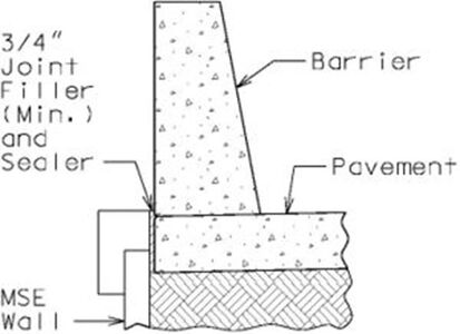 Barrier at Top of MSE Wall
 -

-
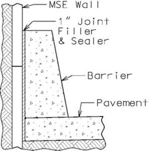 Barrier in Front of MSE Wall


Concrete Cantilever Wall on Spread Footing
Concrete cantilever walls derive their capacity through combinations of dead weight and structural resistance. These walls are constructed of reinforced concrete.
Concrete cantilever walls are used when MSE walls are not a viable option. Cantilever walls can reduce the rock cut required and can also provide solutions when there are right of way restrictions. Concrete walls also provide better structural capacity when barrier or railing on top of the walls are required.
Counterforts are used on rare occasions. Sign-board type retaining walls are a special case of counterfort retaining walls. They are used where the soil conditions are such that the footings must be placed well below the finished ground line. For these situations the wall is discontinued 12 in. below the ground line or below the frost line. Counterforts may also be a cost-savings option when the wall height approaches 20 ft. (Foundation Analysis and Design by Joseph E. Bowles, 4th ed., 1988). However, other factors such as poor soil conditions, slope of the retained soil, wall length and uniformity in wall height should also be considered before using counterforts.
Concrete Cantilever Wall on Pile Footing
Concrete cantilever walls on pile footings are used when the soil conditions do not permit the use of spread footings. These walls are also used when an end bent requires wings longer than 22 feet for seismic category A or 17 ft. for seismic category B, C or D. In these cases a stub wing is left attached to the end bent and the rest of the wing is detached to become a retaining wall as shown in 751.35.3.5 Wing and Detached Wing Walls.
Concrete L-Shaped Retaining Wall on Spread Footings
Concrete L-Shaped walls are cantilever walls without heels. These walls are used when there are space limitations for cantilever walls. Since there is no heel the height of these walls is limited to about 7 ft. depending on the soil conditions and the slope of the retained soil.
L-Shaped Walls are often used next to roadways where the footings are frequently used as shoulders and where the wall will require structural capacity for collision forces.
751.24.1.2 Loads
Conventional retaining walls: Loads shall be determined in accordance with LRFD 3 and 11.6.
MSE retaining walls: Loads shall be determined in accordance with LRFD 3 and 11.10.
Note: For guidance, follow the 751.40.8.15 Cast -In-Place Concrete Retaining Walls and modify guidance of ASD as necessary to meet LRFD requirements until this section is modified for LRFD.
Dead Loads
Dead loads shall be determined from the unit weights in EPG 751.2.1.1 Dead Load.
751.24.2 Mechanically Stabilized Earth (MSE) Walls
751.24.2.1 Design
Designs of Mechanically Stabilized Earth (MSE) walls shall be completed by consultants or contractors in accordance with Section 11.10 of LRFD specifications, FHWA-NHI-10-024 and FHWA-NHI-10-025 for LRFD. Bridge Pre-qualified Products List (BPPL) provided on MoDOT's web page and in Sharepoint contains a listing of facing unit manufacturers, soil reinforcement suppliers, and wall system suppliers which have been approved for use. See Sec 720 and Sec 1010 for additional information. The Geotechnical Section is responsible for checking global stability of permanent MSE wall systems, which should be reported in the Foundation Investigation Geotechnical Report. For MSE wall preliminary information, see EPG 751.1.4.3 MSE Walls. For design requirements of MSE wall systems and temporary shoring (including temporary MSE walls), see EPG 720 Mechanically Stabilized Earth Wall Systems. For staged bridge construction, see EPG 751.1.2.11 Staged Construction.
For seismic design requirements, see Bridge Seismic Design Flowchart. References for consultants and contractors include Section 11.10 of LRFD, FHWA-NHI-10-024 and FHWA-NHI-10-025.
Design Life
- 75 year minimum for permanent walls (if retained foundation require 100 year than consider 100 year minimum design life for wall).
Global stability:
Global stability will be performed by Geotechnical Section or their agent.
MSE wall contractor/designer responsibility:
MSE wall contractor/designer shall perform following analysis in their design for all applicable limit states.
- External Stability
- Limiting Eccentricity
- Sliding
- Factored Bearing Pressure/Stress ≤ Factored Bearing Resistance
- Internal Stability
- Tensile Resistance of Reinforcement
- Pullout Resistance of Reinforcement
- Structural Resistance of Face Elements
- Structural Resistance of Face Element Connections
- Compound Stability
- Capacity/Demand ratio (CDR) for bearing capacity shall be ≥ 1.0
- Strength Limit States:
- Factored bearing resistance = Nominal bearing resistance from Geotech report X Minimum Resistance factor (0.65, Geotech report) LRFD Table 11.5.7-1
- Extreme Event I Limit State:
- Factored bearing resistance = Nominal bearing resistance from Geotech report X Resistance factor
- Resistance factor = 0.9 LRFD 11.8.6.1
- Factored bearing stress shall be computed using a uniform base pressure distribution over an effective width of footing determined in accordance with the provisions of LRFD 10.6.3.1 and 10.6.3.2, 11.10.5.4 and Figure 11.6.3.2-1 for foundation supported on soil or rock.
- B’ = L – 2e
- Where,
- L = Soil reinforcement length (For modular block use B in lieu of L as per LRFD 11.10.2-1)
- B’ = effective width of footing
- e = eccentricity
- Note: When the value of eccentricity e is negative then B´ = L.
- Where,
- Capacity/Demand ratio (CDR) for overturning shall be ≥ 1.0
- Capacity/Demand ratio (CDR) for eccentricity shall be ≥ 1.0
- Capacity/Demand ratio (CDR) for sliding shall be ≥ 1.0 LRFD 11.10.5.3 & 10.6.3.4
- Capacity/Demand ratio (CDR) for internal stability shall be ≥ 1.0
- Eccentricity, (e) Limit for Strength Limit State: LRFD 11.6.3.3 & C11.10.5.4
- For foundations supported on soil or rock, the location of the resultant of the reaction forces shall be within the middle two-thirds of the base width, L or (e ≤ 0.33L).
- Eccentricity, (e) Limit for Strength Limit State: LRFD 11.6.3.3 & C11.10.5.4
- Eccentricity, (e) Limit for Extreme Event I (Seismic): LRFD 11.6.5.1
- For foundations supported on soil or rock, the location of the resultant of the reaction forces shall be within the middle two-thirds of the base width, L or (e ≤ 0.33L) for γEQ = 0.0 and middle eight-tenths of the base width, L or (e ≤ 0.40L) for γEQ = 1.0. For γEQ between 0.0 and 1.0, interpolate e value linearly between 0.33L and 0.40L. For γEQ refer to LRFD 3.4.
- Eccentricity, (e) Limit for Extreme Event I (Seismic): LRFD 11.6.5.1
- Note: Seismic design shall be performed for γEQ = 0.5
- Eccentricity, (e) Limit for Extreme Event II:
- For foundations supported on soil or rock, the location of the resultant of the reaction forces shall be within the middle eight-tenths of the base width, L or (e ≤ 0.40L).
- Eccentricity, (e) Limit for Extreme Event II:
General Guidelines
- Drycast modular block wall (DMBW-MSE) systems are limited to a 10 ft. height in one lift.
- Wetcast modular block wall (WMBW-MSE) systems are limited to a 15 ft. height in one lift.
- For Drycast modular block wall (DMBW-MSE) systems and Wetcast modular block wall (WMBW-MSE) systems, top cap units shall be used and shall be permanently attached by means of a resin anchor system.
- For precast modular panel wall (PMPW-MSE) systems, capstone may be substituted for coping and either shall be permanently attached to wall by panel dowels.
- For precast modular panel wall (PMPW-MSE) systems, form liners are required to produce all panels. Using form liner to produce panel facing is more cost effective than producing flat panels. Standard form liners are specified on the MSE Wall Standard Drawings. Be specific regarding names, types and colors of staining, and names and types of form liner.
- MSE walls shall not be used where exposure to acid water may occur such as in areas of coal mining.
- MSE walls shall not be used where scour is a problem.
- MSE walls with metallic soil reinforcement shall not be used where stray electrical ground currents may occur as would be present near electrical substations.
- No utilities shall be allowed in the reinforced earth if future access to the utilities would require that the reinforcement layers be cut, or if there is a potential for material, which can cause degradation of the soil reinforcement, to leak out of the utilities into the wall backfill, with the exception of storm water drainage.
- All vertical objects shall have at least 4’-6” clear space between back of the wall facing and object for select granular backfill compaction and soil reinforcement skew limit requirements. For piles, see pipe pile spacers guidance.
- The interior angle between two MSE walls should be greater than 70°. However, if unavoidable, then place EPG 751.50 J1.41 note on the design plans.
- Drycast modular block wall (DMBW-MSE) systems and Wetcast modular block wall (WMBW-MSE) systems may be battered up to 1.5 in. per foot. Modular blocks are also known as “segmental blocks”.
- The friction angle used for the computation of horizontal forces within the reinforced soil shall be greater than or equal to 34°.
- For epoxy coated reinforcement requirements, see EPG 751.5.9.2.2 Epoxy Coated Reinforcement Requirements.
- All concrete except facing panels or units shall be CLASS B or B-1.
- The friction angle of the soil to be retained by the reinforced earth shall be listed on the plans as well as the friction angle for the foundation material the wall is to rest on.
- The following requirement shall be considered (from 2009_FHWA-NHI-10-024 MSE wall 132042.pdf, page 200-201) when seismic design is required:
- For seismic design category, SDC C or D (Zones 3 or 4), facing connections in modular block faced walls (MBW) shall use shear resisting devices (shear keys, pin, etc.) between the MBW units and soil reinforcement, and shall not be fully dependent on frictional resistance between the soil reinforcement and facing blocks. For connections partially dependent on friction between the facing blocks and the soil reinforcement, the nominal long-term connection strength Tac, should be reduced to 80 percent of its static value.
- Seismic design category and acceleration coefficients shall be listed on the plans for categories B, C and D. If a seismic analysis is required that shall also be noted on the plans. See EPG 751.50 A1.1 note.
- Plans note (EPG 751.50 J1.1) is required to clearly identify the responsibilities of the wall designer.
- Do not use Drycast modular block wall (DMBW-MSE) systems in the following locations:
- Within the splash zone from snow removal operations (assumed to be 15 feet from the edge of the shoulder).
- Where the blocks will be continuously wetted, such as around sources of water.
- Where blocks will be located behind barrier or other obstacles that will trap salt-laden snow from removal operations.
- Do not use Drycast modular block wall (DMBW-MSE) systems or Wetcast modular block wall (WMBW-MSE) systems in the following locations:
- For structurally critical applications, such as containing necessary fill around structures.
- In tiered wall systems.
- For locations where Drycast modular block wall (DMBW-MSE) systems and Wetcast modular block wall (WMBW-MSE) systems are not desirable, consider coloring agents and/or architectural forms using precast modular panel wall (PMPW-MSE) systems for aesthetic installations.
- For slab drain location near MSE Wall, see EPG 751.10.3.1 Drain Type, Alignment and Spacing and EPG 751.10.3.3 General Requirements for Location of Slab Drains.
- Roadway runoff should be directed away from running along face of MSE walls used as wing walls on bridge structures.
- Drainage:
- Gutter type should be selected at the core team meeting.
- When gutter is required without fencing, use Type A or Type B gutter (for detail, see Std. Plan 609.00).
- When gutter is required with fencing, use Modified Type A or Modified Type B gutter (for detail, see Std. Plan 607.11).
- When fencing is required without gutter, place in tube and grout behind the MSE wall (for detail, see MSE Wall Standard Drawings - MSEW, Fence Post Connection Behind MSE Wall (without gutter).
- Lower backfill longitudinal drainage pipes behind all MSE walls shall be two-6” (Min.) diameter perforated PVC or PE pipe (See Sec 1013) unless larger sizes are required by design which shall be the responsibility of the District Design Division. Show drainage pipe size on plans. Outlet screens and cleanouts should be detailed for any drain pipe (shown on MoDOT MSE wall plans or roadway plans). Lateral non-perforated drain pipes (below leveling pad) are permitted by Standard Specifications and shall be sized by the District Design Division if necessary. Lateral outlet drain pipe sloped at 2% minimum.
- Identify on MSE wall plans or roadway plans drainage pipe point of entry, point of outlet (daylighting), 2% min. drainage slopes in between points to ensure positive flow and additional longitudinal drainage pipes if required to accommodate ground slope changes and lateral drainage pipes if required by design.
- Adjustment in the vertical alignment of the longitudinal drainage pipes from that depicted on the MSE wall standard drawings may be necessary to ensure positive flow out of the drainage system.
- Identify on MSE wall plans or roadway plans the outlet ends of pipes which shall be located to prevent clogging or backflow into the drainage system. Outlet screens and cleanouts should be detailed for any drain pipe.
- For more information on drainage, see Drainage at MSE Walls.
MSE Wall Construction: Pipe Pile Spacers Guidance
For bridges not longer than 200 feet, pipe pile spacers or pile jackets shall be used at pile locations behind mechanically stabilized earth walls at end bents. Corrugated pipe pile spacers are required when the wall is built prior to driving the piles to protect the wall reinforcement when driving pile for the bridge substructure at end bents(s). Pile spacers or pile jackets may be used when the piles are driven before the wall is built. Pipe pile spacers shall have an inside diameter greater than that of the pile and large enough to avoid damage to the pipe when driving the pile. Use EPG 751.50 Standard Detailing Note E1.2a on bridge plans.
For bridges longer than 200 feet, pipe pile spacers are required and the pile spacer shall be oversized to mitigate the effects of bridge thermal movements on the MSE wall. For HP12, HP14, CIP 14” and CIP 16” piles provide 24-inch inside diameter of pile spacer for bridge movement. Minimum pile spacing shall be 5 feet to allow room for compaction of the soil layers. Use EPG 751.50 Standard Detailing Note E1.2b on bridge plans.
The bottom of the pipe pile spacers shall be placed 5 ft. min. below the bottom of the MSE wall leveling pad. The pipe shall be filled with sand or other approved material after the pile is placed and before driving. Pipe pile spacers shall be accurately located and capped for future pile construction.
Alternatively, for bridges shorter than or equal to 200 feet, the contractor shall be given the option of driving the piles before construction of the mechanically stabilized earth wall and placing the soil reinforcement and backfill material around the piling. In lieu of pipe pile spacers contractor may place pile jackets on the portion of the piles that will be in the MSE soil reinforced zone prior to placing the select granular backfill material and soil reinforcement. The contractor shall adequately support the piling to ensure that proper pile alignment is maintained during the wall construction. The contractor’s plan for bracing the pile shall be submitted to the engineer for review.
Piling shall be designed for downdrag (DD) loads due to either method. Oversized pipe pile spacers with sand placed after driving or pile jacket may be considered to mitigate some of the effects of downdrag (DD) loads. Sizing of pipe pile spacers shall account for pile size, thermal movements of the bridge, pile placement plan, and vertical and horizontal placement tolerances.
When rock is anticipated within the 5 feet zone below the MSE wall leveling pad, prebore into rock and prebore holes shall be sufficiently wide to allow for a minimum 10 feet embedment of pile and pipe pile spacer. When top of rock is anticipated within the 5 to 10 feet zone below the MSE wall leveling pad, prebore into rock to achieve a minimum embedment (pile only) of 10 feet below the bottom of leveling pad. Otherwise, the pipe pile spacer requires a minimum 5 feet embedment below the levelling pad. Consideration shall also be given to oversizing the prebore holes in rock to allow for temperature movements at integral end bents.
For bridges not longer than 200 feet, the minimum clearance from the back face of MSE walls to the front face of the end bent beam, also referred to as setback, shall be 4 ft. 6 in. (typ.) unless larger than 18-inch pipe pile spacer required. The 4 ft. 6 in. dimension serves a dual purpose:
- 1) the setback ensures that soil reinforcement is not skewed more than 15° for nut and bolt reinforcement connections to clear an 18-inch inside diameter pipe pile spacers by 6 inches per FHWA-NHI-10-24, Figure 5-17C, while considering vertical and horizontal pile placement tolerances
- 2) the setback helps to reduce the forces imparted on the MSE wall from bridge movements that typically are not accounted for in the wall design and cannot be completely isolated using a pipe pile spacer. Increasing the minimum setback shall be considered when larger diameter pile spacers are required or when other types of soil reinforcement connections are anticipated
For bridges longer than 200 feet, the minimum setback shall be 5 ft. 6 in. based on the use of 24-inch inside diameter of pipe pile spacers.
If interference with soil reinforcement is not a concern and the wall is designed for forces from bridge movement, the following guidance for pipe pile spacers clearance shall be used: pipe pile spacers shall be placed 36 in. clear min. from the back face of MSE wall panels to allow for proper compaction; 12 in. minimum clearance is required between pipe pile spacers and leveling pad and 18 in. minimum clearance is required between leveling pad and pile. For isolated pile (e.g, walls skewed from the bent orientation), the pipe pile spacer may be placed 18 in. clear min. from the back face of MSE wall panels.
MSE Wall Plan and Geometrics
- A plan view shall be drawn showing a baseline or centerline, roadway stations and wall offsets. The plan shall contain enough information to properly locate the wall. The ultimate right of way shall also be shown, unless it is of a significant distance from the wall and will have no effect on the wall design or construction.
- Stations and offsets shall be established between one construction baseline or roadway centerline and a wall control line (baseline). Some wall designs may contain a slight batter, while others are vertical. A wall control line shall be set at the front face of the wall, either along the top or at the base of the wall, whichever is critical to the proposed improvements. For battered walls, in order to allow for batter adjustments of the stepped level pad or variation of the top of the wall, the wall control line (baseline) is to be shown at a fixed elevation. For battered walls, the offset location and elevation of control line shall be indicated. All horizontal breaks in the wall shall be given station-offset points, and walls with curvature shall indicate the station-offsets to the PC and PT of the wall, and the radius, on the plans.
- Any obstacles which could possibly interfere with the soil reinforcement shall be shown. Drainage structures, lighting, or truss pedestals and footings, etc. are to be shown, with station offset to centerline of the obstacle, with obstacle size. Skew angles are shown to indicate the angle between a wall and a pipe or box which runs through the wall.
- Elevations at the top and bottom of the wall shall be shown at 25 ft. intervals and at any break points in the wall.
- Curve data and/or offsets shall be shown at all changes in horizontal alignment. If battered wall systems are used on curved structures, show offsets at 10 ft. (max.) intervals from the baseline.
- Details of any architectural finishes (formliners, concrete coloring, etc.).
- Details of threaded rod connecting the top cap block.
- Estimated quantities, total sq. ft. of mechanically stabilized earth systems.
- Proposed grade and theoretical top of leveling pad elevation shall be shown in constant slope. Slope line shall be adjusted per project. Top of wall or coping elevation and stationing shall be shown in the developed elevation per project. If leveling pad is anticipated to encounter rock, then contact the Geotechnical Section for leveling pad minimum embedment requirements.
MSE Wall Cross Sections
- A typical wall section for general information is shown.
- Additional sections are drawn for any special criteria. The front face of the wall is drawn vertical, regardless of the wall type.
- Any fencing and barrier or railing are shown.
- Barrier if needed are shown on the cross section. Barriers are attached to the roadway or shoulder pavement, not to the MSE wall. Standard barriers are placed along wall faces when traffic has access to the front face of the wall over shoulders of paved areas.
Drainage at MSE Walls
- Drainage Before MSE Wall
- Drainage is not allowed to be discharged within 10 ft. from front of MSE wall in order to protect wall embedment, prevent erosion and foundation undermining, and maintain soil strength and stability.
- Drainage Behind MSE Wall
- Internal (Subsurface) Drainage
- Groundwater and infiltrating surface waters are drained from behind the MSE wall through joints between the face panels or blocks (i.e. wall joints) and two-6 in. (min.) diameter pipes located at the base of the wall and at the basal interface between the reinforced backfill and the retained backfill.
- Excessive subsurface draining can lead to increased risk of backfill erosion/washout through the wall joints and erosion at the bottom of walls and at wall terminal ends. Excessive water build-up caused by inadequate drainage at the bottom of the wall can lead to decreased soil strength and wall instability. Bridge underdrainage (vertical drains at end bents and at approach slabs) can exacerbate the problem.
- Subsurface drainage pipes should be designed and sized appropriately to carry anticipated groundwater, incidental surface run-off that is not collected otherwise including possible effects of drainage created by an unexpected rupture of any roadway drainage conveyance or storage as an example.
- External (Surface) Drainage
- External drainage considerations deal with collecting water that could flow externally over and/or around the wall surface taxing the internal drainage and/or creating external erosion issues. It can also infiltrate the reinforced and retained backfill areas behind the MSE wall.
- Diverting water flow away from the reinforced soil structure is important. Roadway drainage should be collected in accordance with roadway drainage guidelines and bridge deck drainage should be collected similarly.
- Guidance
- ALL MSE WALLS
- 1. Appropriate measures to prevent surface water infiltration into MSE wall backfill should be included in the design and detail layout for all MSE walls and shown on the roadway plans.
- 2. Gutters behind MSE walls are required for flat or positive sloping backfills to prevent concentrated infiltration behind the wall facing regardless of when top of backfill is paved or unpaved. This avoids pocket erosion behind facing and protection of nearest-surface wall connections which are vulnerable to corrosion and deterioration. Drainage swales lined with concrete, paved or precast gutter can be used to collect and discharge surface water to an eventual point away from the wall. If rock is used, use impermeable geotextile under rock and align top of gutter to bottom of rock to drain. (For negative sloping backfills away from top of wall, use of gutters is not required.)
- District Design Division shall verify the size of the two-6 in. (min.) diameter lower perforated MSE wall drain pipes and where piping will daylight at ends of MSE wall or increase the diameters accordingly. This should be part of the preliminary design of the MSE wall. (This shall include when lateral pipes are required and where lateral drain pipes will daylight/discharge).
- BRIDGE ABUTMENTS WITH MSE WALLS
- Areas of concern: bridge deck drainage, approach slab drainage, approach roadway drainage, bridge underdrainage: vertical drains at end bents and approach slab underdrainage, showing drainage details on the roadway and MSE wall plans
- 3. Bridge slab drain design shall be in accordance with EPG 751.10.3 Bridge Deck Drainage – Slab Drains unless as modified below.
- 4. Coordination is required between the Bridge Division and District Design Division on drainage design and details to be shown on the MSE wall and roadway plans.
- 5. Bridge deck, approach slab and roadway drainage shall not be allowed to be discharged to MSE wall backfill area or within 10 feet from front of MSE wall.
- (Recommended) Use of a major bridge approach slab and approach pavement is ideal because bridge deck, approach slab and roadway drainage are directed using curbs and collected in drain basins for discharge that protect MSE wall backfill. For bridges not on a major roadway, consideration should be given to requiring a concrete bridge approach slab and pavement incorporating these same design elements (asphalt is permeable).
- (Less Recommended) Use of conduit and gutters:
- Conduit: Drain away from bridge and bury conduit daylighting to natural ground or roadway drainage ditch at an eventual point beyond the limits of the wall. Use expansion fittings to allow for bridge movement and consider placing conduit to front of MSE wall and discharging more than 10 feet from front of wall or using lower drain pipes to intercept slab drainage conduit running through backfill.
- Conduit and Gutters: Drain away from bridge using conduit and 90° elbow (or 45° bend) for smoothly directing drainage flow into gutters and that may be attached to inside of gutters to continue along downward sloping gutters along back of MSE wall to discharge to sewer or to natural drainage system, or to eventual point beyond the limits of the wall. Allow for independent bridge and wall movements by using expansion fittings where needed. See EPG 751.10.3.1 Type, Alignment and Spacing and EPG 751.10.3.3 General Requirements for Location of Slab Drains.
- 6. Vertical drains at end bents and approach slab underdrainage should be intercepted to drain away from bridge end and MSE wall.
- 7. Discharging deck drainage using many slab drains would seem to reduce the volume of bridge end drainage over MSE walls.
- 8. Drain flumes at bridge abutments with MSE walls do not reduce infiltration at MSE wall backfill areas and are not recommended.
- DISTRICT DESIGN DIVISION MSE WALLS
- Areas of concern: roadway or pavement drainage, MSE wall drainage, showing drainage details on the roadway and MSE wall plans.
- 9. For long MSE walls, where lower perforated drain pipe slope become excessive, non-perforated lateral drain pipes, permitted by Standard Specifications, shall be designed to intercept them and go underneath the concrete leveling pad with a 2% minimum slope. Lateral drain pipes shall daylight/discharge at least 10 ft. from front of MSE wall. Screens should be installed and maintained on drain pipe outlets.
- 10. Roadway and pavement drainage shall not be allowed to be discharged to MSE wall backfill area or within 10 feet from front of MSE wall.
- 11. For district design MSE walls, use roadway or pavement drainage collection pipes to transport and discharge to an eventual point outside the limits of the wall.
- Example: Showing drain pipe details on the MSE wall plans.
-
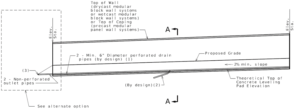 ELEVATION SHOWING DRAIN PIPE
 -
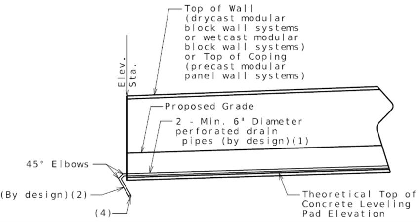 Alternate option


-
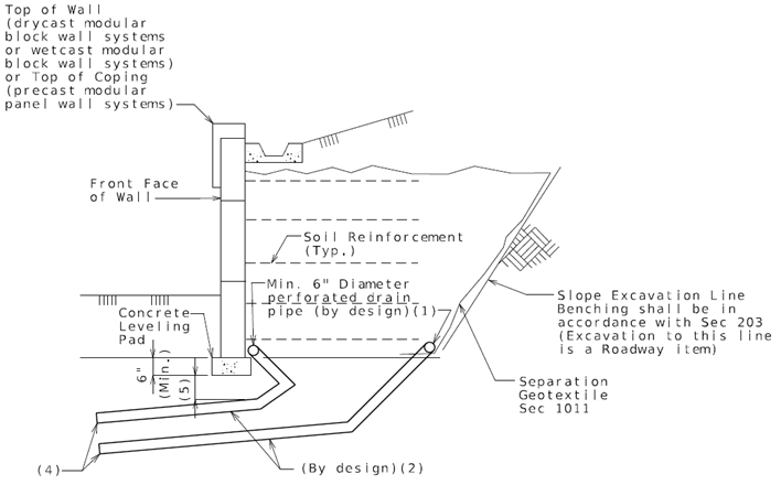 Section A-A

|
Notes: |
751.24.2.2 Excavation
For estimating excavation and minimum soil reinforcement length, see EPG 751.6.2.17 Excavation.
For division responsibilities for preparing MSE wall plans, computing excavation class, quantities and locations, see EPG 747.2.6.2 Mechanically Stabilized Earth (MSE) Wall Systems.
751.24.2.3 Details
| Bridge Standard Drawings |
| MSE Wall - MSEW |
-
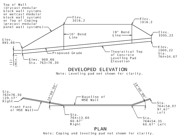 Fig. 751.24.2.3.1 MSE Wall Developed Elevation and Plan

|
(1) Minimum embedment = maximum (2 feet; or embedment based on Geotechnical Report and global stability requirements; |
Drycast Modular Block Wall Systems and Wetcast Modular Block Wall Systems
Battered mechanically stabilized earth wall systems may be used unless the design layout specifically calls for a vertical wall (precast modular panel wall systems shall not be battered and drycast modular block wall systems or wetcast modular block wall systems may be built vertical). If a battered MSE wall system is allowed, then EPG 751.50 J1.19 note shall be placed on the design plans:
For battered walls, note on the plans whether the horizontal offset from the baseline is fixed at the top or bottom of the wall. Horizontal offset and corresponding vertical elevation shall be noted on plans.
-
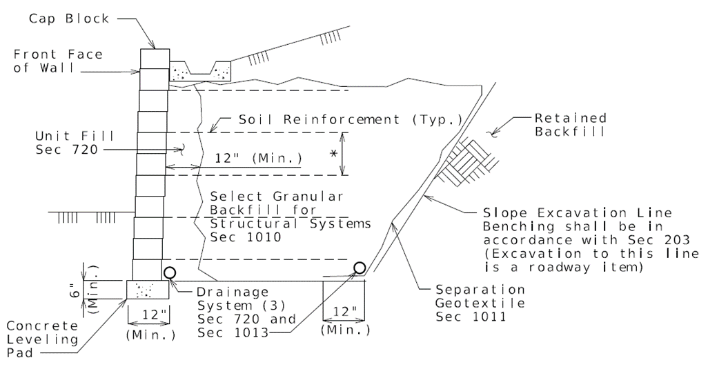 Fig. 751.24.2.3.2 Typical Section Through Generic Drycast Modular Block Wall (DMBW-MSE) System or Wetcast Modular Block Wall (WMBW-MSE) System

|
* The maximum vertical spacing of reinforcement should be limited to two times the block depth or 32 in., whichever is less. |
Fencing (See Bridge Standard Drawing for details)
Fencing may be installed on the Modified Type A or Modified Type B Gutter or behind the MSE Wall.
For Modified Type A and Modified Type B Gutter and Fence Post Connection details, see Standard Plan 607.11.
751.24.3 Cast-In-Place Concrete Retaining Walls
751.24.3.1 Unit Stresses
Concrete Concrete for retaining walls shall be Class B Concrete (f'c = 3000 psi) unless the footing is used as a riding surface in which case Class B-1 Concrete (f'c = 4000 psi) shall be used.
Reinforcing Steel
Reinforcing Steel shall be Grade 60 (fy = 60,000 psi).
Pile Footing
For steel piling material requirements, see the unit stresses in EPG 751.50 A1.3 note.
Spread Footing
For foundation material capacity, see Foundation Investigation Geotechnical Report.
751.24.3.2 Design
Note: For design concepts and guidance, follow the design process (EPG 751.40.8.15) and modify design/details of ASD as necessary to meet LRFD requirements until EPG 751.24 is updated for LRFD.
Capacity/Demand ratio (CDR) for bearing capacity shall be ≥ 1.0
- Strength Limit States:
- Factored bearing resistance = Nominal bearing resistance from Geotech report X
- Minimum Resistance factor (0.55, Geotech report) LRFD Table 11.5.7
- Extreme Event I and II Limit State:
- Factored bearing resistance = Nominal bearing resistance from Geotech report X Resistance factor
- Resistance factor = 0.8 LRFD 11.5.8
- When wall is supported by soil:
- Factored bearing stress per LRFD eq. 11.6.3.2-1
- When wall is supported by a rock foundation:
- Factored bearing stress per LRFD eq. 11.6.3.2-2 and 11.6.3.2-3
- Note: When the value of eccentricity e is negative then use e = 0.
Capacity/Demand ratio (CDR) for overturning shall be ≥ 1.0
Capacity/Demand ratio (CDR) for eccentricity shall be ≥ 1.0
Capacity/Demand ratio (CDR) for sliding shall be ≥ 1.0
- Sliding shall be checked in accordance with LRFD 11.6.3.6 and 10.6.3.4
Eccentricity, (e) Limit for Strength Limit State: LRFD 11.6.3.3
- For foundations supported on soil, the location of the resultant of the reaction forces shall be within the middle two-thirds of the base width, B or (e ≤ 0.33B).
- For foundations supported on rock, the location of the resultant of the reaction forces shall be within the middle nine-tenths of the base width, B or (e ≤ 0.45B).
Eccentricity, (e) Limit for Extreme Event I (Seismic): LRFD 11.6.5.1
- For foundations supported on soil or rock, the location of the resultant of the reaction forces shall be within the middle two-thirds of the base width, B or (e ≤ 0.33B) for γEQ = 0.0 and middle eight-tenths of the base width, B or (e ≤ 0.40B) for γEQ = 1.0. For γEQ between 0.0 and 1.0, interpolate e value linearly between 0.33B and 0.40B. For γEQ refer to LRFD 3.4.
- Note: Seismic design shall be performed for γEQ = 0.5. If live loads act to reduce the eccentricity, then γEQ shall be taken as 0.0.
Eccentricity, (e) Limit for Extreme Event II:
- For foundations supported on soil or/and rock, the location of the resultant of the reaction forces shall be within the middle eight-tenths of the base width, B or (e ≤ 0.40B).
For epoxy coated reinforcement requirements, see EPG 751.5.9.2.2 Epoxy Coated Reinforcement Requirements.
If the height of the wall or fill is a variable dimension, then base the structural design of the wall, toe, and heel on the high quarter point between expansion joints.
