| colspan="2" | For Drilled Shafts and Rock Sockets, see [[751.37 Drilled Shafts#751.37.6.1 Reinforcement Design|EPG 751.37.6.1 Reinforcement Design]].
|-
! colspan="2" | Minimum Pitch - Spiral Reinforcement for Compression Members (Static)
|-
| For Columns, Drilled Shafts, Rock Sockets || See [[751.31_Open_Concrete_Intermediate_Bents#751.31.3.2_Column|EPG 751.31.3.2 Column]]
|-
! colspan="2" | Minimum Spacing- Ties (Transverse) Reinforcement for Compression Members (Static)
|-
| For Columns || See [[751.31_Open_Concrete_Intermediate_Bents#751.31.3.2_Column|EPG 751.31.3.2 Column]]
|-
| For Drilled Shafts and Rock Sockets, see [[751.37 Drilled Shafts#751.37.6.1 Reinforcement Design|EPG 751.37.6.1 Reinforcement Design]]. || 6” centers for #4 bars
|-
! colspan="2" | Maximum Spacing - Longitudinal Compression Reinforcement
|-
| colspan="2" | Absolute Max. - the minimum number of longitudinal reinforcing bars shall be six for circular members and four for bars in a rectangular arrangement. For other requirements, see LRFD
|-
! colspan="2" | Maximum Pitch - Spiral Reinforcement for Compression Members (Static)
|-
| Absolute Max. - Spirals || 6” pitch
|-
! colspan="2" | Maximum Spacing - Ties (Transverse) Reinforcement for Compression Members (Static)
|-
| Absolute Max. - Ties || 12" centers
|-
! colspan="2" | Minimum & Maximum Pitch- Spiral Reinforcement for Compression Members (Seismic)
|-
| colspan="2" | See [[751.9_Bridge_Seismic_Design#751.9.1.2_LRFD_Seismic_Details|EPG 751.9.1.2 LRFD Seismic Details]]
| colspan="3" | Concrete cast against and permanently exposed to earth:
|-
| width=50 | || - primary reinforcement || 3"
|-
| || - stirrups, ties, spirals || 2 1/2"
|-
| colspan="3" | Conc. exposed to earth or weather:
|-
| || - primary reinforcement || 2"
|-
| || - stirrups, ties, spirals || 1 1/2"
|-
| colspan="3" | Conc. slabs which have no positive corrosion protection:
|-
| || - top reinforcement || 3" *
|-
| || - bottom reinforcement || 1"
|-
| colspan="3" | Conc. not exposed to weather or in contact with ground:
|-
| || - primary reinforcement (thru #11) || 1 1/2"
|-
| || - stirrups, ties, spirals || 1"
|-
| colspan="2" | Conc. piles cast against or permanently exposed to earth || 2"
|-
| colspan="3" | '''*''' Absolute minimum cover shall be 2½ inches by LRFD 5.12.3. <br>The minimum cover for stirrup and tie steel shall be 1½ inches unless otherwise specified. <br>For minimum cover for drilled shafts and rock sockets, see [[751.37 Drilled Shafts#751.37.6.1 Reinforcement Design|EPG 751.37.6.1 Reinforcement Design]].
|}
===751.9.1.2 LRFD Seismic Details===
====751.9.1.2.1 Seismic Details for Column Supported on Footing====
| width="35px" | Note: || width="685px" | <sup>1</sup>For simplification use minimum #5 spiral/hoop bar. || width="205px" | SGS 8.8.9
|- style="vertical-align:bottom;"
| || Ro shall be ≥ 0.003 in SDC B and 0.005 in SDC C and D. No need to meet LRFD 5.6.4.6‐1 & 5.11.4.1.4‐1 minimum Ro requirements. || SGS 8.6.5
|-
| || Use 4" spiral pitch/hoop spacing for column to meet long. bar splice area requirements. || LRFD 5.11.4.1.6
|-
| || Use spiral or hoop but combination of spiral reinforcement with hoops shall not be used except in the footing or bent cap. || SGS 8.8.7
|-
| || Closed tie (Hoop) shall use 135‐degree hook with an extension of 6 bar diameters but not less than 3". || SGS 8.8.9
|-
| || Welding of reinforcing steel (spiral, hoop and longitudinal) is not permitted due to the prohibitive cost of weld inspection. ||
|-
| || Spiral does not need to meet end tail requirements of SGS 8.8.7. ||
|-
| || (1) Anchorage of spiral reinforcement shall be provided by 1 1/2 extra turns of spiral reinforcement at end of the spiral unit. ||
|-
| || (2) L<sub>ac</sub> = max(Lac from SGS 8.8.4, 1.25 Ld) or Ldh, but shall be extended to the clear cover specified herein. ||
|-
| || (3) 11 inches for #8 thru #11 bars and 14 inches for #14 bars. ||
|-
| || (4) Plastic hinge area for SDC B: Lpr ≥ max(1.0 * col dia, 1/6 clear col ht., 18") || SGS C8.8.9 & LRFD C5.11.4.1.4
|-
| || (4) Plastic hinge area for SDC C and D: Lpr ≥ max(1.5 * col dia, Lp, 1/6 clear column ht.) || SGS 4.11.6 and 4.11.7
|- style="vertical-align:bottom;"
| || (4) Long reinf. and spiral bar shall not be spliced in plastic hinge area. If splice is unavoidable, a mechanical bar splice shall be used. || SGS 8.8.3 LRFD 5.11.4.1.6
|- style="vertical-align:bottom;"
| || (5) Minimum lap: Use greater of [[751.5_Structural_Detailing_Guidelines#751.5.9.2.8.2_Development_and_Lap_Splices_of_Deformed_Bars_in_Tension|EPG 751.5.9.2.8.2]] Class B lap splice or 60 bar diameters. Lap splices and mechanical bar splices are to be alternately staggered at least 24”at two different locations. || LRFD 5.10.8.4.3b
|-
| || For dowel bar in beam cap, See [[751.22_Prestressed_Concrete_I_Girders#751.22.2.7_Dowel_Bars|EPG 751 .22.2.7 Dowel Bars]] ||
|-
| || For additional requirements of column joints in SDC C and D, See [[751.9_Bridge_Seismic_Design#751.9.1.2.4_T-Joint_(Column_Joint)_Connections_for_Seismic_Design_category_C_and_D|EPG 751 .9.1.2.4 T-Joint (Column Joint) Connections for Seismic Design Category C and D]]. ||
|-
| || Use [[#751.9.1.2.1.1|Figure 751.9.1.2.1.1]] and [[#751.9.1.2.1.2|Figure 751.9.1.2.1.2]] for seismic detail option. For complete seismic design option spiral/hoop bar size shall be increased up to #6 and pitch/spacing shall be reduced as needed by design. Absolute minimum clearance is 1.5 inches. ||
| width="35px" | Note: || width="755px" | <sup>1</sup>For simplification use minimum #5 spiral/hoop bar. || width="220px" | SGS 8.8.9
|- style="vertical-align:bottom;"
| || Ro shall be ≥ 0.003 in SDC B and 0.005 in SDC C and D. No need to meet LRFD 5.6.4.6‐1 & 5.11.4.1.4‐1 minimum Ro requirements. || SGS 8.6.5
|-
| || Closed tie (Hoop) shall use 135‐degree hook with an extension of 6 bar diameters but not less than 3". || SGS 8.8.9
|-
| || Spiral does not need to meet end tail requirements of SGS 8.8.7. ||
|-
| || (6) Anchorage of spiral reinforcement shall be provided by 1 1/2 extra turns of spiral reinforcement at end of the spiral unit. ||
|-
| || (7) Plastic hinge area for SDC B: Lpr ≥ drilled shaft diameter. || SGS C8.8.9 and LRFD C5.11.4.1.4
|-
| || (7) Plastic hinge area for SDC C and D: Lpr ≥ max(1.5 * Column dia., Lp, drilled shaft diameter). || SGS 4.11.6 and 4.11.7
|- style="vertical-align:bottom;"
| || (7,8) Long reinforcement and spiral bar shall not be spliced in plastic hinge area. If splice is unavoidable, a mechanical bar splice shall be used. || SGS 8.8.3 and LRFD 5.11.4.1.6
|-
| || (8) Plastic hinge area : Lpr ≥ drilled shaft diameter. ||
|- style="vertical-align:bottom;"
| || (9) Minimum lap: Use greater of [[751.5_Structural_Detailing_Guidelines#751.5.9.2.8.2_Development_and_Lap_Splices_of_Deformed_Bars_in_Tension|EPG 751.5.9.2.8.2]] Class B lap splice or 60 bar diameters. Lap splices and mechanical bar splices are to be alternately staggered at least 24”at two different locations. || LRFD 5.10.8.4.3b
|- style="vertical-align:bottom;"
| || (10) Use spiral or hoop but combination of spiral reinforcement with hoops shall not be used except in the bent cap. From above table if hoop required for drilled shaft than hoop shall be used in the column and if spiral required for drilled shaft than spiral shall be used in column. Use spiral or hoop bar size and pitch or spacing per [[751.9_Bridge_Seismic_Design#751.9.1.2.1_Seismic_Details_for_Column_Supported_on_Footing|EPG 751.9.1.2.1]] || SGS 8.8.7
|-
| || Welding of reinforcing steel (spiral, hoop and longitudinal) is not permitted due to the prohibitive cost of weld inspection. ||
|-
| || For detail simplification consider drilled shaft 6” larger than column. Avoid sizing shafts 12” larger than column. ||
|-
| || For column and beam detail requirements, see [[751.9_Bridge_Seismic_Design#751.9.1.2.1_Seismic_Details_for_Column_Supported_on_Footing|EPG 751.9.1.2.1]]. ||
|-
| || For oversized shaft (generally 18" minimum larger than column), see [[751.9_Bridge_Seismic_Design#751.9.1.2.3_Seismic_Details_for_Oversized_Drilled_Shaft|EPG 751.9.1.2.3 Seismic Details for Oversized Drilled Shaft]]. ||
|-
| || For additional requirements of column joints in SDC C and D, See [[751.9_Bridge_Seismic_Design#751.9.1.2.4_T-Joint_(Column_Joint)_Connections_for_Seismic_Design_category_C_and_D|EPG 751.9.1.2.4 T-Joint (Column Joint) Connections for Seismic Design Category C and D]]. ||
|-
| || Use [[#751.9.1.2.2|Figure 751.9.1.2.2]] for seismic detail option. For complete seismic design option spiral/hoop bar size shall be increased up to #6 and pitch/spacing shall be 6” by design. Absolute minimum clearance is 5 inches. If #6 at 6” spiral or hoop do not meet design requirements, then use 2-#6 hoop bars @ 8” spacing. ||
|-
| || For seismic bar details (spiral and hoop), see [[#751.9.1.2.1.2|Figure 751.9.1.2.1.2]] ||
| width="35px" | Note: || width="755px" | <sup>1</sup>For simplification use minimum #5 spiral/hoop bar. || width="220px" | SGS 8.8.9
|- style="vertical-align:bottom;"
| || Ro shall be ≥ 0.003 in SDC B and 0.005 in SDC C and D. No need to meet LRFD 5.6.4.6‐1 & 5.11.4.1.4‐1 minimum Ro requirements. || SGS 8.6.5
|-
| || Closed tie (Hoop) shall use 135‐degree hook with an extension of 6 bar diameters but not less than 3". || SGS 8.8.9
|-
| || Spiral does not need to meet end tail requirements of SGS 8.8.7. ||
|-
| || (11) Anchorage of spiral reinforcement shall be provided by 1 1/2 extra turns of spiral reinforcement at end of the spiral unit. ||
|-
| || (12) Plastic hinge area for SDC B: Lpr ≥ drilled shaft diameter. || SGS C8.8.9 and LRFD C5.11.4.1.4
|-
| || (12) Plastic hinge area for SDC C and D: Lpr ≥ max(1.5 * Column dia., Lp, drilled shaft diameter). || SGS 4.11.6 and 4.11.7
|- style="vertical-align:bottom;"
| || (12) Long reinforcement and spiral bar shall not be spliced in plastic hinge area. If splice is unavoidable, a mechanical bar splice shall be used. || SGS 8.8.3 and LRFD 5.11.4.1.6
|-
| || (13) Plastic hinge area : Lpr ≥ drilled shaft diameter. ||
|- style="vertical-align:bottom;"
| || (14) Minimum lap: Use greater of [[751.5_Structural_Detailing_Guidelines#751.5.9.2.8.2_Development_and_Lap_Splices_of_Deformed_Bars_in_Tension|EPG 751.5.9.2.8.2]] Class B lap splice or 60 bar diameters. Lap splices and mechanical bar splices are to be alternately staggered at least 24”at two different locations. || LRFD 5.10.8.4.3b
|-
| || (15) Since column reinforcement embedded into drilled shaft, clear spacing between column reinforcement shall be 5” min. ||
|-
| || (16) Spiral pitch or hoop bar spacing shall be same as drilled shaft requirements. ||
|- style="vertical-align:bottom;"
| || Use spiral or hoop but combination of spiral reinforcement with hoops shall not be used in a reinforcement cage except in bent cap. Spirals in the column cage and hoops in the drilled shaft cage can be used for oversized drilled shaft || SGS 8.8.7
|-
| || Welding of reinforcing steel (spiral, hoop and longitudinal) is not permitted due to the prohibitive cost of weld inspection. ||
|-
| || Hoops are preferred for drilled shafts with diameters at least 2’-6” larger than column. Spirals shall be used in drilled shafts that are oversized by 18” or 24” due to potential interference between the hooks and the column reinforcing cage. ||
|-
| || Column confinement: ||
|-
| || For column use spiral/pitch or hoop/spacing and bar size per column shear reinforcement requirements. ||
|-
| || Drilled shaft confinement: ||
|-
| || Exterior cage: From above table use spiral/pitch or hoop/spacing for drilled shaft. ||
|-
| || Interior cage: Column confinement reinforcement bar size from column shear reinforcement table shall be spaced or<br> pitched same as drilled shaft and provided over entire embedded length of column steel in drilled shaft. ||
|-
| || For column and beam detail requirements, see column shear reinforcement.
|-
| || For additional requirements of column joints in SDC C and D, See [[751.9_Bridge_Seismic_Design#751.9.1.2.4_T-Joint_(Column_Joint)_Connections_for_Seismic_Design_category_C_and_D|EPG 751.9.1.2.4 T-Joint (Column Joint) Connections for Seismic Design Category C and D]]. ||
|-
| || Use [[#751.9.1.2.3|Figure 751.9.1.2.3]] for seismic detail option. For complete seismic design option spiral/hoop bar size shall be increased up to #6 and pitch/spacing shall be 6” by design. Absolute minimum clearance is 5 inches. If #6 at 6” spiral or hoop do not meet design requirements, then use 2-#6 hoop bars @ 8” spacing. ||
|-
| || For seismic bar details (spiral and hoop), see [[#751.9.1.2.1.2|Figure 751.9.1.2.1.2]] ||
File:751.9.1.2.3_01-2025.png|'''Figure 751.9.1.2.3 Seismic Details for Oversized Drilled Shaft'''
</gallery>
====751.9.1.2.4 T-Joint (Column Joint) Connections for Seismic Design category C and D====
Minimum joint reinforcement shall be provided as shown below. Reinforcement marked as “additional” shall not be used to satisfy other load requirements.
=====751.9.1.2.4.1 Bent Cap Joint Shear Reinforcement =====
{|
|-
| width="10px" | 1. || Additional Vertical Stirrups Outside the Joint Region || width="150px" | SGS 8.13.5.1.1
|-
| || <math>{}A\ {jv_0 \atop s\ \ \ } \geq 0.175 A_{st} A_{st} =</math> Total area of column longitudinal reinforcement anchored in the joint = Total area of column longitudinal reinforcement anchored in the joint ||
|-
| || <math>{}A\ {jv_0 \atop s\ \ \ } =</math> Minimum total area of additional vertical stirrups on each side of joint ||
|-
| || Total area of vertical stirrups shall be provided transversely within a distance equal to the column diameter extending from each face of the column as shown in [[#751.9.1.2.4.1a|Figure 751.9.1.2.4.1a]]. For additional vertical stirrups size and spacing limitations, see EPG 751.31.3.1. ||
|-
| 2. || Additional Vertical Stirrups Inside the Joint Region || SGS 8.13.5.1.2
| || <math>A_{st} =</math> Total area of column longitudinal reinforcement anchored in the joint ||
|-
| || <math>{}A\ {jvi \atop s\ \ \ } =</math> Minimum total area of vertical stirrups inside the joint region ||
|-
| || Total area of vertical stirrups spaced evenly over the column inside the joint region as shown in [[#751.9.1.2.4.1a|Figure 751.9.1.2.4.1a]]. For additional vertical stirrups size and spacing limitations, see [[751.31_Open_Concrete_Intermediate_Bents#751.31.3.1_Beam_Cap|EPG 751.31.3.1]]. ||
| || <math>A_{st} =</math> Total area of column longitudinal reinforcement anchored in the joint ||
|-
| || <math>{}A\ {jvi \atop s\ \ \ } =</math> Minimum total area of additional longitudinal reinforcement in top and bottom faces of the cap beam ||
|-
| || The additional longitudinal reinforcement shall be extended at least one column diameter plus development length from face of the column as shown in [[#751.9.1.2.4.1a|Figure 751.9.1.2.4.1a]] ||
|-
| 4. || Horizontal J-Bars || SGS 8.13.5.1.4
|-
| || #4 Horizontal J-bars shall be hooked around the longitudinal reinforcement on each face of the cap beam at every other stirrup inside the joint as shown in [[#751.9.1.2.4.1b|Figure 751.9.1.2.4.1b]].
|-
| colspan="2" | When complete seismic analysis is required per bridge seismic design flowchart, joint shear reinforcement shall be provided in accordance with AASHTO Guide Specifications for LRFD Seismic Bridge Design (SGS). Modify above information and provide additional reinforcement as needed by design. || style="vertical-align:bottom;" | SGS 8.12 and 8.13
File:751.9.1.2.4.1_02-2025.png|'''Figure 751.9.1.2.4.1b Section Showing Column and Beam Cap Reinforcement<br>(SDC C and D only)'''
</gallery>
=====751.9.1.2.4.2 Footing (Spread Footing and Pile Cap Footing) Joint Shear Reinforcement =====
{|
|-
| colspan="3" | For seismic detail option, use following information for spread footing and pile cap footing || width="170px" | SGS 6.4.7
|-
| colspan="3" | Vertical shear reinforcement #5 at about 12” each way shall be placed around the column perimeter within a horizontal dimension from face of the column equal to minimum <math>D_{ftg}</math> as shown in [[#751.9.1.2.4.2a|Figure 751.9.1.2.4.2a]] and [[#751.9.1.2.4.2b|Figure 751.9.1.2.4.2b]]. #6 maximum bar size shall be used for vertical shear reinforcement.
|-
| width="10px" | || width="10px" | <math>D_{ftg}</math> || Effective depth from top of footing to lower reinforcement mat. ||
|-
| colspan="3" | Additional longitudinal horizontal reinforcement at top of footing, <math>A_{sb}</math>: ||
|-
| || <math>A_{sb}</math> || = <math>0.0625 \mbox{ x } A_{st} \mbox{ x } F_{ye} \mbox{/} F_{y}</math> ||
|-
| || colspan="2" | Where, ||
|-
| || <math>A_{st}</math> || = Total area of column longitudinal reinforcement anchored in the joint ||
| || || = 60 ksi for ASTM A706 and ASTM A615 || SGS Table 8.4.2-1
|-
| || || The additional longitudinal reinforcement shall be extended at least up to a distance <math>D_{ftg}</math> plus development length from face of the column and must be placed so that the reinforcement goes through the column reinforcement as shown in [[#751.9.1.2.4.2b|Figure 751.9.1.2.4.2b]] <math>A_{sb}</math> shall be provided in both directions in the footing. ||
|-
| colspan="3" | When complete seismic analysis is required per bridge seismic design flowchart, joint shear reinforcement shall be provided in accordance with AASHTO Guide Specifications for LRFD Seismic Bridge Design (SGS). Modify above information and provide additional reinforcement as needed by design. || style="vertical-align:bottom;" | SGS 6.4.5, 6.4.6 and 6.4.7
For LFD T-Joint connection requirement, see [[751.40_LFD_Widening_and_Repair##751.40.8.11.5_T-_Joint_Connections|EPG 751.40.8.11.5 T- Joint Connections]].
<big><big>'''<font color= red>!!! MOVE TO NEW ARTICLE NUMBER DARREN CHECK THIS SECTION AND MAKE SURE I FOUND AND FIXED ALL THE FIGURE NUMBERS !!!</font color>'''</big></big>
=====751.40.8.11.5 T- Joint Connections=====
'''Principal Tension and Compression Stresses in Beam-Column Joints'''
The connections where columns and beams join, or where columns and footings join, should be based on the capacity design for shear and diagonal tension. For most locations, this is a “T”-shaped joint. For the analysis of “knee joints”, see Priestley and Seible, 1996.
[[image:751.9.3.1.7.1.jpg|center|750px|thumb|<center>'''Fig. 751.40.8.11.5.1 Joint Shear Stresses in a T-Joint'''</center>]]
In the capacity design of connection joints, the column moment, M<sup>0</sup>, will be the moment that is known and which will correspond to flexural overstrength of the column plastic hinges, i.e. M<sup>0</sup> = 1.3M<sub>p</sub> of the column. If the columns are designed based on plastic hinging, the beam and footings shall be designed with capacities greater than or equal to 1.3M<sub>p</sub>.
At each joint, the principal tension and compression stresses are defined and checked as follows:
:V<sub>jh</sub> = Average horizontal shear force within a joint.
:V<sub>jv</sub> = Average vertical shear force within a joint.
:v<sub>jh</sub> = Average horizontal shear stress within a joint.
:v<sub>jv</sub> = Average vertical shear stress within a joint.
:h<sub>b</sub> = Beam depth.
:h<sub>c</sub> = Column diameter or rectangular column cross-section height.
:b<sub>je</sub> = The effective width of a joint, defined in Fig. 751.40.8.11.5.2.
:D = Round column diameter.
:f<sub>v</sub> = Average vertical axial stress due to column axial force P<sub>c</sub>, including the seismic component.
:P<sub>c</sub> = Column axial force.
:f<sub>h</sub> = Average horizontal axial stress at the center of the joint.
:p<sub>c</sub> = Nominal principal compression stress in a joint. (positive)
:p<sub>t</sub> = Nominal principal tensile stress in a joint. (negative)
:b<sub>b</sub> = Beam width
:b<sub>c</sub> = Column cross-section width
[[image:751.9.3.1.7.2.jpg|center|750px|thumb|<center>'''Fig. 751.40.8.11.5.2 Effective Joint Width for Joint Shear Stress Calculations'''</center>]]
In Fig. 751.40.8.11.5.2(c), the effective width is taken at the center of the column section, allowing a 45° spread from boundaries of the column section into the beam cap. In the transverse direction, the effective width will be the smaller of the value given by eq. (3) and the beam cap width b<sub>b</sub>. Experimental evidence indicates that diagonal cracking is initiated in the joint region when <math> p_t \ge 3.5\sqrt{f'_c}</math> psi. The principle compression stress p<sub>c</sub> shall be limited to <math> p_c \le 0.3f'_c</math>.
'''Design of Reinforcement for Beam-Column Joints'''
When the principal tension stress, p<sub>t</sub>, exceeds <math> 3.5\sqrt{f'_c}</math> psi, joint cracking occurs and the following reinforcement shall be provided:
a) Vertical beam stirrup reinforcement shall be placed throughout the distance of h<sub>b</sub>/2 from the column face on each side of the column. The required amount of vertical beam stirrup reinforcement, A<sub>jv</sub>, is:
:where f<sub>yb</sub> = the yield stress of the beam bottom longitudinal reinforcement. This additional reinforcement must be carried a sufficient distance to develop its yield strength a distance h<sub>b</sub>/2 from the column face.
d) The horizontal hoop reinforcement within a joint requires
The spacing of the horizontal hoop can be based on:
<math>S=\frac{4A_s}{D'\rho_s}</math> (15)
:Where
:A<sub>s</sub> = The cross-sectional area of the hoop bar.
:D’ = The hoop diameter.
[[image:751.9.3.1.7.3.jpg|center|725px|thumb|<center>'''Fig. 751.40.8.11.5.3 Beam Cap Joint Reinforcement'''</center>]]
When the principal tension stress, p<sub>t</sub>, does not exceed <math>3.5\sqrt{f'_c}</math> psi, no joint cracking is expected. However, the following minimum reinforcement shall be provided:
:a) Vertical beam stirrup reinforcement within the joint based on eq. (10)
:b) Minimum horizontal hoop reinforcement based on eq. (14)
Note that the bending of any hooked reinforcement outward, away from the column core, shall not be used because it directs the anchorage force away from the joint. Inward bending of the column reinforcement is allowed. However, it is likely to cause a congestion problem. The use of straight column reinforcement embedded into the beam-column joint is recommended. The standard T-joint reinforcement details are shown in Figs. 751.40.8.11.5.4 - 751.40.8.11.5.6. If any reinforcement requirement based on eqs. (9) through (14) is greater than that shown in Figs. 751.40.8.11.5.4 - 751.40.8.11.5.6, the greater requirement shall be used.
<div id="Fig. 751.40.8.11.5.4"></div>
[[image:751.9.3.1.7.4 2019.jpg|center|600px|thumb|<center>'''Fig. 751.40.8.11.5.4 Int. Bent "T-Joint" Details'''</center>]]
::(1) Increase by 25% the development length (other than top bars) or the standard hook in tension “Ldh” of EPG 751.40.8.4.2.
::(2) The spiral bars or wire shall be continued for a distance equal to ½ the column diameter but not less than 15” from the face of the column connection into the footing.
::(3) Use the greatest length of the following: column diameter of 1/6 of the clear height of column. Lapping of spiral reinforcement in this region is not permitted.
::(4) Splices may be eliminated when the column height is 20’-0” or less or restrictions do not practically allow for lap splices.
[[image:751.9.3.1.7.5 2019.jpg|center|750px|thumb|<center>'''Fig. 751.40.8.11.5.5 Seismic Bar Details'''</center>]]
::See additional guidance in EPG 751.9.3.1.7, below, for footing reinforcement not shown.
::(1) Increase by 25% the development length (other than top bars) or the standard hook minimum in tension “Ldh” of EPG 751.40.8.4.2.
::(2) The spirals shall be continued for a distance equal to ½ the column diameter but not less than 15” from the face of the column connection into the footing.
'''Example 751.9.3.1.7.1:''' A column is subjected to an axial load (due to dead and seismic earthquake loads) of 520 kips. The column diameter is 36 in. with 20 #8 bars for longitudinal reinforcement. The beam cap dimensions are 3 ft. 9 in. wide by 3 ft. 7 in. deep with 5 #11 bars for the top reinforcement and 7 #10 bars for the bottom reinforcement as shown in Fig. 751.40.8.11.5.7. The column overstrength moment-axial load curve is shown in Fig. 751.40.8.11.5.8. Design the reinforcement details for the beam-column joint.
[[image:751.9.3.1.7.7.jpg|center|650px|thumb|<center>'''Fig. 751.40.8.11.5.7 Properties for Example Design'''</center>]]
:From eq. (15): <math>S=\frac{4A_s}{D'\rho_s} = \frac{4(0.1963)}{31.5(0.003238)}</math> = 7.70” spacing > 3” max. from Fig. 751.40.8.11.5.4. Therefore, '''Use S = 3”'''
[[image:751.9.3.1.7.9.jpg|center|650px|thumb|<center>'''Fig. 751.40.8.11.5.9 Summary of “T-Joint” Reinforcement'''</center>]]
'''Principal Tension and Compression Stresses in Column-Footing Joints'''
Column – Footing joints are essentially the same as inverted beam-column T joints. Eqs. (1) through (8) are applicable to column-footing joints except the beam height, h<sub>b</sub>, shall be changed to the footing height, h<sub>f</sub>.
'''Design of Reinforcement for Column-Footing Joint'''
The design of the reinforcement for column-footing joints is similar to that for beam-column T joint. From a joint performance viewpoint, it is desirable to bend the column bars inward toward the joint by using 90° hook bars, but this will cause undue congestion. Bending column bars away from the joint will increase the diagonal tension stress within the joint region. However, it makes a stable platform for supporting the column cage and prevents congestion. When the column reinforcement is bent outward, eqs. (9) through (14) shall be applied. Since the column inelastic action may develop in directions other than parallel to one of the principal axes of the footing, the amount of vertical reinforcement in eq. (9) shall be placed in each of the four quadrant areas outside the joint. In other words, a total vertical stirrup area of:
Extra top reinforcement in the footing is also required in accordance with eq. (11). This reinforcement should pass through the column reinforcement or be placed as close as possible to the sides of the column and extend a distance of not less than l = 0.5*D + L<sub>d</sub>, where L<sub>d</sub> is the bar development length, beyond the face on both sides of the column.
'''Example 751.9.3.1.7.2:''' A column is subjected to an axial load (due to dead and seismic loads) of 520 kips. The column diameter is 36 in. with 20 #8 bars for longitudinal reinforcement. All column reinforcement is bent outward into the footing away from the joint. The footing depth is 39 inches. The top and bottom reinforcement for the footing is shown in Fig. 751.40.8.11.5.10, below. Design the reinforcement details for the column-footing joint.
[[image:751.9.3.1.7.10.jpg|center|750px|thumb|<center>'''Fig. 751.40.8.11.5.10 Details of Footing Reinforcement for Example 751.40.8.11.5.2'''</center>]]
'''Solution:'''
[[image:751.9.3.1.7.10 solution.jpg|left|300px]]
The axial load for the column = 520 kips.
From Fig. 751.40.8.11.5.8 in Example 751.9.3.1.7.1, M<sup>0</sup> = 1562.6 k-ft.
:This reinforcement must be developed at a distance h<sub>b</sub>/2 away from the face of the column and must be placed so that the reinforcement goes through the column reinforcement. A<sub>sb</sub> is required in both directions in the footing.
:Note: By adding 3 in. to footing depth in this example problem, the principal tensile stress in the joint would have been less than the maximum allowed tensile stress, thus eliminating the need for the special joint reinforcement other than the minimum required reinforcement. However, the practice of increasing footing depth to eliminate the need for the special joint reinforcement should be limited to increasing the footing depth a maximum of 6 inches.
[[image:751.9.3.1.7.11.jpg|center|700px|thumb|<center>'''Fig. 751.40.8.11.5.11 Summary of Column-Footing Joint Reinforcement'''</center>]]
The elastomeric expansion bearings and fixed bearings for steel girders consist of a sole plate and elastomeric bearing pad. Elastomeric bearings at integral end bents and fixed bearings for prestressed girders at intermediate bents consist of elastomeric bearing pad without a sole plate.
The sole plates are flat or beveled to match the profile grade of the roadway surface along the centerline of the girder. If the profile grade is equal to or less than 0.01 or the total drop across the bearing is equal to or less than 1/8 inch, then a flat sole plate may be used and if necessary, elastomer thickness increased to address the bearing rotation due to the profile grade. Sole plates are used to anchor girders, ensure uniform distribution of the compressive stress and strain over bearing area and reduce dead load bearing rotations.
At fixed bearings, [[#751.11.3.6 Girder/Beam Chairs|girder chairs]] may be considered as an alternate if roadway slope, rotation or bearing pressure is requiring tall or large bearing pads.
The elastomer bearing pad shall be 60 durometer hardness and reinforced with 1/8 inch steel shim plates when laminated pads are required by design.
When rectangular bearings are used, increased rotation bearing capacity can be achieved by orientating the pad with the shorter dimension of the pad parallel with the span of the girder.
<div id="Plain elastomeric bearing pads"></div>
Plain elastomeric bearing pads should be utilized where vertical loads, translations and rotations are relatively small. For integral end bents, use ½” fixed plain pads when taper due to girder slope or grade is less than 1/8”, or use a laminated bearing pad when taper equals or exceeds 1/8” due to girder slope or grade. In the rare circumstance when intermediate bents are made integral by extending the beam cap stirrups into the diaphragm, consideration can be given to utilizing ½” plain pads under similar conditions of slope.
Laminated elastomeric bearing pads should be utilized where there is greater need for vertical loading, translational and rotational capacity. For non-integral end bents, non-integral intermediate bents and for integral end bents when taper exceeds 1/8” due to girder slope or grade use laminated elastomeric bearing pads where the pad thickness and number of laminates is based on design that should account for larger vertical loads, translation, rotation and meet slope of girder and grade requirements.
'''Size Limitations'''
Use the values in the standard bearing pad tables if possible.
Bearing pad length shall be 8” minimum for MoDOT Standard Prestressed (P/S) I-Girders, Adjacent P/S Box Beams and Steel I-Girders.
Bearing pad length shall be 5” minimum for P/S NU Girders and P/S Spread Box Beams. Not preferred but for consideration of some lower bound limits as used by the Nebraska Department of Roads (NDOR) that developed the NU I-Girder, for P/S NU Girders only, and based on NDOR guidelines, a 4” minimum bearing pad length and/or 2 ft. minimum bearing pad width can be used with Structural Project Manager or Structural Liaison Engineer approval.
Laminated Expansion Bearing Pads for PS I-Girders and
Laminated Fixed and Expansion Pads for Steel Girders:
<br/>9” ≤ W ≤ Bottom flange width + 7”
'''Stability'''
The following requirement shall be met for ensuring stability of the bearing pad:
<u>Rectangular Pads</u>
<math>\,h_{rt} \le MIN \big\{L/3, W/3\big\}</math>
<u>Circular Pads</u>
<math>\,h_{rt} \le {D/4}</math>
'''Temperature Movement'''
Determining temperature movements for bearings requires the calculation of the thermal origin of the bridge. To accomplish this, the stiffness of each bent must be calculated. Once the thermal origin is established, the total temperature movement for each bearing location can be found by the following equations:
<math>\,\triangle_s = \gamma \alpha</math> (temperature range)x(distance from thermal origin)(0.65)
Where:
{|
|-
|<math>\,\triangle_s</math> ||= maximum shear deformation of the pad
|-
|<math>\,\gamma</math> ||= 1.2 for laminated pads
|-
| ||= 1.0 for PTFE bearings
|-
|<math>\,\alpha</math>||= coefficient of thermal expansion
|(0.65)||= 65% reduction due to forgiving nature of elastomer (LRFD 14.7.6.3.4)
|}
{|
|-
|temperature range ||= 150ºF (steel superstructure)
|-
| ||= 120ºF (concrete superstructure)
|}
'''Shear Deformation'''
Both plain elastomeric and laminated elastomeric shall meet the following criteria for shear deformation.
<math>\, h_{rt} \ge\ 2 \triangle_s</math>
Where:
<math>\, h_{rt}</math> = total elastomer thickness, in.
The following table represents the available heights of laminated expansion pads that are required due to the shear deformation criteria. PTFE type bearings shall be used if <math>\,\triangle_s >2.5\ in.</math>
|<math>\,\triangle_s</math>, in.||Interior layer thickness, in.||Exterior layer thickness, in.||<math>\,h_{rt}</math>, in.||n||C, in.
|-
|1/2||1/2||1/4||1||2||1 1/4
|-
|3/4||1/2||1/4||1 1/2||3||1 7/8
|-
|1||1/2||1/4||2||4||2 1/2
|-
|1 1/4||1/2||1/4||2 1/2||5||3 1/8
|-
|1 1/2||1/2||1/4||3||6||3 3/4
|-
|1 3/4||1/2||1/4||3 1/2||7||4 3/8
|-
|2||1/2||1/4||4||8||5
|-
|2 1/4||1/2||1/4||4 1/2||9||5 5/8
|-
|2 1/2||1/2||1/4||5||10||6 1/4
|}</center>
Where:
{|
|C ||= total thickness of bearing including steel shims, in.
|-
|n|| = total number of interior layers of elastomer + 1*
|}
'''*''' The additional “1” is accounting for the two exterior layers as per LRFD 14.7.5.3.5
'''Compressive Stress'''
Service loads without including dynamic load allowance shall be used for design checks.
At intermediate bents with 2 bearing pads per girder line (i.e. PS I-girders), use ½ of the live load reaction for each pad.
''Total Load''
Plain Elastomeric Pad
<math>\, \sigma_{TL} \le \ 0.800 ksi</math>
''Laminated Elastomeric Pad''
<math>\, \sigma_{TL} \le 1.00 GS</math>
and
<math>\, \sigma_{TL} \le 1.0 ksi</math>
''Minimum Dead Load''
<math>\, \sigma_{DLmin} \ge 0.200 ksi</math>
The 200 psi minimum requirement is intended for preventing the horizontal crawling of the bearing when it is not attached to the top surface. This requirement has been applied to the bearing designs detailed in EPG 751 even though these bearings are detailed with positive attachment to the flange of the girder. Compliance with the requirement is desirable but is not mandatory if it results in a special bearing design or special superstructure treatments.
Where:
{|
|<math>\,\sigma_{TL}</math>||= compressive stress due to total load = <math>\, \frac{DC + DW + LL} {L \times W}</math>
|-
|<math>\,\sigma_{DLmax}</math>||=compressive stress due to maximum dead load = <math>\, \frac{DC + DW } {L \times W}</math>
|-
|<math>\,\sigma_{DLmin}</math>||=compressive stress due to minimum dead load = <math>\, \frac{DC} {L \times W}</math>
|S ||= shape factor for thickest layer of elastomer = <math>\, \frac{LW}{2h_{ri}(L + W)}</math>
|-
|S ||= shape factor for circular pads = <math>\, \frac{D}{4h_{ri}}</math>
|-
|<math>\,h_{ri}</math> ||= thickness of the i<sup>th</sup> elastomer layer, in.
|}
'''Rotation'''
Rotations shall be taken as the maximum possible change in slope between the top and bottom surfaces of the bearing caused by the initial lack of parallelism between the bottom of girder flange and top of bearing and the girder end rotation due to imposed loads and movements. Rotations may be calculated by a straight-line approximation of dead and live load deflections taken at 1/10 or 1/4 points. The following equation must be satisfied to ensure that uplift does not occur under any combination of loads and corresponding rotation:
|L|| = length of bearing pad in the direction of traffic
|-
|W ||= width of bearing pad in the direction perpendicular to traffic
|-
|G ||= shear modulus = 0.200 ksi for rotation calculations
|-
|<math>\,\theta_s</math> ||= maximum rotation about the transverse axis due to initial lack of parallelism and total service load, rad
|-
|n ||= total number of interior layers of elastomer + 1*
|}
'''*''' The additional “1” is accounting for the two exterior layers as per LRFD 14.7.5.3.5
Plain elastomeric pads contained within integral concrete diaphragms are not subject to this rotation requirement.
This criteria is intended as an uplift check. If uplift is not possible at the bearing due to an integral diaphragm/beam at the abutment or an integral diaphragm/beam at an intermediate bent, then this criteria would not be applicable.
Deflections of elastomeric bearings should be limited to ensure that deck joints and seals are not damaged. Also, bearings that are too flexible can produce a small step across a deck joint giving rise to a high impact loading when traffic passes from one girder to the other. The maximum relative deflection across a joint is suggested to be less than 1/8”.
Initial compressive deflection of plain elastomeric or in any layer of steel reinforced elastomeric bearing at the service limit state without impact shall not exceed <math>\, 0.07 h_{ri}</math>.
Values for compressive strain can be calculated by using LRFD Figure C14.7.6.3.3-1 for 60 durometer reinforced bearings.
There is a code check for compressive deflection of a single layer but no code check for total compressive deflection.
<div id="Taper"></div>
'''Taper'''
When the difference between the slope of the girder and the slope of a bearing pad exceeds 1/8” taper shall be considered. For laminated expansion pads for both PS I-Girders and steel girders and for laminated fixed pads for steel girders where sole plates are required, sole plates shall be tapered to account for the girder slope. Sole plates shall have a minimum thickness of 1 1/2” at the centerline of bearing, and a minimum thickness of 1” at the edge. Plain fixed pads shall not be tapered. At integral end bents where girder slope is greater than 1/8”, use laminated fixed pads. Laminated bearing taper is provided by tapering the top shim to match the slope of the girder to the nearest 1/8” total difference in thickness. Thickness of shims shall be a minimum of 1/8” and a maximum of 1/2”. For excessive girder slopes it may be necessary to taper the top two shims with a maximum combined taper of the bearing of 3/4 inch. Tapered layers of elastomer are not permitted.
[[Image:751.11.2.1 taper.jpg|center|800px]]
<div id="Anchor Bolts"></div>
'''Anchor Bolts'''
Check with Structural Project Manager or Liaison before using anchor bolts other than ASTM F1554. When anchor bolts are used for laminated fixed for steel girders or laminated expansion for steel and P/S I-girders, they should be designed for a minimum horizontal force equal to 25% of the maximum dead load applied to the bearing. With SPM approval for rehab superstructure job designer may design anchor bolt for a minimum horizontal force equal to 15% of the maximum dead load applied to the bearing. Designer may ignore live load in horizontal force computation. Anchor bolts shall be ASTM F1554 Grade 55 unless higher grade anchor bolts are required to meet design requirements. Grade 105 bolts shall not be used in applications where welding to the bolt is required. (Revise anchor bolt notes in [[751.50 Standard Detailing Notes|EPG 751.50 Standard Detailing Notes]] for plans with different grade and nuts, e.g. “ASTM F1554 Grade 55” to “ASTM F1554 Grade 105” and “ASTM A563 Grade A Heavy Hex nuts” to “ASTM A563 Grade DH Heavy Hex nuts”.)
!width="225"|Bolt Type!!width="150"| Nominal Bolt<br/>Diameter (in.)!!width="125"| Min. Tensile<br/>Strength (ksi)!!width="125"| Min. Yield <br/>Strength (ksi)!!width="250"| Comments
|-
|ASTM F1554 (Grade 36)|| ½” to 4”|| 58|| 36||rowspan="3"| Preferred specification for structural supports anchored into concrete.
|-
|ASTM F1554 (Grade 55)|| ½” to 4”|| 75|| 55
|-
|ASTM F1554 (Grade 105)|| ½” to 3”|| 125|| 105
|-
|rowspan="3"|ASTM A449<br/>Type 1<br/>Type 3 (weathering)||¼” to 1”||120||92||Rowspan="2"|Material properties are applicable for old A325 bolts (Pre-2016). May be manufactured as a threaded rod.
|-
| over 1” to 1 ½” ||105|| 81
|-
| 1 ¾” to 3”|| 90|| 58||Typically used for larger diameter headed anchors for bearings in girder shelves.
|-
|ASTM A307|| ¼” to 4”|| 60|| NA||Typically used for regular strength steel connections. Should not be used for applications that require significant tensile or flexural forces on the bolt.
|-
|ASTM F3125 Grade A325<br/>Type 1<br/>Type 3 (weathering)|| ½” to 1 ½”||120|| 92|| Typically used as high strength fasteners, but also used as headed anchors for bearings in girder shelves.
|-
|ASTM F3125 Grade A490<br/>Type 1<br/>Type 3 (weathering)|| ½” to 1 ½”|| 150|| 130|| Typically used as high-strength fastener. Galvanization is not allowed.
|-
|colspan="5" align="left"|Note: The above table is a comprehensive list for bolts typically used in structural applications on MoDOT projects. These values will aid designers when substitutions need to be made for similar design applications.
|}
</center>
Anchor bolts are used on bearings with sole plates. For bridges that require seismic details only, design anchor bolts for flexure and shear induced from horizontal seismic forces and design for tension due to uplift forces if present. For bridges that require a seismic analysis, design anchor bolts for flexure induced from horizontal seismic forces and separately design for the effects of combined tension and shear.
Limit the number of bolts per bearing to four. Concrete Shear blocks shall be used when anchor bolts cannot be designed to resist earthquake loading. For shear blocks details for P/S girder see, [[751.22 Prestressed Concrete I Girders#751.22.3.13 Concrete Shear Blocks|EPG 751.22.3.13 Concrete Shear Blocks]]. Use similar details for shear blocks for steel girder.
Bearing details are shown in [[751.11 Bearings#751.11.3 Details|EPG 751.11.3 Details]] for two 1 ½”, 2” and 2 ½“ diameter anchor bolts. Consult Structural Project Manager before using bolt diameters larger than 2 1/2". Revise bearing details if four anchor bolts are required by design. For larger than 2 ½” diameter anchor bolt revise details in [[751.11 Bearings#751.11.3.5 Anchor Bolts|EPG 751.11.3.5 Anchor Bolts]], bearing details and anchor bolt notes in [[751.50 Standard Detailing Notes|EPG 751.50 Standard Detailing Notes]].
'''For seismic details only (strength limit states)'''
Anchorage shall be adequate to resist lateral loads.
Horizontal factored shear force, <math>{F_H} = \sqrt{(F_T)^2 + (F_L)^2}</math> in kips per girder
For expansion bearings, transverse F<sub>T</sub> = max (A<sub>s</sub>, 0.25)(DL) per girder & longitudinal F<sub>L</sub> = 0.
Where DL = unfactored dead load reaction at the bent, kips
For fixed bearings, transverse F<sub>T</sub> = max (A<sub>s</sub>, 0.25)(DL) per girder and Longitudinal F<sub>L</sub> = max (A<sub>s</sub>, 0.25)(segment weight)/(# of girders)
Segment weight includes the full width of superstructure and should be distributed appropriately among fixed bents.
When centrifugal forces are present, they should be checked independently (not combined with seismic loads shown above or below). Use a 1.75 load factor with the centrifugal force and check resistance at the Strength Limit state as described below.
'''For complete seismic analysis '''
Anchor bolt designs must meet requirements for strength limit states from above as well as seismic forces from seismic analysis. Anchorage shall be adequate to resist lateral loads as well as uplift force from seismic analysis.
F<sub>H</sub> = horizontal seismic force per girder, kips
::If columns are designed for plastic hinging, use the plastic hinging shear.
<math>\sum{V_L}</math> = summation of top of column longitudinal shears at the bent
<math>\sum{V_T}</math> = summation of top of column transverse shears at the bent
N<sub>G</sub> = number of girders at the bent
''At end bents ''
Use the same formula as above, except substitute the abutment shears in place of the top of column shears.
:<math>{P_u} = \frac{F_H}{{n_b}R}</math>
P<sub>u</sub> = horizontal factored shear force per bolt, kips
n<sub>b</sub> = the number of bolts per girder
For intermediate bent, R = 1.0
For end bent, R = 1.0 for seismic category A & B and 0.8 for seismic category C & D.
'''Flexural Resistance '''
Factored flexural stress shall be less than or equal to the nominal flexural resistance. Assume the bolt is restrained from rotation by the sole plate, but free to translate.
M = P<sub>u</sub> x L/2 = maximum moment per bolt, inch-kips
L = moment arm from center of sole plate to top of the beam cap, inches
S = section modulus for the bolt <math>=\frac{\pi D^3}{32}</math>, cubic inches.
D = minimum body diameter, inches. For F1554 bolts use D = 0.92 x nominal bolt diameter. Alternately, the minimum body diameter can be retrieved from ASTM F1554 Table 4. For all other bolt types the nominal bolt diameter may be used because the bolt is unthreaded in the flexural zone and the minimum body diameter is similar to the nominal diameter.
∅<sub>f</sub> = 1.0 resistance factor for seismic details only (strength limit states) and for complete seismic analysis
Yield strength of the anchor bolt, F<sub>Y</sub> = 55 ksi for Grade 55 and F<sub>Y</sub> = 105 ksi for Grade 105
'''Shear Resistance'''
Factored shear force shall be less than or equal to the nominal shear resistance.
:<math>{P_u} \le {\empty_s}{R_n}</math>
where:
∅<sub>s</sub> = 0.75 resistance for seismic details only (strength limit states) and 1.0 for complete seismic analysis
Nominal shear resistance of an F1554 anchor bolt, R<sub>n</sub> = 0.5A<sub>b</sub>F<sub>ub</sub>N<sub>s</sub> LRFD 6.13.2.12-1, C6.13.2.7 and 14.8.3
Note: ASTM F1554 allows the body diameter of the bolt to be reduced to provide an area not less than the stress area of the threaded portion of the bolt. For this reason, there are no differences in calculation for threads beings included or excluded from the shear plane. If another type of bolt is used for any reason the nominal shear resistance should be determined from LRFD Eq. 6.13.2.7-1 or 2.
A<sub>b</sub> <math>= \frac{\pi D^2}{4}</math> = nominal area of the anchor bolt, square inches
F<sub>ub</sub> = minimum tensile strength of the anchor bolt, ksi
: = 75 ksi for Grade 55, 125 ksi for Grade 105
N<sub>s</sub> = number of shear plane per anchor bolt = 1
D = nominal bolt diameter, inches
'''Tensile Resistance'''
Factored tensile force shall be less than or equal to the nominal tensile resistance.
T = the maximum seismic tensile (uplift) force (DL ± EQ) per girder from the seismic analysis, kips. If (DL+EQ) and (DL-EQ) are both compressive, then there is no need to design the bolts for tensile force.
:<math>\frac{T}{{n_b}} \le {\empty_t}{T_n}</math>
Where:
∅<sub>t</sub> = 0.8 resistance factor for seismic details only (strength limit states) and 1.0 for complete seismic analysis
n<sub>b</sub> = the number of bolts per girder
Nominal tensile resistance of the anchor bolt, T<sub>n</sub> = 0.76A<sub>b</sub>F<sub>ub</sub> LRFD 6.13.2.10.2-1 and 14.8.3
:where:
:A<sub>b</sub> = nominal area of the anchor bolt, square inches
:F<sub>ub</sub> = minimum tensile strength of the anchor bolt, ksi
:: = 75 ksi for Grade 55, 125 ksi for Grade 105
'''Combined Tension and Shear Resistance'''
The resistance of anchor bolts for combined tension and shear force shall be determined in accordance with LRFD 6.13.2.11.
If <math>\frac{P_u}{R_n} \le 0.33</math>, then T<sub>n</sub> = 0.76A<sub>b</sub>F<sub>ub</sub> LRFD 6.13.2.11-1
! !! colspan="2"|Total thick. of bearing including steel shims, C in.!! 1 1/4!! 1 7/8!! 2 1/2!! 3 1/8!! 3 3/4!! 4 3/8!! 5!! 5 5/8!! 6 1/4
|-
!Anchor Bolt Type!! No. of Anchor<br/>Bolt!! Nominal dia. of anchor bolt, in.!!colspan="9"| Maximum horizontal factored shear force reaction, F<sub>H</sub>
|valign="top"|'''Notes:'''||align="left" colspan="11"|Calculations were based on 1-1/2" thick sole plate at centerline of bearing.<br/>Flexural resistance calculations were based on minimum body diameter of the anchor bolt.<br/>For centrifugal forces, check anchor bolts for separate load.<br/>For complete seismic analysis case, design anchor bolts as explained above.
::::Dowel bars shall be used for all fixed intermediate bents under prestressed superstructures. Generally, for typical bridges that require seismic details only (strength limit states), shear resistance from shear key is not considered.
Dowel bars connect standard concrete diaphragms and beams on concrete girder bridges (standard fixed diaphragms are those with beam stirrups NOT extending up into the diaphragm). For a calculated seismic vertical reaction or an anticipated foundation settlement resulting in a net tensile reaction, use the development length of dowel bars into beam and into diaphragm based on dowel bar size. If the dowel bars are not exposed to net tension a 15-inch embedment shall be used regardless of bar size. Dowel bars size and spacing shall be determined by shear design of the bars. (Minimum #6 Bars @ 12" cts.). Dowel bars should be designed for a minimum horizontal force equal to 25% of the maximum dead load applied to the bearing. Live load is ignored in horizontal force computation. For seismic design category SDC B, C and D, dowel bars shall develop minimum L<sub>d</sub> into diaphragm but shall not extend into slab and develop minimum L<sub>d</sub> into beam but 3” minimum clear from bottom face of the beam. Dowel bars shall not be hooked to meet development requirements.
:The number of dowels must also fit into the space available on the key:
::min. bar size = #6; max. bar size = #11
::min. spacing = 6"; max. spacing = 12"
::min. end distance = 3"; max. end distance = 6" (≤ half the spacing)
'''For seismic details only (strength limit states)'''
For fixed bearings, Transverse F<sub>T</sub> = max (A<sub>s</sub>, 0.25)(DL) and Longitudinal F<sub>L</sub> = max (A<sub>s</sub>, 0.25)(segment weight) at bent.
:Segment weight includes the full width of superstructure and should be distributed appropriately among fixed bents.
'''For complete seismic analysis '''
Dowel bar designs must meet requirements for strength limit states from above as well as seismic force demand from seismic analysis.
:F<sub>H</sub> = horizontal seismic force per bent, kips
:::If columns are designed for plastic hinging, use the plastic hinging shear.
:∑V<sub>L</sub> = summation of top of column longitudinal shears at the bent
:∑V<sub>T</sub> = summation of top of column transverse shears at the bent
::<math>P_u = \frac{F_H}{n_d}</math>
:P<sub>u</sub> = Horizontal factored shear force per dowel bar, kips
:n<sub>d</sub> = number of dowel bars
'''Shear Resistance'''
Factored shear force shall be less than or equal to the nominal shear resistance.
::''P<sub>u</sub> ≤ ∅<sub>s</sub> x R<sub>n</sub>''
:where:
:∅<sub>s</sub> = 0.75 resistance for seismic details only (strength limit states) and 1.0 for complete seismic analysis
:Nominal shear resistance of the dowel bar, R<sub>n</sub> = 0.625 A<sub>b</sub>F<sub>ub</sub>, kips
::Note: Since there is no reduced areas as seen in bolts and there is no reduction for bolted connection length, use 0.625 instead of 0.5.
:A<sub>b</sub> = <math>\frac {\pi D^3}{4}</math> = area of the dowel bar, square inches
:F<sub>ub</sub> = minimum tensile strength of the dowel bar, ksi
:F<sub>ub</sub> = 80 ksi for Grade 60
:D = diameter of the dowel bar, inch
'''Tensile Resistance'''
Factored tensile force shall be less than or equal to the nominal tensile resistance.
:T = the maximum seismic tensile (uplift) force (DL ± EQ) from the seismic analysis, kips. If (DL+EQ) and (DL-EQ) are both compressive, then there is no need to design the dowel for tensile force.
::<math>\frac{T}{n_d} \le {\empty_t} T_n</math>
:where:
:∅<sub>t</sub>= 0.8 resistance factor for seismic details only (strength limit states) and 1.0 for complete seismic analysis
:n<sub>d</sub> = the number of dowel bars
:Nominal tensile resistance of the dowel bar, T<sub>n</sub> = A<sub>b</sub>F<sub>ub</sub> Kips
::Note: Since there is no pretension or reduced areas as seen for bolts, the 0.76 factor is not warranted.
:A<sub>b</sub> = area of the dowel bar, square inches
:F<sub>ub</sub> = minimum tensile strength of the dowel bar, ksi
:F<sub>ub</sub> = 80 ksi for Grade 60
'''Combined Tension and Shear Resistance'''
The resistance of dowel bars for combined tension and shear force shall be determined in accordance with LRFD 6.13.2.11.
:Note: Since there is no pretension or reduced areas as seen for bolts, the 0.76 factor is not warranted.
:If <math>\frac{P_u}{R_n} \le 0.33</math>, then T<sub>n</sub> = A<sub>b</sub>F<sub>ub</sub>
:A = Length to be determined by the superstructure requirements or the [[751.9_Bridge_Seismic_Design|minimum support length]] required for earthquake criteria, to the
::nearest 1”. Use square ends.
:B = Width to be determined by the minimum of: superstructure requirements, [[751.9_Bridge_Seismic_Design|minimum support length]] required for earthquake criteria, or
::column diameter + 6”. (6” increments) (*)
:C = Depth as required by design. 2’-6” minimum and no less than the column diameter. (3” increments) (*)
:'''*''' For SDC A ratio of beam width to beam depth, B/C, shall be ≤ 1.25. For SDC B, C and D, beam depth shall be proportioned to D ≤ C ≤ 1.25 D. SGS 8.13.5-1
Columns
:D = Column diameter. 2’-6” minimum. Use 3’-0” minimum when the beam depth exceeds 3’-6”. (6” increments)
:D' = Beam width overhang. Controlled by one of the following:
::1) Beam width controlled by superstructure requirements
:::<math>\, \Rightarrow</math> 3” ≤ D' ≤ 6”
::2) Beam width controlled by [[751.9_Bridge_Seismic_Design|minimum support length]] required for earthquake criteria.
:::<math>\, \Rightarrow</math>3” ≤ D' ≤ 15”
:L = Spacing as determined by design, with no limit. (1” increments)
:G = Overhang as determined by design, with no limits.
:H = Column height as required by grade and footing elevations. Use construction joint in column when H exceeds 35’-0”.
:NOTE: Try to keep columns and beams the same size where possible for economy of construction.
===751.31.1.3 Web Beam – Web Supporting Beam===
[[Image:751.31.1.3 2019.jpg|center|450px]]
Beam
:A = Length to be determined by the superstructure requirements or the [[751.9_Bridge_Seismic_Design|minimum support length]] required for earthquake criteria, to the
::nearest 1”. Use square ends.
:B = Width to be determined by the minimum of: superstructure requirements, [[751.9_Bridge_Seismic_Design|minimum support length]] required for earthquake criteria, or
::column diameter + 6”. (6” increments) (*)
:C = Depth as required by design. 2’-6” minimum and no less than the column diameter. (3” increments) (*)
:'''*''' For SDC A ratio of beam width to beam depth, B/C, shall be ≤ 1.25. For SDC B, C and D, beam depth shall be proportioned to D ≤ C ≤ 1.25 D. SGS 8.13.5-1
:D' = Beam width overhang. Controlled by one of the following:
::1) Beam width controlled by superstructure requirements
:::<math>\, \Rightarrow</math> 3” ≤ D' ≤ 6”
::2) Beam width controlled by [[751.9_Bridge_Seismic_Design|minimum support length]] required for earthquake criteria.
:::<math>\, \Rightarrow</math>3” ≤ D' ≤ 15”
:L = Spacing as determined by design, with 35'-0" maximum. (1” increments)
:G = Overhang as determined by design, with no limits.
:H = Column height as required by grade and footing elevations.
Webs
:T = Web thickness. For a 3’-0” column diameter, use T = column diameter. For column diameters ≥ 3’-6”, use T = 0.5 x (column diameter).
:H' = See bottom elevations of web given on the Design Layout.
:NOTE: Try to keep columns and beams the same size where possible for economy of construction.
===751.31.1.4 Tie Beam===
[[Image:751.31.1.4.jpg|center|450px]]
Beam
:A = Length to be determined by the superstructure requirements or the [[751.9_Bridge_Seismic_Design|minimum support length]] required for earthquake criteria, to the
::nearest 1”. Use square ends.
:B = Width to be determined by the minimum of: superstructure requirements, [[751.9_Bridge_Seismic_Design|minimum support length]] required for earthquake criteria, or
::column diameter + 6”. (6” increments) (*)
:C = Depth as required by design. 2’-6” minimum and no less than the column diameter. (3” increments) (*)
:'''*''' For SDC A ratio of beam width to beam depth, B/C, shall be ≤ 1.25. For SDC B, C and D, beam depth shall be proportioned to D ≤ C ≤ 1.25 D. SGS 8.13.5-1
:D' = Beam width overhang. Controlled by one of the following:
::1) Beam width controlled by superstructure requirements
:::<math>\, \Rightarrow</math> 3” ≤ D' ≤ 6”
::2) Beam width controlled by [[751.9_Bridge_Seismic_Design|minimum support length]] required for earthquake criteria.
:::<math>\, \Rightarrow</math>3” ≤ D' ≤ 15”
:L = Spacing as determined by design, with 30'-0" maximum. (1” increments)
:G = Overhang as determined by design, with no limits.
:H = Column height as required by grade and footing elevations.
Tie Beam
:T = Tie beam thickness. Minimum T = 0.5 x (column diameter).
:H' = See bottom elevations of tie beam given on the Design Layout. Minimum H' = 2 x T (round to the next foot higher).
:NOTE: Try to keep columns and beams the same size where possible for economy of construction.
===751.31.1.5 Tie Beam with Change in Column Diameter===
[[Image:751.31.1.5.jpg|center|450px]]
Beam
:A = Length to be determined by the superstructure requirements or the [[751.9_Bridge_Seismic_Design|minimum support length]] required for earthquake criteria, to the
::nearest 1”. Use square ends.
:B = Width to be determined by the minimum of: superstructure requirements, [[751.9_Bridge_Seismic_Design|minimum support length]] required for earthquake criteria, or
::column diameter + 6”. (6” increments) (*)
:C = Depth as required by design. 2’-6” minimum and no less than the column diameter. (3” increments) (*)
:'''*''' For SDC A ratio of beam width to beam depth, B/C, shall be ≤ 1.25. For SDC B, C and D, beam depth shall be proportioned to D1 ≤ C ≤ 1.25 D1. SGS 8.13.5-1
:D2 = Column diameter, Minimum of (D1 + 6”). Check lap of vertical reinforcement required. See Structural Project Manager.
:D' = Beam width overhang. Controlled by one of the following:
::1) Beam width controlled by superstructure requirements
:::<math>\, \Rightarrow</math> 3” ≤ D' ≤ 6”
::2) Beam width controlled by [[751.9_Bridge_Seismic_Design|minimum support length]] required for earthquake criteria.
:::<math>\, \Rightarrow</math>3” ≤ D' ≤ 15”
:L = Spacing as determined by design, with a 30’-0” maximum with tie beams and no limit without tie beams. (1” increments)
:G = Overhang as determined by design, with no limits.
:H = Column height as required by grade and footing elevations.
:H' = Approximately 0.5 x H. Top of tie beam should be at the same elevation as the top of the larger diameter columns in order to
::minimize the number of construction joints. Top of tie beam may be located on the Design Layout.
Tie Beam
:I = Depth as required by design. Minimum of 3’-0” (3” increments).
:J = Width as required by design. Minimum of (0.5 x D1).
:NOTE: Try to keep columns and beams the same size where possible for economy of construction.
===751.31.2.3 General Design Assumptions===
<center>
[[Image:751.31 Open Concrete Int Bents and Piers- General Intermediate Bent Elevation.gif]]
'''*''' Use only if specified on the Design Layout or as stated by the guidelines in this article.
'''**''' For column spacings greater than 30'-0", tie beams are not to be used, unless the web supports the beam.
'''Elevations for General Intermediate Bent'''
</center>
''General''
:The following are general design guidelines for the design of intermediate bents.
:Rigid frame design is to be used for designing Intermediate Bents and Piers.
:The joint between the beam and column, and web or tie beam and column, shall be assumed to be integral for all phases of design and must be analyzed for reinforcement requirements as a “Rigid Frame”.
:The joint between the column and footing is assumed to be “fixed”, unless foundation flexibility needs to be considered as required by the Structural Project Manager.
<div id="Beam"></div>
''Beam''
:Beams shall be designed for vertical loads, including a dynamic load allowance (impact) and components of horizontal forces.
:The gross concrete section, without contribution from reinforcement, shall not rupture under service dead loads. In addition, longitudinal reinforcement shall be distributed to control cracking at the Service-I limit state.
:Fatigue design should not control the size of reinforcement in the beam. LRFD 5.5.3.2 may be ignored for open concrete intermediate bents.
:The minimum reinforcement shall be such that the factored flexural resistance, Mr, is greater than or equal to the lesser of:
:Minimum Tensile Reinforcement
:The amount of tensile reinforcement shall be adequate to develop a factored flexural resistance, M<sub>r</sub>, at least equal to the lesser of either:
::1) M<sub>cr</sub> = cracking moment LRFD Eq. 5.7.3.3.2-1
::2) 1.33 times the factored moment required by the applicable strength load combinations specified in LRFD Table 3.4.1-1.
:Additional reinforcement is required in the sides of the beam. The following table gives adequate steel for both temperature and shrinkage (LRFD 5.10.8), and skin reinforcement (LRFD 5.7.3.4).
|+'''Additional side reinforcement required for reinforced concrete beam caps (per face)'''
|width="300"|Beam Height, H||width="400"|Number – Bar Size
|-
|H ≤ 36”||4 - #6
|-
|36” < H < 54”||5 - #6
|-
|54” ≤ H ≤ 72”||6 - #6
|-
|H > 72”||By Design (LRFD 5.7.3.4)
|-
|}
</center>
''Tie Beam''
:Use a tie beam when specified on the Design Layout or by the Structural Project Manager or when the unsupported height exceeds 30 feet, except as noted
:Do not use tie beams on grade separations.
:Do not use tie beams when column spacing exceeds 30 feet. For this situation, use a minimum column diameter of <math>\, Kl_u / 25 (K = 1.2)</math> in lieu of a tie beam.
:Additional side reinforcement shall be designed for temperature and shrinkage (LRFD 5.10.8), and skin reinforcement (LRFD 5.7.3.4).
''Unsupported Height''
:The unsupported height is the distance from the bottom of the beam to the top of the footing. If the distance from the ground line to the top of footing is <math>\, \ge</math> 10 feet, the unsupported height and the fixed point may be measured from the bottom of the beam to the ground line plus 1/2 the distance from the ground line to the top of the footing.
:For single column intermediate bents, the column shall be considered “fixed” at the top of footing for all conditions.
<div id="Columns"></div>
''Columns''
:Use round columns for all bridges, unless otherwise specified on the Design Layout.
:Tops of column shall be designed for vertical loads with consideration of dynamic load allowance (impact) and maximum components of horizontal forces. Bottom of columns do not require impact forces to be included.
:The minimum area of reinforcement, A<sub>s</sub>, shall be taken as the greater of:
:*<math>\, \frac{0.135A_gf'_c}{f_y}</math>
::::::'''LRFD 5.7.4.2'''
:*<math>\, \ 0.01A_g</math>
:Where:
:<math>\, A_g</math>= gross area of section. (in.²)
:For typical columns with f’<sub>c</sub> = 3 ksi, the 1% of column gross area will control. MoDOT prefers to follow ACI 10.9 and recognize LRFD 5.7.4.2 when it would control. (The minimum area of reinforcement based on LRFD is significantly less than ACI for f’<sub>c</sub> = 3 ksi).
|+'''Maximum Allowable Number of Bars for the Given Bar Sizes'''
|rowspan="2"|Column Diameter||colspan="4"|Maximum Number of Bars
|-
|#8||#9||#10||#11
|-
|2’-6”||18||18||17||15
|-
|3’-0”||22||22||21||18
|-
|3’-6”||26||26||26||22
|-
|4’-0”||30||30||30||25
|-
|4’-6”||34||34||34||29
|-
|5’-0”|| ||38||38||32
|-
|5’-6”|| ||43||42||36
|-
|6’-0”|| ||47||46||40
|-
|}
:Above table is applicable for standard dowel bar arrangments, see [[751.31_Open_Concrete_Intermediate_Bents#751.31.3.2_Column|EPG 751.31.3.2]].
:A preliminary economic analysis should be conducted before determining the number of columns and column spacing. For the analysis, assume the rates for Concrete, Class 1 and Class 2 Excavation, and Piles. Omit reinforcing bars in the cost analysis.
''Column Spacing''
:Columns, with the exception of web supporting beam type bents, shall be spaced, to the nearest 1”, in which balanced positive and negative beam moments are produced. A positive beam moment up to 10% larger than the negative beam moment is acceptable. Strength Limit State Load Combinations shall be used to determine column spacing.
:To estimate centerline-to-centerline spacing for a two column bent, use 72% of the distance from centerline of outside girder to centerline of outside girder. For a three column bent, use 44% of the centerline-to-centerline distance of outside girders.
''Footings''
:Footings shall be designed for vertical loads and maximum normal and parallel components of the horizontal forces.
<center>
[[Image:751.31 Open Concrete Int Bents and Piers- Elevations for Intermediate Bent with Web Beam.gif]]
'''Elevations for Intermediate Bent with Web Beam'''
</center>
'''Web Supporting Beam'''
:In analysis, web beams shall be modeled as plate elements. If the ability to model a web beam as a plate element is unavailable, the following may be considered:
''Simplified Model''
:The web itself is made up of several tie beams (typically 4 tie beams). The moment of inertia of an individual tie beam is equal to the moment of inertia of the web in the bent’s out-of-plane direction divided by the total number of tie beams.
:Any column segment which is connected to the web is treated as a prismatic member with moment of inertia in the bent’s out-of-plane direction <math>\, (I_z)</math> equal to the actual column moment of inertia in that direction, and with the moment of inertia in the bent’s in-plane direction <math>\, (I_y)</math> equal to the total moment of inertia of web in the bent’s in-plane direction divided by the total number of columns plus the moment of inertia of the column itself. The equivalent column diameter is assumed to be <math>\, \Bigg( \frac{64I_y}{\pi} \Bigg)^{0.25} </math>.
<center>
[[Image:751.31 Open Concrete Int Bents and Piers- Section Views for Intermediate Bent with Web Beam.gif]]
'''Section Views for an Intermediate Bent with Web Beam'''
</center>
In the above example, the moment of inertia of the column in the bent’s in-plane and out-of-plane directions can be calculated as:
:Additional side reinforcement shall be designed for temperature and shrinkage (LRFD 5.10.8), and skin reinforcement (LRFD 5.7.3.4).
''Column Spacing''
:Columns shall be spaced so that the negative moment in the beam over the outside columns requires a minimum beam depth of 3.0 FT. No attempt should be made to use a column spacing that produces equal positive and negative beam moments. The negative moment is to be determined at the face of the column (for round columns, check moment at the face of an equivalent area square column).
<center>
[[Image:751.31 Open Concrete Int Bents and Piers- Elevations for Intermediate Bent with Tie Beam.gif]]
'''*''' Use a tie beam if specified on the Design Layout or if the design calls for one.
'''**''' For column spacing > 30’, tie beams are not to be used unless the web supports the beam
'''Elevations for Intermediate Bent with Tie Beam'''
</center>
'''Change in Column Diameter'''
:Use rigid frame design.
:If H’ ≤ 0.5H and no tie beam is used, the design may be done assuming the entire column to have the smaller diameter. This will result in a very small error.
''Columns''
:Use round columns for all bridges, unless otherwise specified on the Design Layout.
:Use two or more columns, as required for the more economical design.
''Column Spacing''
:Column spacing (to the nearest 1”) should be that which produces balanced positive and negative moments. A positive beam moment up to 10% larger than the negative beam moment is acceptable. Strength Limit State Load Combinations shall be used to determine column spacing.
''Reinforcement''
:Reinforcement in the beams, column and tie beams for the moments at the joints shall be based on the moment at the face of the column, beam, or tie beam (equivalent square, based on areas, for round columns).
<center>
[[Image:751.31 Open Concrete Int Bents and Piers- Elevations for Hammer Head Intermediate Bent.gif]]
'''Elevations for Hammer Head Intermediate Bent'''
</center>
'''Hammer Head Type Intermediate Bent'''
:Hammer Head type intermediate bents shall be designed according to the applicable provisions listed under the design assumptions for the General intermediate bent guidelines except as follows:
''Reinforcement''
:Additional side reinforcement shall be designed for temperature and shrinkage (LRFD 5.10.8), and skin reinforcement (LRFD 5.7.3.4).
===751.31.2.4 Column Analysis===
Refer to this article to check slenderness effects in column and the moment magnifier method of column design. See Structural Project Manager for use of P Delta Analysis.
'''Transverse Reinforcement'''
''Seismic Design Category (SDC) A''
:Columns shall be analyzed as “Tied Columns”. Unless excessive reinforcement is required, in which case spirals shall be used.
'''Bi-Axial Bending'''
Use the resultant of longitudinal and transverse moments.
'''Slenderness effects in Columns'''
The slenderness effects shall be considered when:
<math>\, \ l_u \ge \frac {22r}{K}</math>
Where:
<math>\, \ l_u</math> = unsupported length of column
<math>\, \ r</math> = radius of gyration of column cross section
<math>\, \ K</math> = effective length factor
Effects should be investigated by using either the rigorous P-∆ analysis or the Moment Magnifier Method with consideration of bracing and non-bracing effects. Use of the moment magnifier method is limited to members with Kl<sub>u</sub>/r ≤ 100, or the diameter of a round column must be ≥ Kl<sub>u</sub>/25. A maximum value of 2.5 for moment magnifier is desirable for efficiency of design. Increase column diameter to reduce the magnifier, if necessary.
When a compression member is subjected to bending in both principal directions, the effects of slenderness should be considered in each direction independently. Instead of calculating two moment magnifiers, db and ds, and performing two analyses for M<sub>2b</sub> and M<sub>2s</sub> as described in LRFD 4.5.3.2.2b, the following conservative, simplified moment magnification method in which only a moment magnifier due to sidesway, δ<sub>s</sub>, analysis is required:
<center>
[[Image:751.31 Open Concrete Int Bents and Piers- Typical Intermediate Bent.gif]]
</center>
<center>'''Typical Intermediate Bent'''</center>
''General Procedure for Bending in a Principal Direction''
::M<sub>c</sub> = δ<sub>s</sub>M<sub>2</sub>
::Where:
::M<sub>c</sub> = Magnified column moment about the axis under investigation.
::M<sub>2</sub> = value of larger column moment about the axis under investigation due to LRFD Load Combinations.
::δ<sub>s</sub> = moment magnification factor for sidesway about the axis under investigation
<math>\, \ K</math> = effective length factor = 1.2 min. (see the following figure showing boundary conditions for columns)
<math>\, \ l_u</math> = unsupported lenth of column (in.)
<math>\, \ EI = \cfrac{{E_cI_g}{/2.5}}{1+\beta_d}</math>
Where:
<math>\, \ E_c</math>= concrete modulus of elasticity as defined in [[751.31 Open Concrete Intermediate Bents#751.31.1.1 Material Properties|EPG 751.31.1.1]] (ksi)
<math>\, \ I_g</math>= moment of inertia of gross concrete section about the axis under investigation <math>\, (in^4)</math>
<math>\, \beta_d</math>= ratio of maximum factored permanent load moments to maximum factored total load moment: always positive
''Column Moment Parallel to Bent In-Plane Direction''
<math>M_{cy}= \delta_{sy}M_{2y}</math>
<math>l_{uy}</math>= top of footing to top of beam cap
''Column Moment Normal to Bent In-Plane Direction''
<math>M_{cz}= \delta_{sz}M_{2z}</math>
<math>l_{uz}</math> = top of footing to bottom of beam cap or tie beam and/or top of tie beam to bottom of beam cap
<center>
{|
|-
|Out-of-plane bending<br>Non-integral Bent||[[Image:751.31 Open Concrete Int Bents and Piers- Boundary Conditions for columns-Top Image.gif]]||Out-of-plane bending<br>Integral Bent
|-
|In-plane bending||[[Image:751.31 Open Concrete Int Bents and Piers- Boundary Conditions for columns-Bottom Image.gif]]||
|-
|}
'''Boundary Conditions for Columns'''
For telescoping columns, the equivalent moment of inertia, <i>I</i>, and equivalent effective length factor, <i>K</i>, can be estimated as follows:
[[Image:751.31 Open Concrete Int Bents and Piers- Telescoping Columns.gif]]
'''Telescoping Columns'''
</center>
<math>\, \ I = \frac {\sum \left(l_n I_n \right)}{L}</math>
Where:
<math>\, l_n</math>= length of column segment <math>\, n</math>
<math>\, I_n</math>= moment of inertia of column segment <math>\, n</math>
<math>\, L</math>= total length of telescoping column
'''Equivalent Effective Length Factor'''
<math>\, \ K =\sqrt \frac{\pi^2EI}{P_cL^2}</math>
Where:
<math>\, E</math> = modulus of elasticity of column
<math>\, I</math> = equivalent moment of inertia of column
<math>\,L</math> = total length of telescoping column
<math>\, P_c</math> =elastic buckling load solved from the equations given by the following boundary conditions:
<center>
''Fixed- Fixed Condition''
[[Image:751.31 Open Concrete Int Bents and Piers- Columns Fixed-Fixed Condition.gif]]
|colspan="2"|<math>\, a_1, a_2, b_1, b_2, c_1, c_2, d_1,</math> and <math>\, d_2</math> are defined in the previous equations.
==751.31.3 Reinforcement==
For Seismic detail requirements for seismic design category, SDC B, C and D, See [[751.9_Bridge_Seismic_Design#751.9.1.2_LRFD_Seismic_Details|EPG 751.9.1.2 LRFD Seismic Details]].
| colspan="2" | '''MINIMUM SPACING AT LAP SPLICES''' || '''ALTERNATE DOWEL PLACEMENT'''
|-
| style="width:25px; text-align:right;" | * || colspan="2" style="text-align:left;" | Use alternate detail only with approval of Structural Project Manager and then design column reinforcement using the smaller ring diameter.
|-
| style="width:25px; text-align:right;" | || colspan="2" style="text-align:left;" | Include 1/2-inch buffer for mechanical bar splice.
| style="width:25px; text-align:right;" | B = || colspan="2" style="text-align:left;" | 2” (2 1/2") clear spacing for bar sizes thru #10.
|-
| style="width:25px; text-align:right;" | || colspan="2" style="text-align:left;" | 2 1/2” (3") clear spacing for bar sizes #11 and #14.
|-
| style="width:25px; text-align:right;" | || colspan="2" style="text-align:left;" | 3 1/2” (4") clear spacing for bar size #18.
|-
| colspan="3" | [[image:751.31.3.2_03-2025.png|center|250px]]
|-
| colspan="3" | '''STIRRUP LAP DETAIL AND STAGGER NOTE'''
|-
| colspan="3" | * X” Minimum lap (Stagger adjacent bar splices)
|-
| colspan="3" style="text-align:left;" | Lap splices for closed circular ties shall be provided and staggered in accordance with LRFD 5.10.6.3.
|-
| colspan="3" style="text-align:left;" | Lap length of 1.3 '''l'''<sub>d</sub> (or Class B) for closed stirrup/ties shall be provided in accordance with LRFD 5.11.2.6.4.
|-
| colspan="3" style="text-align:left;" | Lap length for #4 stirrup bars (4” min. spacing, f’c = 3 ksi, and clear cover = 1½”) equals 24” for uncoated<br>bars and 28” for epoxy coated bars.
|-
| colspan="3" style="text-align:left;" | For lap length for other scenarios, see [[751.5 Structural Detailing Guidelines#751.5.9.2.8 Development and Lap Splices|EPG 751.5.9.2.8 Development and Lap Splices]].
'''<sup>1</sup>''' See [[751.2 Loads#751.2.2.6 Other Loads|EPG 751.2.2.6 Other Loads]] to determine if a pier requires design for collision loads.<br/>
'''<sup>2</sup>''' Design assumptions:<br/>
* Vu = 600 k, Pu = 0 k, Mu = 0 k-ft<br/>
* f’c = 3 ksi, fy = 60 ksi, 1.5” clear cover<br/>
* Shear resistance factor = 1.0<br/>
* Minimum longitudinal reinforcement per [[#751.31.2.3 General Design Assumptions|EPG 751.31.2.3 General Design Assumptions]]<br/>
'''<sup>3</sup>''' The shear reinforcement tabulated is adequate for collision but may not be adequate for other design<br>checks. For example, columns greater than 5’-0” require more stirrups to meet min reinforcement. Lesser<br>reinforcement values may be used by design. Design is required for 3’-0” and 3’-6” columns because the<br>design criteria used for the table requires double stirrups which is not common practice.
|}
::Columns shall be reinforced using stirrup ties, unless excessive reinforcement is required, in which case spirals shall be used.
::Show spiral details of [[751.9_Bridge_Seismic_Design#751.9.1.2.1.1|Fig. 751.9.1.2.1.1]] on the bridge plans if spirals are used for bridge in non-seismic area. Anchorage of spiral reinforcement shall be provided by 1 ½ extra turns of spiral reinforcement at each end of the spiral unit.
::For Seismic detail requirements for seismic design category, SDC B, C and D, See [[751.9_Bridge_Seismic_Design#751.9.1.2_LRFD_Seismic_Details|EPG 751.9.1.2 LRFD Seismic Details]].
{| style="margin: 1em auto 1em auto"
|-
|[[Image:751.31.3.2.3 part elev.jpg|left|375px]]||valign="center"|(1) Location 2 development length.<br/><br/>(2) Check clearance to concrete piles.<br/><br/>See [https://epg.modot.org/index.php/751.5_Structural_Detailing_Guidelines#751.5.9.2.8_Development_and_Lap_Splices EPG 751.5.9.2.8] for development and lap splice lengths not given or lengths for scenarios other than those shown. Provide standard hooks if required.<br/><br/>See [https://epg.modot.org/index.php/751.5_Structural_Detailing_Guidelines#751.5.9.2.2_Epoxy_Coated_Reinforcement_Requirements EPG 751.5.9.2.2] for epoxy coated reinforcement requirements.
|}
===751.37.1.6 Drilled Shaft General Detail Considerations===
For Seismic detail requirements for seismic design category, SDC B, C and D, See [[751.9_Bridge_Seismic_Design#751.9.1.2_LRFD_Seismic_Details|EPG 751.9.1.2 LRFD Seismic Details]].
[[image:751.37.1.6 01.png|700px|center]]
Pay items shown in above table are for example only, show actual pay items and quantities in plan details for specific project.
''Notes:''
::(1) Number of pipes (equally spaced) for Sonic Logging Testing:
::::::Diameter ≤ 2.5 ft: 2 pipes
::::::Diameter >2.5 ft but ≤ 3.5 ft: 3 pipes
::::::Diameter >3.5 ft but ≤ 5.0 ft: 4 pipes
::::::Diameter >5.0 ft but ≤ 8.0 ft: 5 pipes
::::::Diameter >8.0 ft: 6 pipes
::::Single diameter reinforcing cage is typically used. Modify details based on design for single or multiple-diameter cages and splice location(s).
::::See [[#751.37.1.3 Casing|EPG 751.37.1.3]] for casing requirements and alternatives.
::::When determining P bar diameter for barbill, assume 3/8” casing unless otherwise specified.
::::See [[751.50 Standard Detailing Notes#G8. Drilled Shaft|EPG 751.50, G8]], for notes to include for drilled shafts and rock sockets (starting at G8.1).
::(2) See [[#751.37.1.1 Dimensions and Nomenclature|EPG 751.37.1.1 Dimensions and Nomenclature]] for [https://epg.modot.org/forms/general_files/BR/751.37.1.1_Drilled_Shaft_Design_Aid.docx Design Aid: Minimum Rock Socket Length].
::(3) When difference between drilled shaft and column diameter is 6" a single reinforcement cage is typically used for the socket and shaft and the vertical reinforcement extends into the column. A separate column steel cage is then placed around the protruding shaft reinforcement without requiring an adjustment to minimum cover for rock socket or column reinforcement. When difference between drilled shaft and column diameter is 12” either the vertical column steel or dowels will need to be extended into the shaft or the cover in the socket and shaft will need to be increased to allow the shaft reinforcement to extend into the column. In the former scenario an optional construction joint is recommended as discussed in note 4 for oversized shafts. In the latter scenario the same number of vertical bars should be used in the shaft and column to allow the shaft bars to be tied to the column cage. Any reduction in cage diameter required for fit-up shall be considered in design.
::(4) When difference between drilled shaft and column diameter is greater than 12" (oversized shaft generally 18" to 24" larger than column), show "Optional construction joint" at bottom of column/dowel reinforcement in the drilled shaft and use [[751.50_Standard_Detailing_Notes#G8._Drilled_Shaft|EPG 751.50 Standard Detailing Notes G8.8 and G8.9]] in plan details.
<center>
{| border="1" class="wikitable" style="margin: 1em auto 1em auto" style="text-align:center"
|+
| style="background:#BEBEBE" width="400" |'''[https://www.modot.org/bridge-standard-drawings Bridge Standard Drawings]'''</br> (Drilled Shafts - DSS → As Built Drilled Shaft Data [DSS_01])
|-
|align="center"|[https://www.modot.org/media/14725 As Built Drilled Shaft Data (PDF)]
|}
</center>
===751.37.6.1 Reinforcement Design===
Drilled shaft structural resistance shall be designed similarly to reinforced concrete columns. The Strength Limit State and applicable Extreme Event Limit State load combinations shall be used in the reinforcement design.
Longitudinal reinforcing steel shall extend below the point of fixity of the drilled shaft at least 10 ft. in accordance with LRFD 10.8.3.9.3 or the required bar development length whichever is larger.
If permanent casing is used, and the shell consists of smooth pipe greater than 0.12 in. thick, it may be considered load carrying. An 1/8" shall be subtracted off of the shell thickness to account for corrosion. Casing could also be corrugated metal pipe. If casing is assumed to contribute to the structural resistance, the plans should indicate the minimum thickness and type of casing required.
Minimum clear spacing between longitudinal bars as well as between transverse bars shall not be less than five times the maximum aggregate size or 5 in. (LRFD 10.8.3.9.3).
For minimum concrete cover for drilled shaft, see [https://www.modot.org/missouri-standard-specifications-highway-construction Sec 701.4.12.1]. If drilled shaft diameter does not match Sec 701.4.12.1 then use concrete cover for the next greater diameter drilled shaft. For rock sockets use 3” min. clear cover.
For longitudinal reinforcement, splicing shall be in accordance with LRFD 5.10.8.4.
For transverse reinforcement, lap splices for closed circular stirrups/ties shall be provided and staggered in accordance with LRFD 5.10.4.3. Lap length of 1.3 '''l'''<sub>d</sub> (Class B) for closed stirrups/ties shall be provided in accordance with LRFD 5.10.8.2.6d.
For lap length, see [[751.5 Structural Detailing Guidelines#751.5.9.2.8.1 Development and Lap Splice General|EPG 751.5.9.2.8.1 Development and Lap Splice General]].
===751.37.6.2 Longitudinal Reinforcement===
Longitudinal reinforcement shall be designed to resist bending in the shaft due to lateral loads. The cross-sectional area for longitudinal reinforcement shall fall within the following limits:
{| style="margin: 1em auto 1em auto" width="800"
|-
| align="left" rowspan="2" | <math>\frac{0.135 A_g f^'_c}{f_y} \le A_{steel} \le 0.04 A_g</math> || align="center" | (Consistent units of stress)||align="right"|Equation 751.37.6.1
|-
| align="center" | '''LRFD 5.7.4.2 and SGS 8.8.1''' ||
|}
where:
:''A<sub>g</sub>'' = gross cross-sectional area of drilled shaft (consistent units of area),
:''f'<sub>c</sub>'' = concrete compressive strength (consistent units of stress),
:''f<sub>y</sub>'' = yield strength of steel reinforcement (consistent units of stress) and
:''A<sub>steel</sub>'' = cross-sectional area of longitudinal steel reinforcement (consistent units of area).
MoDOT prefers to follow LRFD 5.7.4.2 for drilled shafts since for typical cases, the potential exists for load transfer between the concrete and steel casing. (The minimum area of reinforcement based on LRFD is 10 percent less than ACI for f’<sub>c</sub> = 4 ksi).
===751.37.6.4 Transverse Reinforcement===
Minimum transverse reinforcement shall be designed to resist the potential of diagonal cracking and improve ductility, and to control the stability of the reinforcement cage. Follow the four-step procedure, below for seismic design category SDC A.
For Seismic detail requirements for seismic design category, SDC B, C and D, See [[751.9_Bridge_Seismic_Design#751.9.1.2_LRFD_Seismic_Details|EPG 751.9.1.2 LRFD Seismic Details]].
'''No. 1. Determine if Transverse Reinforcement is Required for Loading'''
:If
{| style="margin: 1em auto 1em auto" width="900"
|-
|align="left"|<math>V_u > 0.5 \boldsymbol\phi V_c</math>,||align="left|then go to No. 2a, below,<br/>otherwise, go to No. 2b.|| align="center"| (consistent units of force) '''(LRFD 5.8.2.4)'''||align="right"|Equation 751.37.6.4.1
|}
:where:
::''V<sub>u</sub>'' = factored shear force (consistent units of force),
::<math>V_c = 0.0316\beta \sqrt{f^'_c} b_v d_v</math> = approximate shear resistance of drilled shaft (consistent units of force),
::''Φ'' = 0.9 = resistance factor for shear resistance of drilled shaft (dimensionless),
::''β'' = 2.0,
::''b<sub>v</sub>'' = D = shaft diameter (consistent units of length),
::''d<sub>v</sub>'' = 0.9 (''D''/2 + ''D<sub>r</sub>'' /π) and
::''D<sub>r</sub>'' = diameter of circle passing through the centers of the longitudinal reinforcement (consistent units of length). See commentary for LRFD C5.8.2.9-2.
:'''a)''' Minimum transverse reinforcement to control shear diagonal cracking and increase ductility:
:The minimum amount of transverse reinforcement shall satisfy the following equation if transverse reinforcement is required for loading in No. 1, otherwise go to No. 2b:
:''A<sub>v</sub>'' = area of transverse reinforcement within distance s (consistent units of area),
:''s'' = spacing of transverse reinforcement (consistent units of length),
:''b<sub>v</sub>'' = ''D'' = shaft diameter (consistent units of length),
:''f'<sub>c</sub>'' = concrete compressive strength (consistent units of stress) and
:''f<sub>y</sub>'' = yield strength of steel reinforcement (consistent units of stress).
:'''b)''' Minimum transverse reinforcement to control stability of cage before and during placement:
:Use minimum #4 @ 12” stirrups for reinforcing cage ≤ 4 ft. diameter and minimum #5 @ 12” stirrups for reinforcing cage > 4 ft. diameter (FHWA-NHI-10-016) unless transverse reinforcement needs to be designed as in No. 1. If transverse reinforcement needs to be designed as in No. 1, then provide the controlling transverse reinforcement area required by EPG 751.37.6.4 No. 2a, 2b and [[#751.37.6.5 Factored Shear Resistance|EPG 751.37.6.5 Factored Shear Resistance]].
:All shafts, cased or uncased, or where casing is used for strength, shall be transversely reinforced.
'''No. 3. Determine Maximum Transverse Reinforcement Spacing:'''
:The maximum transverse reinforcement spacing shall be ≤ 12” to provide crack control without consideration for casing. MoDOT does not implement LRFD 5.8.2.7 maximum spacing of transverse reinforcement requirements for typical shaft sizes. However, for small shafts where LRFD 5.8.2.7 will control, it should be directly implemented.
<div id="No. 4. Determine Maximum"></div>
'''No. 4. Determine Maximum Transverse Shaft Reinforcement Spacing at the Anchorage of Column Reinforcement: '''
:For columns with longitudinal reinforcement anchored into oversized shafts, in the anchorage region, the spacing of the transverse shaft reinforcement shall meet the requirements of the following equation:
| colspan="2" style="text-align:left" | '''*''' Footing depths > 36 in. may require the side faces to have shrinkage and temperature reinforcement. See Structural Project Manager.
| colspan="2" style="text-align:left" | '''*''' Use same area of steel in the top of the footing as is required for the bottom.
|-
| colspan="2" style="text-align:left" | For spread footing joint shear reinforcement requirement for SDC C and D, see [[751.9_Bridge_Seismic_Design#751.9.1.2.4.2_Footing_(Spread_Footing_and_Pile_Cap_Footing)_Joint_Shear_Reinforcement|EPG 751.9.1.2.4.2 Footing (Spread Footing and Pile Cap Footing) Joint Shear Reinforcement]].
Designs of Mechanically Stabilized Earth (MSE) walls shall be completed by consultants or contractors in accordance with Section 11.10 of LRFD specifications, FHWA-NHI-10-024 and FHWA-NHI-10-025 for LRFD. Bridge Pre-qualified Products List (BPPL) provided on MoDOT's web page and in Sharepoint contains a listing of facing unit manufacturers, soil reinforcement suppliers, and wall system suppliers which have been approved for use. See Sec 720 and Sec 1010 for additional information. The Geotechnical Section is responsible for checking global stability of permanent MSE wall systems, which should be reported in the Foundation Investigation Geotechnical Report. For MSE wall preliminary information, see EPG 751.1.4.3 MSE Walls. For design requirements of MSE wall systems and temporary shoring (including temporary MSE walls), see EPG 720 Mechanically Stabilized Earth Wall Systems. For staged bridge construction, see EPG 751.1.2.11 Staged Construction.
For seismic design requirements, see Bridge Seismic Design Flowchart. References for consultants and contractors include Section 11.10 of LRFD, FHWA-NHI-10-024 and FHWA-NHI-10-025.
Design Life
75 year minimum for permanent walls (if retained foundation require 100 year than consider 100 year minimum design life for wall).
Global stability:
Global stability will be performed by Geotechnical Section or their agent.
MSE wall contractor/designer responsibility:
MSE wall contractor/designer shall perform following analysis in their design for all applicable limit states.
Capacity/Demand ratio (CDR) for bearing capacity shall be ≥ 1.0
Strength Limit States:
Factored bearing resistance = Nominal bearing resistance from Geotech report X Minimum Resistance factor (0.65, Geotech report) LRFD Table 11.5.7-1
Extreme Event I Limit State:
Factored bearing resistance = Nominal bearing resistance from Geotech report X Resistance factor
Resistance factor = 0.9 LRFD 11.8.6.1
Factored bearing stress shall be computed using a uniform base pressure distribution over an effective width of footing determined in accordance with the provisions of LRFD 10.6.3.1 and 10.6.3.2, 11.10.5.4 and Figure 11.6.3.2-1 for foundation supported on soil or rock.
B’ = L – 2e
Where,
L = Soil reinforcement length (For modular block use B in lieu of L as per LRFD 11.10.2-1)
B’ = effective width of footing
e = eccentricity
Note: When the value of eccentricity e is negative then B´ = L.
Capacity/Demand ratio (CDR) for overturning shall be ≥ 1.0
Capacity/Demand ratio (CDR) for eccentricity shall be ≥ 1.0
Capacity/Demand ratio (CDR) for sliding shall be ≥ 1.0 LRFD 11.10.5.3 & 10.6.3.4
Capacity/Demand ratio (CDR) for internal stability shall be ≥ 1.0
For foundations supported on soil or rock, the location of the resultant of the reaction forces shall be within the middle two-thirds of the base width, L or (e ≤ 0.33L).
Eccentricity, (e) Limit for Extreme Event I (Seismic): LRFD 11.6.5.1
For foundations supported on soil or rock, the location of the resultant of the reaction forces shall be within the middle two-thirds of the base width, L or (e ≤ 0.33L) for γEQ = 0.0 and middle eight-tenths of the base width, L or (e ≤ 0.40L) for γEQ = 1.0. For γEQ between 0.0 and 1.0, interpolate e value linearly between 0.33L and 0.40L. For γEQ refer to LRFD 3.4.
Note: Seismic design shall be performed for γEQ = 0.5
Eccentricity, (e) Limit for Extreme Event II:
For foundations supported on soil or rock, the location of the resultant of the reaction forces shall be within the middle eight-tenths of the base width, L or (e ≤ 0.40L).
General Guidelines
Drycast modular block wall (DMBW-MSE) systems are limited to a 10 ft. height in one lift.
Wetcast modular block wall (WMBW-MSE) systems are limited to a 15 ft. height in one lift.
For Drycast modular block wall (DMBW-MSE) systems and Wetcast modular block wall (WMBW-MSE) systems, top cap units shall be used and shall be permanently attached by means of a resin anchor system.
For precast modular panel wall (PMPW-MSE) systems, capstone may be substituted for coping and either shall be permanently attached to wall by panel dowels.
For precast modular panel wall (PMPW-MSE) systems, form liners are required to produce all panels. Using form liner to produce panel facing is more cost effective than producing flat panels. Standard form liners are specified on the MSE Wall Standard Drawings. Be specific regarding names, types and colors of staining, and names and types of form liner.
MSE walls shall not be used where exposure to acid water may occur such as in areas of coal mining.
MSE walls shall not be used where scour is a problem.
MSE walls with metallic soil reinforcement shall not be used where stray electrical ground currents may occur as would be present near electrical substations.
No utilities shall be allowed in the reinforced earth if future access to the utilities would require that the reinforcement layers be cut, or if there is a potential for material, which can cause degradation of the soil reinforcement, to leak out of the utilities into the wall backfill, with the exception of storm water drainage.
All vertical objects shall have at least 4’-6” clear space between back of the wall facing and object for select granular backfill compaction and soil reinforcement skew limit requirements. For piles, see pipe pile spacers guidance.
The interior angle between two MSE walls should be greater than 70°. However, if unavoidable, then place EPG 751.50 J1.41 note on the design plans.
Drycast modular block wall (DMBW-MSE) systems and Wetcast modular block wall (WMBW-MSE) systems may be battered up to 1.5 in. per foot. Modular blocks are also known as “segmental blocks”.
The friction angle used for the computation of horizontal forces within the reinforced soil shall be greater than or equal to 34°.
All concrete except facing panels or units shall be CLASS B or B-1.
The friction angle of the soil to be retained by the reinforced earth shall be listed on the plans as well as the friction angle for the foundation material the wall is to rest on.
The following requirement shall be considered (from 2009_FHWA-NHI-10-024 MSE wall 132042.pdf, page 200-201) when seismic design is required:
For seismic design category, SDC C or D (Zones 3 or 4), facing connections in modular block faced walls (MBW) shall use shear resisting devices (shear keys, pin, etc.) between the MBW units and soil reinforcement, and shall not be fully dependent on frictional resistance between the soil reinforcement and facing blocks. For connections partially dependent on friction between the facing blocks and the soil reinforcement, the nominal long-term connection strength Tac, should be reduced to 80 percent of its static value.
Seismic design category and acceleration coefficients shall be listed on the plans for categories B, C and D. If a seismic analysis is required that shall also be noted on the plans. See EPG 751.50 A1.1 note.
Plans note (EPG 751.50 J1.1) is required to clearly identify the responsibilities of the wall designer.
Do not use Drycast modular block wall (DMBW-MSE) systems in the following locations:
Within the splash zone from snow removal operations (assumed to be 15 feet from the edge of the shoulder).
Where the blocks will be continuously wetted, such as around sources of water.
Where blocks will be located behind barrier or other obstacles that will trap salt-laden snow from removal operations.
Do not use Drycast modular block wall (DMBW-MSE) systems or Wetcast modular block wall (WMBW-MSE) systems in the following locations:
For structurally critical applications, such as containing necessary fill around structures.
In tiered wall systems.
For locations where Drycast modular block wall (DMBW-MSE) systems and Wetcast modular block wall (WMBW-MSE) systems are not desirable, consider coloring agents and/or architectural forms using precast modular panel wall (PMPW-MSE) systems for aesthetic installations.
Roadway runoff should be directed away from running along face of MSE walls used as wing walls on bridge structures.
Drainage:
Gutter type should be selected at the core team meeting.
When gutter is required without fencing, use Type A or Type B gutter (for detail, see Std. Plan 609.00).
When gutter is required with fencing, use Modified Type A or Modified Type B gutter (for detail, see Std. Plan 607.11).
When fencing is required without gutter, place in tube and grout behind the MSE wall (for detail, see MSE Wall Standard Drawings - MSEW, Fence Post Connection Behind MSE Wall (without gutter).
Lower backfill longitudinal drainage pipes behind all MSE walls shall be two-6” (Min.) diameter perforated PVC or PE pipe (See Sec 1013) unless larger sizes are required by design which shall be the responsibility of the District Design Division. Show drainage pipe size on plans. Outlet screens and cleanouts should be detailed for any drain pipe (shown on MoDOT MSE wall plans or roadway plans). Lateral non-perforated drain pipes (below leveling pad) are permitted by Standard Specifications and shall be sized by the District Design Division if necessary. Lateral outlet drain pipe sloped at 2% minimum.
Identify on MSE wall plans or roadway plans drainage pipe point of entry, point of outlet (daylighting), 2% min. drainage slopes in between points to ensure positive flow and additional longitudinal drainage pipes if required to accommodate ground slope changes and lateral drainage pipes if required by design.
Adjustment in the vertical alignment of the longitudinal drainage pipes from that depicted on the MSE wall standard drawings may be necessary to ensure positive flow out of the drainage system.
Identify on MSE wall plans or roadway plans the outlet ends of pipes which shall be located to prevent clogging or backflow into the drainage system. Outlet screens and cleanouts should be detailed for any drain pipe.
For bridges not longer than 200 feet, pipe pile spacers or pile jackets shall be used at pile locations behind mechanically stabilized earth walls at end bents. Corrugated pipe pile spacers are required when the wall is built prior to driving the piles to protect the wall reinforcement when driving pile for the bridge substructure at end bents(s). Pile spacers or pile jackets may be used when the piles are driven before the wall is built. Pipe pile spacers shall have an inside diameter greater than that of the pile and large enough to avoid damage to the pipe when driving the pile. Use EPG 751.50 Standard Detailing Note E1.2a on bridge plans.
For bridges longer than 200 feet, pipe pile spacers are required and the pile spacer shall be oversized to mitigate the effects of bridge thermal movements on the MSE wall. For HP12, HP14, CIP 14” and CIP 16” piles provide 24-inch inside diameter of pile spacer for bridge movement. Minimum pile spacing shall be 5 feet to allow room for compaction of the soil layers. Use EPG 751.50 Standard Detailing Note E1.2b on bridge plans.
The bottom of the pipe pile spacers shall be placed 5 ft. min. below the bottom of the MSE wall leveling pad. The pipe shall be filled with sand or other approved material after the pile is placed and before driving. Pipe pile spacers shall be accurately located and capped for future pile construction.
Alternatively, for bridges shorter than or equal to 200 feet, the contractor shall be given the option of driving the piles before construction of the mechanically stabilized earth wall and placing the soil reinforcement and backfill material around the piling. In lieu of pipe pile spacers contractor may place pile jackets on the portion of the piles that will be in the MSE soil reinforced zone prior to placing the select granular backfill material and soil reinforcement. The contractor shall adequately support the piling to ensure that proper pile alignment is maintained during the wall construction. The contractor’s plan for bracing the pile shall be submitted to the engineer for review.
Piling shall be designed for downdrag (DD) loads due to either method. Oversized pipe pile spacers with sand placed after driving or pile jacket may be considered to mitigate some of the effects of downdrag (DD) loads. Sizing of pipe pile spacers shall account for pile size, thermal movements of the bridge, pile placement plan, and vertical and horizontal placement tolerances.
When rock is anticipated within the 5 feet zone below the MSE wall leveling pad, prebore into rock and prebore holes shall be sufficiently wide to allow for a minimum 10 feet embedment of pile and pipe pile spacer. When top of rock is anticipated within the 5 to 10 feet zone below the MSE wall leveling pad, prebore into rock to achieve a minimum embedment (pile only) of 10 feet below the bottom of leveling pad. Otherwise, the pipe pile spacer requires a minimum 5 feet embedment below the levelling pad. Consideration shall also be given to oversizing the prebore holes in rock to allow for temperature movements at integral end bents.
For bridges not longer than 200 feet, the minimum clearance from the back face of MSE walls to the front face of the end bent beam, also referred to as setback, shall be 4 ft. 6 in. (typ.) unless larger than 18-inch pipe pile spacer required. The 4 ft. 6 in. dimension serves a dual purpose:
1) the setback ensures that soil reinforcement is not skewed more than 15° for nut and bolt reinforcement connections to clear an 18-inch inside diameter pipe pile spacers by 6 inches per FHWA-NHI-10-24, Figure 5-17C, while considering vertical and horizontal pile placement tolerances
2) the setback helps to reduce the forces imparted on the MSE wall from bridge movements that typically are not accounted for in the wall design and cannot be completely isolated using a pipe pile spacer. Increasing the minimum setback shall be considered when larger diameter pile spacers are required or when other types of soil reinforcement connections are anticipated
For bridges longer than 200 feet, the minimum setback shall be 5 ft. 6 in. based on the use of 24-inch inside diameter of pipe pile spacers.
If interference with soil reinforcement is not a concern and the wall is designed for forces from bridge movement, the following guidance for pipe pile spacers clearance shall be used: pipe pile spacers shall be placed 36 in. clear min. from the back face of MSE wall panels to allow for proper compaction; 12 in. minimum clearance is required between pipe pile spacers and leveling pad and 18 in. minimum clearance is required between leveling pad and pile. For isolated pile (e.g, walls skewed from the bent orientation), the pipe pile spacer may be placed 18 in. clear min. from the back face of MSE wall panels.
MSE Wall Plan and Geometrics
A plan view shall be drawn showing a baseline or centerline, roadway stations and wall offsets. The plan shall contain enough information to properly locate the wall. The ultimate right of way shall also be shown, unless it is of a significant distance from the wall and will have no effect on the wall design or construction.
Stations and offsets shall be established between one construction baseline or roadway centerline and a wall control line (baseline). Some wall designs may contain a slight batter, while others are vertical. A wall control line shall be set at the front face of the wall, either along the top or at the base of the wall, whichever is critical to the proposed improvements. For battered walls, in order to allow for batter adjustments of the stepped level pad or variation of the top of the wall, the wall control line (baseline) is to be shown at a fixed elevation. For battered walls, the offset location and elevation of control line shall be indicated. All horizontal breaks in the wall shall be given station-offset points, and walls with curvature shall indicate the station-offsets to the PC and PT of the wall, and the radius, on the plans.
Any obstacles which could possibly interfere with the soil reinforcement shall be shown. Drainage structures, lighting, or truss pedestals and footings, etc. are to be shown, with station offset to centerline of the obstacle, with obstacle size. Skew angles are shown to indicate the angle between a wall and a pipe or box which runs through the wall.
Elevations at the top and bottom of the wall shall be shown at 25 ft. intervals and at any break points in the wall.
Curve data and/or offsets shall be shown at all changes in horizontal alignment. If battered wall systems are used on curved structures, show offsets at 10 ft. (max.) intervals from the baseline.
Details of any architectural finishes (formliners, concrete coloring, etc.).
Details of threaded rod connecting the top cap block.
Estimated quantities, total sq. ft. of mechanically stabilized earth systems.
Proposed grade and theoretical top of leveling pad elevation shall be shown in constant slope. Slope line shall be adjusted per project. Top of wall or coping elevation and stationing shall be shown in the developed elevation per project. If leveling pad is anticipated to encounter rock, then contact the Geotechnical Section for leveling pad minimum embedment requirements.
MSE Wall Cross Sections
A typical wall section for general information is shown.
Additional sections are drawn for any special criteria. The front face of the wall is drawn vertical, regardless of the wall type.
Any fencing and barrier or railing are shown.
Barrier if needed are shown on the cross section. Barriers are attached to the roadway or shoulder pavement, not to the MSE wall. Standard barriers are placed along wall faces when traffic has access to the front face of the wall over shoulders of paved areas.
Drainage at MSE Walls
Drainage Before MSE Wall
Drainage is not allowed to be discharged within 10 ft. from front of MSE wall in order to protect wall embedment, prevent erosion and foundation undermining, and maintain soil strength and stability.
Drainage Behind MSE Wall
Internal (Subsurface) Drainage
Groundwater and infiltrating surface waters are drained from behind the MSE wall through joints between the face panels or blocks (i.e. wall joints) and two-6 in. (min.) diameter pipes located at the base of the wall and at the basal interface between the reinforced backfill and the retained backfill.
Excessive subsurface draining can lead to increased risk of backfill erosion/washout through the wall joints and erosion at the bottom of walls and at wall terminal ends. Excessive water build-up caused by inadequate drainage at the bottom of the wall can lead to decreased soil strength and wall instability. Bridge underdrainage (vertical drains at end bents and at approach slabs) can exacerbate the problem.
Subsurface drainage pipes should be designed and sized appropriately to carry anticipated groundwater, incidental surface run-off that is not collected otherwise including possible effects of drainage created by an unexpected rupture of any roadway drainage conveyance or storage as an example.
External (Surface) Drainage
External drainage considerations deal with collecting water that could flow externally over and/or around the wall surface taxing the internal drainage and/or creating external erosion issues. It can also infiltrate the reinforced and retained backfill areas behind the MSE wall.
Diverting water flow away from the reinforced soil structure is important. Roadway drainage should be collected in accordance with roadway drainage guidelines and bridge deck drainage should be collected similarly.
Guidance
ALL MSE WALLS
1. Appropriate measures to prevent surface water infiltration into MSE wall backfill should be included in the design and detail layout for all MSE walls and shown on the roadway plans.
2. Gutters behind MSE walls are required for flat or positive sloping backfills to prevent concentrated infiltration behind the wall facing regardless of when top of backfill is paved or unpaved. This avoids pocket erosion behind facing and protection of nearest-surface wall connections which are vulnerable to corrosion and deterioration. Drainage swales lined with concrete, paved or precast gutter can be used to collect and discharge surface water to an eventual point away from the wall. If rock is used, use impermeable geotextile under rock and align top of gutter to bottom of rock to drain. (For negative sloping backfills away from top of wall, use of gutters is not required.)
District Design Division shall verify the size of the two-6 in. (min.) diameter lower perforated MSE wall drain pipes and where piping will daylight at ends of MSE wall or increase the diameters accordingly. This should be part of the preliminary design of the MSE wall. (This shall include when lateral pipes are required and where lateral drain pipes will daylight/discharge).
BRIDGE ABUTMENTS WITH MSE WALLS
Areas of concern: bridge deck drainage, approach slab drainage, approach roadway drainage, bridge underdrainage: vertical drains at end bents and approach slab underdrainage, showing drainage details on the roadway and MSE wall plans
4. Coordination is required between the Bridge Division and District Design Division on drainage design and details to be shown on the MSE wall and roadway plans.
5. Bridge deck, approach slab and roadway drainage shall not be allowed to be discharged to MSE wall backfill area or within 10 feet from front of MSE wall.
(Recommended) Use of a major bridge approach slab and approach pavement is ideal because bridge deck, approach slab and roadway drainage are directed using curbs and collected in drain basins for discharge that protect MSE wall backfill. For bridges not on a major roadway, consideration should be given to requiring a concrete bridge approach slab and pavement incorporating these same design elements (asphalt is permeable).
(Less Recommended) Use of conduit and gutters:
Conduit: Drain away from bridge and bury conduit daylighting to natural ground or roadway drainage ditch at an eventual point beyond the limits of the wall. Use expansion fittings to allow for bridge movement and consider placing conduit to front of MSE wall and discharging more than 10 feet from front of wall or using lower drain pipes to intercept slab drainage conduit running through backfill.
Conduit and Gutters: Drain away from bridge using conduit and 90° elbow (or 45° bend) for smoothly directing drainage flow into gutters and that may be attached to inside of gutters to continue along downward sloping gutters along back of MSE wall to discharge to sewer or to natural drainage system, or to eventual point beyond the limits of the wall. Allow for independent bridge and wall movements by using expansion fittings where needed. See EPG 751.10.3.1 Type, Alignment and Spacing and EPG 751.10.3.3 General Requirements for Location of Slab Drains.
6. Vertical drains at end bents and approach slab underdrainage should be intercepted to drain away from bridge end and MSE wall.
7. Discharging deck drainage using many slab drains would seem to reduce the volume of bridge end drainage over MSE walls.
8. Drain flumes at bridge abutments with MSE walls do not reduce infiltration at MSE wall backfill areas and are not recommended.
DISTRICT DESIGN DIVISION MSE WALLS
Areas of concern: roadway or pavement drainage, MSE wall drainage, showing drainage details on the roadway and MSE wall plans.
9. For long MSE walls, where lower perforated drain pipe slope become excessive, non-perforated lateral drain pipes, permitted by Standard Specifications, shall be designed to intercept them and go underneath the concrete leveling pad with a 2% minimum slope. Lateral drain pipes shall daylight/discharge at least 10 ft. from front of MSE wall. Screens should be installed and maintained on drain pipe outlets.
10. Roadway and pavement drainage shall not be allowed to be discharged to MSE wall backfill area or within 10 feet from front of MSE wall.
11. For district design MSE walls, use roadway or pavement drainage collection pipes to transport and discharge to an eventual point outside the limits of the wall.
Example: Showing drain pipe details on the MSE wall plans.
ELEVATION SHOWING DRAIN PIPE
Alternate option
Section A-A
Notes:
(1) To be designed by District Design Division.
(2) To be designed by District Design Division if needed. Provide non-perforated lateral drain pipe under leveling pad at 2% minimum slope. (Show on plans).
(3) Discharge to drainage system or daylight screened outlet at least 10 feet away from end of wall (typ.). (Skew in the direction of flow as appropriate).
(4) Discharge to drainage system or daylight screened outlet at least 10 feet away from front face of wall (typ.). (Skew in the direction of flow as appropriate).
(5) Minimum backfill cover = Max(15”, 1.5 x diameter of drain pipe).
E1. Excavation and Fill
(E1.1) Use when specified on the Design Layout.
Existing roadway fill under the ends of the bridge shall be removed as shown. Removal of existing roadway fill will be considered completely covered by the contract unit price for roadway excavation.
Use one of the following two notes where MSE walls support abutment fill.
(E1.2a) [MS Cell] Use when pipe pile spacers are shown on plan details and bridge is 200 feet long or shorter. Add “See special provisions” to the pipe pile spacer callout and add table near the callout.
See special provisions.
Pile Encasement
Option Used (√)
Pipe Pile Spacer
Pile Jacket
MoDOT Construction personnel will indicate the pile encasement used.
(E1.2b) Use note when pipe pile spacers are shown on plan details for HP12, HP14, CIP 14” and CIP 16” piles and bridge is longer than 200 feet. For larger CIP pile size modify following note and use minimum 6” larger pipe pile spacer diameter than CIP pile.
The pipe pile spacers shall have an inside diameter equal to 24 inches.
(E1.4) Use for fill at pile cap end bents. Use the first underlined portion when MSE walls are present. Use approach for semi-deep abutments.
Roadway fill, exclusive of Select Granular Backfill for Structural Systems, shall be completed to the final roadway section and up to the elevation of the bottom of the concrete approach beam within the limits of the structure and for not less than 25 feet in back of the fill face of the end bents before any piles are driven for any bents falling within the embankment section.
751.39.1 Dimensions
Long, narrow footings (length to width ratio ≥ 2.0) supporting individual columns are not desirable, and care should be taken to avoid their use unless space constraints or eccentric loading dictate otherwise.
Side Elevation
Front Elevation
(1)
Min. = 1/8 x (Distance from top of beam to bottom of footing.)
(2)
3'-0" (Min.) & 6'-0" (Max.) for steel HP piles, 14" CIP piles. 3D (Min.) and 6D (Max.) for 16”, 20" and 24" CIP piles. (D = pile diameter)
(3)
Indicates column diameter, or column length or width on a hammer head pier.
(4)
Seismic Design Category
Min. Footing Thickness
Friction Pile
A
2’-6” or column diameter
B, C, D
3’-0” or column diameter
HP Pile
A
3’-0” or column diameter
B, C, D
3’-0” or column diameter
Note: For column diameters 4'-0" and greater use a 4'-0" min. footing thickness. If SDC A SD1 ≥ 0.1, provide seismic details similar to SDC B for applicable routes per Bridge Seismic Design Flowchart.
(5)
12" for seismic design category A and 18" for SDC B, C, & D. If SDC A SD1 ≥ 0.1, provide seismic details similar to SDC B for applicable routes per Bridge Seismic Design Flowchart.
(6)
Use 18" for steel HP piles and 14" and 16” CIP piles. The distance from the side of any pile to the nearest edge of the pile footing shall not be less than 9 inches.
TYPICAL PLAN STAGGERED PILE (7 Pile Footings shall not be used.)
* The maximum pile spacing is 4'-0".
** 3'-0" (Min.) & 6'-0" (Max.) for steel HP piles, 14" CIP piles. 3D (Min.) and 6D (Max.) for 16”, 20" and 24" CIP piles. (D = pile diameter)
751.39.5 Reinforcement
Unreinforced Footing - Use only in Seismic Design Category A
The term “unreinforced footing” is used for footings where only #6 hairpin bars are required.
Unreinforced footings shall only be used when the shear line for all piles is within the column projected, or where additional flexural steel is not required by design (not typical).
* For reinforcement in top of the footing and bottom of footing, See EPG 751.5.9.2.8.2 for lap splice.
Note: Use Class B lap splice of deformed bars in tension.
**Place the top reinforcement uniformly outside the column reinforcement. Use same area of steel in the top of the footing as is required for the bottom.
!!! DARREN should the note before G1.40 include note 1.44 and note 1.45 !!!
G1. Concrete Bents
Expansion Device at End Bents (G1.1 and G1.1.1)
(G1.1)
Top of backwall for end Bents No. shall be formed to the crown and grade of the roadway. Backwall above upper construction joints shall not be poured until the superstructure slab has been poured in the adjacent span.
(G1.1.1)
All concrete above the upper construction joint in backwall shall be Class B-2.
Abutments with Flared Wings
(G1.2)
Longitudinal dimensions shown for bar spacing in the developed elevations are measured along front face of abutments.
Stub Bents (G1.3 and G1.4)
(G1.3)
Barrier, parapetsandend post shall not be poured until the slab has been poured in the adjacent span.
(G1.4) Use when embedded in rock or on a footing.
Rock shall be excavated to provide at least 6" of earth under the beam and wings.
End Bents with Turned-Back Wings (G1.5 and G1.6)
(G1.5) Use for Non-Integral End Bents only.
Field bending shall be required when necessary at the wings for #-H bars in the backwalls for skewed structures and for #-F bars in the wings for the slope of the wing.
(G1.6) Add to sheet showing the typical section thru wing detail.
For reinforcement of the barrier, see Sheet No. (1).
(1) Use sheet number of the details of the barrier at end bents.
Integral End Bents (G1.7 thru G1.10)
(G1.7) Place with part plan of end bent, second F bar required for skewed bents.
The #6-F___ and #6-F bars shall be bent in the field to clear beamsgirders.
(G1.7.1) Use for skewed bents. Place with plan of beam showing reinforcement and part plan of end bent, V bars not required with part plan of end bent.
The U bars and pairs of V bars shall be placed parallel to centerline of roadway.
(G1.8) Place with part plan of end bent.
All concrete in the end bent above top of beam and below top of slab shall be Class B-2.
P/S Structures (G1.9 and G1.9.1). place with part plan of end bent.
(G1.9)
Strands at end of the girdersbeams shall be field bent or, if necessary, cut in field to maintain 1 1/2-inch minimum clearance to fill face of end bent.
(G1.9.1) Use appropriate girder sheet number.
For location of coil tie rods and #5-H__(strand tie bar), see Sheet No.___.
(G1.10) Use for steel structures without steel diaphragms at end bents.
Concrete diaphragms at the integral end bents shall be poured a minimum of 12 hours before the slab is poured.
Semi-Deep Abutments (G1.11 thru G1.13) Place near the ground line and piling in abutment detail. This detail and notes can be placed with abutment details or near the foundation table.
(G1.11)
Earth within abutment shall not be above the ground line shown . Forms supporting the abutment slab may be left in place.
(G1.12)
The maximum variation of the head of the pile and the battered face of the pile from the position shown shall be no more than 2 inches.
(G1.13)
Exposed steel pilessteel pile shells within the abutment shall be coated with a heavy coating of an approved bituminous paint.
All Substructure Sheets with Anchor Bolts
(G1.15A)
Reinforcing steel shall be shifted to clear anchor bolt wells by at least 1/2".
(G1.15B) Use unless only anchor bolt wells are preferred, i.e. uplift, congested reinforcement, etc.
Holes for anchor bolts may be drilled into the substructure.
Beam/Girder Chairs (G1.16 thru G1.19). Notes G1.16 and G1.17 shall be placed near chair details.
(G1.16)
Cost of furnishing, fabricating and installing chairs will be considered completely covered by the contract unit price for (a).
Condition
(a)
Structures without steel beam or girder pay item
Fabricated Structural Carbon Steel (Misc.)
Structures with steel beam or girder pay item
Use beam or girder pay item
When there is no steel beam or girder pay item, the miscellaneous steel for the chair is a substructure pay item and should also be included in the bent substructure quantity box
(G1.17) Use for P/S structures and for steel structures when the chair material is not the pay item material.
Steel for chairs shall be ASTM A709 Grade 36.
(G1.18) Use for structures with steel beam or girder pay items. Place below the substructure quantity box of all bents with chairs using the same pay item for (a) as used in Note G1.16.
The weight of pounds of chairs is included in the weight of (a).
(G1.19) Place with the other bent notes. Second sentence is required when the chair details are located with other bent details.
Reinforcing steel shall be shifted to clear chairs. For details of chairs, see Sheet No. .
Pile Cap Bents.
(G1.20) Place with plan showing reinforcement.
Reinforcing steel shall be shifted to clear piles. U bars shall clear piles by at least 1 1/2 inches.
Vertical Drains at End Bents.
(G1.25) Place with part plan of end bent.
For details of vertical drain at end bent, see Sheet No.___.
Bridge Approach Slab.
(G1.30) Place with part plan of end bent.
For details of bridge approach slab, see Sheet No.___.
Miscellaneous (G1.41 thru G1.43)
(G1.40) Use the following note at all fixed intermediate bents on prestressed girder bridges with steps of 2" or more. Place with plan of beam.
For steps 2 inches or more, use 2 1/4 x 1/2 inch joint filler up vertical face.
(G1.41a) Use the following note when vertical column steel is hooked into the bent beam for seismic category A.
At the contractor's option, the hooks of vertical bars embedded in the beam cap may be oriented inward or outward.
(G1.41b) Use the following note when vertical column steel is hooked into the bent beam for seismic category B, C or D.
The hooks of vertical bars embedded in the beam cap shall not be turned outward, away from the column core.
(G1.42) Place the following note on plans when using Optional Section for Column-Web beam joints.
At the contractor's option, the details shown in optional Section __-__ may be used for column-web beam or tie beam at intermediate Bent No. . No additional payment will be made for this substitution.
(G1.43) Place the following note on plans when you have adjoining twin bridges.
Preformed compression joint seal shall be in accordance with Sec 717. Payment will be considered completely covered by the contract unit price for other items included in the contract.
(G1.44) Use with column closed circular stirrup/tie bar detail.
Minimum lap ____ (Stagger adjacent bar splices)
(G1.45) Use when mechanical bar splices (MBS) are to be specified on the plans for column and drilled shaft vertical reinforcement.
When contractor use MBS for column and drilled shaft vertical reinforcement, contractor shall increase diameter of stirrup bars and seismic bars (spiral/hoop) as needed at the MBS locations. No additional payment will be made for this adjustment. Stirrup bars and seismic bars shall not be shifted to create large gaps to avoid MBS.
REVISION REQUEST 4034
!!! Only replace first part of 751.9.1 up to 751.9.1.1 !!!
751.9.1 Seismic Analysis and Design Specifications
All new or replacement bridges on the state system shall include seismic design and/or detailing to resist an expected seismic event per the Bridge Seismic Design Flowchart. For example, for a bridge in Seismic Design Categories A, B, C or D, complete seismic analysis or seismic detailing only may be determined as per “Bridge Seismic Design Flowchart”.
Missouri is divided into four Seismic Design Categories. Most of the state is SDC A which requires minimal seismic design and/or detailing in accordance with SGS (Seismic Zone 1 of LRFD) and “Bridge Seismic Design Flowchart”. The other seismic design categories will require a greater amount of seismic design and/or detailing.
When AS is greater than 0.75 then use AS = 0.75 at zero second for seismic analysis and response spectrum curve. See Example 1_SDC_Response_Spectra. The other data points on the response spectrum curve shall not be modified.
When existing bridges are identified as needing repairs or maintenance, a decision on whether to include seismic retrofitting in the scope of the project shall be determined per the “Bridge Seismic Retrofit Flowchart”, the extent of the rehabilitation work and the expected life of the bridge after the work. For example, if the bridge needs painting or deck patching, no retrofitting is recommended. However, redecking or widening the bridge indicates that MoDOT is planning to keep the bridge in the state system with an expected life of at least 30 more years. In these instances, the project core team should consider cost effective methods of retrofitting the existing bridge. Superstructure replacement requires a good substructure and the core team shall decide whether there is sufficient seismic capacity. Follow the design procedures for new or replacement bridges in forming logical comparisons and assessing risk in a rational determination of the scope of a superstructure replacement project specific to the substructure. For example, based on SPC and route, retrofit of the substructure could include seismic detailing only or a complete seismic analysis may be required determine sufficient seismic capacity. Economic analysis should be considered as part of the decision to re-use and retrofit, or re-build. Where practical, make end bents integral and eliminate expansion joints. Seismic isolation systems shall conform to AASHTO Guide Specifications for Seismic Isolation Design 4th Ed. 2023.
Bridge seismic retrofit for widenings shall be in accordance with Bridge Seismic Retrofit Flowchart. Seismic details should only be considered for widenings where they can be practically implemented and where they can be uniformly implemented as not to create significant stress redistribution in the structure. When a complete seismic analysis is required for widenings the existing structure shall be retrofitted and the new structural elements shall be detailed to resist seismic demand.
Seismic Details for Widening (one side): When widening the bridge in one direction there is not a significant benefit, and it could be detrimental, to strengthen a new wing or column while ignoring the existing structure. It may be practical to use FRP wrap to retrofit the existing columns to provide a similar level of service to a new column with seismic details, but this will likely require design computations to verify (see below). For SDC C and D, seismic details typically require a T-joint detail in the beam cap and footing, but t-joint details shall be ignored if the existing beam cap is not retrofitted. For abutments it is not practical to dig up an existing wing solely to match the new wing design so the abutment need not be designed for mass inertial forces. SPM, SLE or owner’s representative approval is required to determine the appropriate level of seismic detail implementation.
Seismic Details for Widening (both sides): When widening in both directions the wings shall be designed to resist the mass inertial forces. Seismic details shall be added to the new columns in SDC B only if the existing columns can be retrofitted with FRP wrap to provide a similar level of service as discussed below. SDC C and D bridges may be detailed and retrofitted similar to SDC B since retrofitting the beam cap or footing is likely not practical.
Seismic Details for Widening (FRP wrap): Carbon or glass fiber reinforced polymer (FRP) composite wrap should be considered to strengthen the factored axial resistance of existing columns. There are limitations to the existing and achievable column factored axial resistance with FRP wrap. The goal of the FRP wrap is to increase the factored axial resistance of the existing column to be not less than the factored axial resistance of the new column with seismic details. If an existing column cannot be retrofitted with FRP wrap to match the factored axial resistance of a new column with seismic details at the same bent then seismic details shall be ignored for all columns in the bridge substructure. See AASHTO Guide Spec for Design of Bonded FRP Systems for Repair and Strengthening of Concrete Bridge Elements, March 2023, 2nd Ed., Appendix A, Example 6 for an example for increasing column factored axial resistance with FRP wrap. Use EPG 751.50 Standard Detailing Notes I5 on plans to report factored axial resistance of existing column and new column. The flexural resistance of the column is also increased with FRP wrap, but it may not be practical to match the flexural resistance of a new column using existing longitudinal steel. For additional references, see EPG 751.40.3.2 Bent Cap Shear Strengthening using FRP Wrap.
751.40.3.2 Bent Cap Shear Strengthening using FRP Wrap
Rehabilitation, Surfacing & Widening; Fiber Reinf. Polymer (FRP) Wrap for Bent Cap Strengthening [RHB08]
Fiber Reinforced Polymer (FRP) wrap may be used for Bent Cap Shear Strengthening. FRP wrap may also be used for seismic retrofit of existing columns, but that procedure is not discussed herein (see EPG 751.9.1 Seismic Analysis and Design Specifications).
When to strengthen: When increased shear loading on an existing bent cap is required and a structural analysis shows insufficient bent cap shear resistance, bent cap shear strengthening is an option. An example of when strengthening a bent cap may be required: removing existing girder hinges and making girders continuous will draw significantly more force to the adjacent bent. An example of when strengthening a bent cap is not required: redecking a bridge where analysis shows that the existing bent cap cannot meet capacity for an HS20 truck loading, and the new deck is similar to the old deck and the existing beam is in good shape.
How to strengthen: Using FRP systems for shear strengthening follows from the guidelines set forth in NCHRP Report 678, Design of FRP System for Strengthening Concrete Girders in Shear. The method of strengthening, using either discrete strips or continuous sheets, is made optional for the contractor in accordance with NCHRP Report 678. A Bridge Standard Drawing and Bridge Special Provision have been prepared for including this work on jobs. They can be revised to specify a preferred method of strengthening if desired, strips or continuous sheet.
What condition of existing bent cap required for strengthening: If a cap is in poor shape where replacement should be considered, FRP should not be used. Otherwise, the cap beam can be repaired before applying FRP. Perform a minimum load check using (1.1DL + 0.75(LL+I))* on the existing cap beam to prevent catastrophic failure of the beam if the FRP fails (ACI 440.2R, Guide for the Design and Construction of Externally Bonded FRP, Sections 9.2 and 9.3.3). If the factored shear resistance of the cap beam is insufficient for meeting the factored minimum load check, then FRP strengthening should not be used.
* ACI 440.2R: Guide for the Design and Construction of Externally Bonded FRP
Design force (net shear strength loading): Strengthening a bent cap requires determining the net factored shear loading that the cap beam must carry in excess of its unstrengthened factored shear capacity, or resistance. The FRP system is then designed by the manufacturer to meet this net factored shear load, or design force. The design force for a bent cap strengthening is calculated considering AASHTO LFD where the factored load is the standard Load Factor Group I load case. To determine design force that the FRP must carry alone, the factored strength of the bent cap, which is 0.85 x nominal strength according to LFD design, is subtracted out to give the net factored shear load that the FRP must resist by itself. NCHRP Report 678 is referenced in the special provisions as guidelines for the contractor and the manufacturer to follow. The report and its examples use AASHTO LRFD. Regardless, the load factor case is given and it is left to the manufacturer to provide for a satisfactory factor of safety based on their FRP system.
Other References:
* ACI 201.1R: Guide for Making a Condition Survey of Concrete in Service
* ACI 224.1R: Causes, Evaluation, and Repair of Cracks in Concrete
* ACI 364.1R-94: Guide for Evaluation of Concrete Structures Prior to Rehabilitation
* ACI 440.2R-08: Guide for the Design and Construction of Externally Bonded FRP Systems for Strengthening Concrete Structures
* ACI 503R: Use of Epoxy Compounds with Concrete
* ACI 546R: Concrete Repair Guide
* International Concrete Repair Institute (ICI) ICI 03730: Guide for Surface Preparation for the Repair of Deteriorated Concrete Resulting from Reinforcing Steel Corrosion
* International Concrete Repair Institute (ICI) ICI 03733: Guide for Selecting and Specifying Materials for Repairs of Concrete Surfaces
* NCHRP Report 609: Recommended Construction Specifications Process Control Manual for Repair and Retrofit of Concrete Structures Using Bonded FRP Composites
* AASHTO Guide Spec for Design of Bonded FRP Systems for Repair and Strengthening of Concrete Bridge Elements, March 2023, 2nd Ed.
I5. Fiber Reinforced Polymer (FRP) Wrap – Intermediate Bent Column Strengthening for Seismic Details for Widening. Report following notes on Intermediate bent plan details.
(I5.1)
Factored axial resistance of new columns = _____ kip and factored axial resistance of existing columns = _____ kip. The factored axial resistance of the existing column with FRP wrap shall not be less than the factored axial resistance of the new columns.
(I5.2)
See special provisions.
REVISION REQUEST 4036
106.3.2.93.1 Means of Evaluating Aggregate Alkali Carbonate Reactivity
1. Chemical Analysis
The chemical analysis of aggregate reactivity is an objective, quantifiable and repeatable test. MoDOT will perform the chemical analysis per the process identified in ASTM C 25 for determining the aggregate composition. The analysis determines the calcium oxide (CaO), magnesium oxide (MgO), and aluminum oxide (Al2O3) content of the aggregate. The chemical compositions are then plotted on a chart with the CaO/MgO ratio on the y-axis and Al2O3 percentage on the x-axis per Fig. 2 in AASHTO R 80. Aggregates are considered potentially reactive if the Al2O3 content is greater than or equal to 1.0% and the CaO/MgO ratio is either greater than or equal to 3.0 or less than or equal to 10.0 (see chart below). See flow charts in 106.3.2.93.2 for approval hierarchy. CaO, MgO and Al2O3 shall be analyzed by instrumental analysis only.
* MoDOT’s upper and lower limits of potentially reactive (shaded area) aggregates.
2. Petrographic Examination
A petrographic examination is another means of determining alkali carbonate reactivity. The sample aggregate for petrographic analysis will be obtained at the same time as the source sample. MoDOT personnel shall be present at the time of sample. The petrographic sample shall be placed in an approved tamper-evident container (provided by the quarry) for shipment to petrographer. Per ASTM C 295, a petrographic examination is to be performed by a petrographer with at least 5 years of experience in petrographic examinations of concrete aggregate including, but not limited to, identification of minerals in aggregate, classification of rock types, and categorizing physical and chemical properties of rocks and minerals. The petrographer will have completed college level course work in mineralogy, petrography, or optical mineralogy. MoDOT does not accept on-the-job training by a non-degreed petrographer as qualified to perform petrographical examinations. MoDOT may request petrographer’s qualifications in addition to the petrographic report. The procedures in C 295 shall be used to perform the petrographic examination. The petrographic examination report to MoDOT shall include at a minimum:
Quarry name and ledge name; all ledges if used in combination
MoDOT District quarry resides
Date sample was obtained; date petrographic analysis was completed
Name of petrographer and company/organization affiliated
Lithographic descriptions with photographs of the sample(s) examined
Microphotographs of aggregate indicating carbonate particles and/or other reactive materials
Results of the examination
All conclusions related to the examination
See flow charts in EPG 106.3.2.93.2 for the approval hierarchy. See EPG 106.3.2.93.3 for petrographic examination submittals. No direct payment will be made by the Commission for shipping the petrographic analysis sample to petrographer, or for the petrographic analysis performed by the petrographer.
3. Concrete Prism/Beam Test
ASTM C 1105 is yet another means for determining the potential expansion of alkali carbonate reactivity in concrete aggregate. MoDOT will perform this test per C 1105 at its Central Laboratory. Concrete specimen expansion will be measured at 3, 6, 9, and 12 months. The test specimens will be considered alkali carbonate reactive (expansive) if the specimens expand greater than 0.015% at 3 months, 0.025% at 6 months, or 0.030% at 12 months. See flow chart in EPG 106.3.2.93.2 for the approval hierarchy.
REVISION REQUEST 4038
1018.5 Laboratory Procedures for Sec 1018
1018.5.1 Sample Preparation
Prior to testing, the sample should be thoroughly mixed, passed through a No.20 [850 mm] sieve, and brought to room temperature. All foreign matter and lumps that do not pulverize easily in the fingers must be discarded.
1018.5.2 Procedure
Chemical analysis is to be conducted according to ASTM C114 and MoDOT Test Methods T46 and T91. Original test data and calculations are to be recorded in Laboratory workbooks. Test results are to be recorded through AWP and retained on file in the Laboratory.
Physical tests on the following are to be conducted in accordance with ASTM C311.
Original test data and calculations are to be recorded in Laboratory workbooks. Test results are to be recorded through AWP and retained on file in the Laboratory.
1018.5.3 Source Acceptance
Samples are to be taken by the manufacturer in accordance with ASTM C311 from the conveyor, after exiting the precipitator collector and prior to entry into the designated storage silo, or where designated by the engineer.
Ash, that is manually sampled and tested every 400 tons, is to be held until the required tests have been run and the results are properly certified and are available for pick up by MoDOT personnel prior to shipment.
Ash, that is continually sampled and tested at a frequency and duration acceptable to the engineer, can be continuously shipped direct from a generating station silo, provided the following minimum criteria are met:
a. The storage silo has a minimum capacity of two days production or 1000 tons, whichever is the largest.
b. The storage silo is full, and certified test results on the entire contents are available prior to the first shipment.
c. The ash quantity in the silo is never less than 400 tons.
d. A continual inventory of the quantity of ash in silos is maintained within one shift of being correct.
e. The engineer has free access to station facilities and records necessary to conduct inspection and sampling.
f. All ash conveyance lines to the designated silo or silos will be sampled after precipitator collector and prior to entry into the designated silo(s) where designated by the engineer.
g. The generating station personnel handle and expedite all documents required to ship by MoDOT Certification.
1018.5.4 Plant Inspection
Qualified fly ash manufacturers and terminals shipping material by certification to Department projects shall be inspected on a regular basis by a representative of the Laboratory. This inspection shall include a review of plant facilities for producing a quality product; plant testing procedures; frequency of tests; plant records of daily test results and shipping information; company certification procedures of silos, bins, and/or shipments; and a discussion of items of mutual interest between the plant and the Department. The Laboratory representative shall coordinate test results and test procedures between the Laboratory and the respective plant laboratory, and investigate associated problems.
All silo or bin certifications and results of complete physical and chemical tests received in the Laboratory are to be checked for specification compliance and to determine if the required certifications have been furnished.
1018.5.5 Sample Record
The sample record shall be completed in AASHTOWARE Project (AWP) in accordance with AWP MA Sample Record, General, and shall indicate acceptance, qualified acceptance, or rejection. Appropriate remarks, as described in EPG 106.20 Reporting, are to be included in the remarks to clarify conditions of acceptance or rejections. Test results shall be reported on the appropriate templates under the Tests tab.
REVISION REQUEST 4041
751.31.2.4 Column Analysis
Refer to this article to check slenderness effects in column and the moment magnifier method of column design. See Structural Project Manager for use of P Delta Analysis.
Transverse Reinforcement
Seismic Design Category (SDC) A
Columns shall be analyzed as “Tied Columns”. Unless excessive reinforcement is required, in which case spirals shall be used.
Bi-Axial Bending
Use the resultant of longitudinal and transverse moments.
Slenderness effects in Columns
The slenderness effects shall be considered when:
Where:
= unsupported length of column
= radius of gyration of column cross section
= effective length factor
Effects should be investigated by using either the rigorous P-∆ analysis or the Moment Magnifier Method with consideration of bracing and non-bracing effects. Use of the moment magnifier method is limited to members with Klu/r ≤ 100, or the diameter of a round column must be ≥ Klu/25. A maximum value of 2.5 for moment magnifier is desirable for efficiency of design. Increase column diameter to reduce the magnifier, if necessary.
When a compression member is subjected to bending in both principal directions, the effects of slenderness should be considered in each direction independently. Instead of calculating two moment magnifiers, and , and performing two analyses for M2b and M2s as described in LRFD 4.5.3.2.2b, the following conservative, simplified moment magnification method in which only a moment magnifier due to sidesway, δs, analysis is required:
Typical Intermediate Bent
General Procedure for Bending in a Principal Direction
Mc = δsM2
Where:
Mc = Magnified column moment about the axis under investigation.
M2 = value of larger column moment about the axis under investigation due to LRFD Load Combinations.
δs = moment magnification factor for sidesway about the axis under investigation
Where:
=
summation of individual column factored axial loads for a specific Load Combination (kip)
=
stiffness reduction factor for concrete = 0.75
=
summation of individual column Euler buckling loads
Where:
= effective length factor = 1.2 min. (see the following figure showing boundary conditions for columns)
= unsupported length of column (in.)
Where:
= concrete modulus of elasticity as defined in EPG 751.31.1.1 (ksi)
= moment of inertia of gross concrete section about the axis under investigation
= ratio of maximum factored permanent load moments to maximum factored total load moment: always positive
Column Moment Parallel to Bent In-Plane Direction
= top of footing to top of beam cap
Column Moment Normal to Bent In-Plane Direction
= top of footing to bottom of beam cap or tie beam and/or top of tie beam to bottom of beam cap
Out-of-plane bending Non-integral Bent1
Out-of-plane bending Integral Bent
In-plane bending
Boundary Conditions for Columns
1A refined procedure may be used to determine a reduced effective length factor (less than 2.1) for intermediate bents where the beam cap is doweled into a concrete superstructure diaphragm. The procedure is outlined at the end of this section.
For telescoping columns, the equivalent moment of inertia, I, and equivalent effective length factor, K, can be estimated as follows:
Telescoping Columns
Where:
= length of column segment
= moment of inertia of column segment
= total length of telescoping column
Equivalent Effective Length Factor
Where:
= modulus of elasticity of column
= equivalent moment of inertia of column
= total length of telescoping column
=elastic buckling load solved from the equations given by the following boundary conditions:
Warning: The following equations were developed assuming equal column segment lengths. When the segment lengths become disproportionate other methods should be used to verify Pc.
Fixed-Fixed Condition
Hinged-Fixed Condition
Where:
and are defined in the previous equations.
Fixed-Fixed with Lateral Movement Condition
Where:
and are defined in the previous equations.
Fixed-Free with Lateral Movement Condition
Where:
and are defined in the previous equations.
Refined Effective Length Factor for Out-of-plane Bending
The following procedure may be used to reduce the effective length factor for column or pile bents where the beam cap is doweled into a concrete superstructure diaphragm. This procedure is applicable for out-of-plane bending only. The less stiff the substructure the larger the benefit expected from this procedure.
The equation for rotational stiffness assumes the dowel bars are fully bonded in the superstructure and beam. To utilize this procedure the dowel bars shall be developed ld min into diaphragm and beam but shall not extend into slab and shall clear bottom of beam by 3 inches minimum. Dowel bars shall not be hooked to meet development requirements.
SECTION THRU KEY
The following procedure is developed for the most common substructure type (columns on drilled shafts). This procedure is greatly simplified for non-telescoping column bents and pile bents.
Step 1 – Determine the rotational stiffness at top of bent per ft length of diaphragm,
= -12500 + 300Ad + 600DW – 150 x θ
Where:
= rotational stiffness at top of bent per ft length of diaphragm (k-ft/rad per ft)
= total area of dowel bars (in2)
= diaphragm width between girders and normal to bent (in)
= skew angle of bent (deg.)
Step 2 – Determine the rotational stiffness at top of column,
To determine the rotational stiffness at top of column, the rotational stiffness at top of bent, , shall be multiplied by the beam cap length and divided by the number of columns. The beam cap length is substituted for the diaphragm length to simplify the calculations and has a marginal affect on the final result.
Step 3 – Determine the buckling load assuming no rotational stiffness at top,
For a non-telescoping column on footing or pile with in-ground point of fixity:
Note: this step is not required for a non-telescoping column or pile bent but shown here for completeness.
Where:
= initial buckling load assuming no rotational stiffness at top of bent (k)
= modulus of elasticity of column or pile (ksi)
= moment of inertia of column or pile for out-of-plane bending (in4)
= length between point of fixity and top of beam cap (in)
For a telescoping column:
As noted above the equations provided for determining the buckling load of telescoping columns are not accurate for diverging segment lengths. The following equation is provided and may be used for the fixed-free with lateral movement condition.
Where:
Step 4 – Determine the equivalent moment of inertia for a non-telescoping column using
Note: This step is only required for telescoping columns.
Step 5 – Determine ideal k
A bilinear approximation is used to determine the ideal effective length factor for out-of-plane bending, .
Note: for non-telescoping columns or piles
Graphical Approximation of k-factor
Step 6 – Adjust for design
The effective length factor for out-of-plane bending requires an adjustment for design conditions.
K=2.1k/2.0
Step 7 – Determine refined buckling load
The buckling load can be calculated using the equivalent non-telescoping column moment of inertia.
REVISION REQUEST 4042
REVISION REQUEST 4043
Federal regulations require MoDOT to submit a certification, upon completion and acceptance of a project, stating that the materials incorporated into the work substantially met the requirements of the contract. In addition, MoDOT is required to cite any shortages of material inspection or circumstances of acceptance of materials, which did not receive normal inspection. Materials summaries are required for all federal and state contracts, except job order contracts (JOCs). The Construction and Materials Division has been designated by the department to be the certifying agent.
It is the intent of the specifications that all materials be properly inspected and reported for a specific project. However, it is realized that the total inspected quantity of a specific material might not always be attained. These instances should normally be rare. If shortages of inspected and reported quantities occur, the District Construction and Materials Engineer should determine if substantial compliance has been met. Substantial compliance indicates that there is a reasonable tolerance that could be applied. It has been determined that the reasonable tolerance would be a maximum of 10 percent, however, this tolerance should be used judicially, dependent upon the type and quantity of material represented.
To comply with the requirements of the Federal Highway Administration and to ascertain that the materials have been properly inspected and reported, the procedures set forth in this article should be followed.
106.21.1 Procedure
Upon completion of a project, a statement attesting that all materials incorporated into the project were properly and adequately inspected is to be submitted to Central Office Construction and Materials. The statement shall include any exceptions as to material shortages or lack of inspection.
A copy of the desired statement is shown as Figure 106.21.1 and is to be signed by the District Engineer or District Construction and Materials Engineer, or another individual as assigned by the District Construction and Materials Engineer. Central Office Construction and Materials is to be notified in writing of the individuals given this responsibility. The signature indicates that all data submitted has been reviewed by individuals reasonably familiar with the project and the data is correct and complete. This statement is to be accompanied by a Summary Packet.
These documents should be completed and forwarded within four weeks for small projects or six weeks for large projects, from the date final quantities for the project have been established. A small contract is defined as having fewer than 40 bid items and an original bid amount of less than $1,000,000.00. If for some reason the summary cannot be completed and forwarded within this time frame, Central Office Construction and Materials should be notified.
The Resident Engineer’s staff or the district final plans processor will enter an Informational Date 030 Project Data Ready for Materials Summary (MCF) to indicate that data required for the summary is ready for use and that no additional changes are anticipated. This Informational Date will start the four- or six-week period.
106.21.1.1 Summary Packet of Materials Inspected
The summary packet, as prepared through AWP and Cognos, is to include the following components:
1) The standard cover letter indicating that the attached information has been reviewed and is correct. (Fig. 106.21.1)
If the quantity inspected and reported is less than the required quantity, notation is to be made on the summary cover letter or attached to the summary on a separate sheet describing the basis of acceptance of the material.
If a material was used and not properly inspected, an explanation as to the basis of acceptance for use is to be shown on the summary or on an attached sheet. Improper inspection includes not meeting Buy America requirements. Any correspondence relative to the basis of acceptance should be attached to the summary. It is important that complete details be furnished as to the basis of acceptance.
2) Materials Summary, a standard Cognos report (Fig. 106.21.2). This report shows the bid quantity plus any change order quantities and multiplies it by the conversation factor to indicate the Represented Quantity as the amount that requires inspection. The report also highlights Category 2 sample records to reflect the status of satisfying the Buy America requirements.
3) Sampling Checklist, a Cognos report. This report shows the amount of the bid item and the number of samples taken to meet the sampling requirement. (Refer to Fig. 106.21.3)
4) Summary of Contract Asphalt Mix Designs, a standard Cognos report. This report takes the Mix ID and reports each component and its producer, listing them by material code. (Refer to Fig. 106.21.4.) The report only shows components for mixes reported to the contract.
5) Summary of Contract Concrete Mix Designs, a standard Cognos report. This report takes the PCC Mix ID information and reports each component, the producer supplier, and material information for a specific contract. (Refer to Fig. 106.21.5.) The report only shows components for mixes reported to the contract.
6) (Optional) Summary of Concrete Component Testing. This Cognos report is designed to summarize the testing of concrete components. The report calculates the tonnage and number of days each component was used. It does this by using sample record quantities and concrete mix design information. If this information is incorrectly entered or missing, the report will not function. Once the usage data is calculated, the report compares that data to the tests reported. There is no hard rule to what is acceptable on this report since differing concrete usages are subject to the varying inspection requirements. It is the district Construction and Materials Engineer’s responsibility to ensure that the output of this report is complete, reasonable, and reflects proper application of the contract specifications. Refer to Fig. 106.21.6 for an example.
Attachment Page(s), any supporting information relative to shortages or exceptions to standard policy.
106.21.1.2 Combination Projects
Combination projects may be shown on the same summary providing each project is
finaled within the four- or six-week period. A summary on one project should not be significantly delayed until another project is finished.
When summary cover letters or statements are submitted in combination, any notations of shortages or exceptions should specify affected project(s).
Status of 2AA sheets should be stated for individual projects when submitted in combination.
106.21.2 Distribution
The statement, summary of materials inspected packet and substantiating documents shall be saved electronically to eProjects with the Content Type of “CM Materials - Materials Summary”. The Actual Date for the Informational Date “080 Materials Summary Submitted to HQ” in AASHTOWARE Project (AWP) shall also be entered. An email with a link to the eProjects Materials Summary documents shall be sent to Bethany Evers Administrative Technician notifying her of the completion of the materials summary.
CM Division will populate the Actual Date field for the AWP Informational “095 Materials Summary Approved by HQ”.
Figures
Fig. 106.21.1 Material Certifications
Fig. 106.21.2 Example of "Summary of Materials for Contract"
Fig. 106.21.3 Sampling Checklist
Fig. 106.21.4 Example of "Summary of Contract Asphalt Mix Designs"
Fig. 106.21.5 Example of "Summary of Contract Concrete Mix Designs"
Fig. 106.21.6 Example of "Summary of Concrete Component Testing"
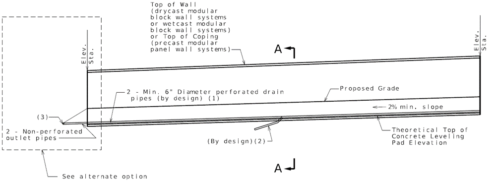 ELEVATION SHOWING DRAIN PIPE
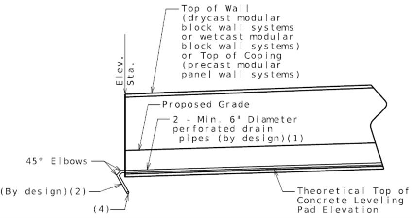 Alternate option

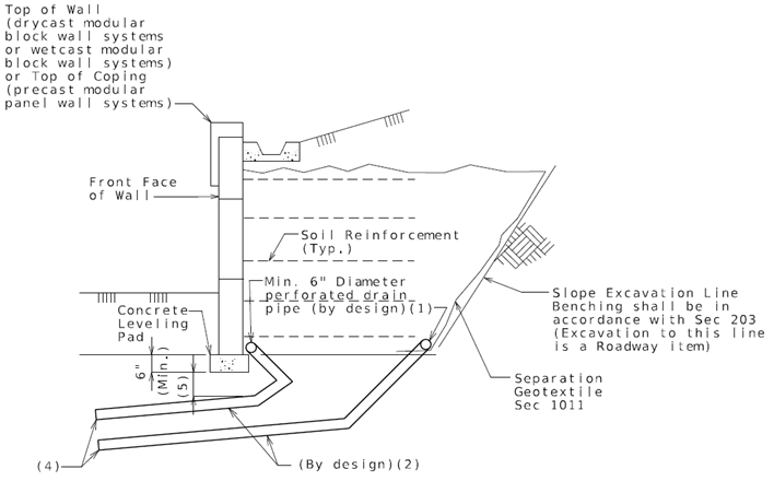 Section A-A


