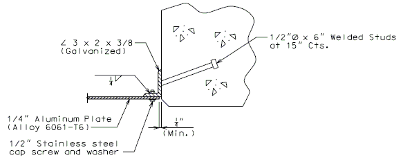
751.33 Concrete Semi Deep Abutments
Contents
751.33.1 General
751.33.1.1 Material Properties
| Concrete | ||
|---|---|---|
| Class B Concrete (Substructure) | = 3.0 ksi | |
| = 10 ksi | ||
| Class B-2 Concrete (Abutment Slab) | = 4.0 ksi | |
| = 8 ksi | ||
Modulus of elasticity,
Where:
- f'c in ksi
- wc = unit weight of nonreinforced concrete = 0.145 kcf
- K1 = correction factor for source of aggregate
- = 1.0 unless determined by physical testing
Modulus of rupture,
- LRFD 5.4.2.6
Where:
- f'c is in ksi
| Reinforcing Steel | ||
|---|---|---|
| Minimum yield strength, | = 60.0 ksi | |
| Steel modulus of elasticity, | = 29000 ksi | |
751.33.2 Design
751.33.2.1 Limit States and Factors
In general, each component shall satisfy the following equation:
Where:
| = Total factored force effect | |
| = Force effect | |
| = Load modifier | |
| = Load factor | |
| = Resistance factor | |
| = Nominal resistance | |
| = Factored resistance |
Limit States
The following limit states shall be considered for abutment design:
- STRENGTH – I
- STRENGTH – III
- STRENGTH – IV
- STRENGTH – V
- SERVICE – I
- FATIGUE
- EXTREME EVENT - II
See LRFD Table 3.4.1-1 and LRFD 3.4.2 for Loads and Load Factors applied at each given limit state.
Resistance factors
- STRENGTH limit states, see LRFD 6.5.4.2 and LRFD 5.5.4.2
- For all other limit states, = 1.00
751.33.2.2 Distribution of Loads
Dead Loads
Loads from stringers/girders shall be applied as concentrated loads at the intersection of the centerline of stringer/girder and the centerline of the bearing.
Loads from abutment components (abutment slab, barrier or railing, wings, apron, curtain wall, etc.) shall be applied to the bearing beam and transverse approach beam respectively as uniform distributed loads for the computation of pile loads and reinforcement.
Live Loads
Loads from stringers/girders shall be applied as concentrated loads at the intersection of the centerline of stringer/girder and the centerline of the bearing. Loads from the Abutment Slab shall be applied to the Transverse Approach Beam as a uniform distributed load for the computation of pile loads and reinforcement. No Live load shall be distributed through the Abutment Slab to the Bearing Beam for computations of pile loads or reinforcement
Wind, Temperature, Frictional Loads
These loads shall be disregarded, except for special cases or if specified by the Structural Project Manager, or on the Design Layout Sheet.
Earth Pressure Loads
Earth pressure loads are applied to the apron wall and part of the wing wall that extends past the transverse approach beam respectively. All tables have these forces already incorporated. For all special designs, these forces shall be applied appropriately.
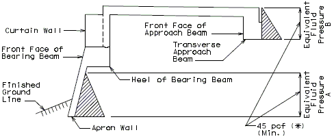
(*) Or compute using the angle, when it is given
Note: Do not use earth pressure on the front faces.
Elevation751.33.2.3 Design Assumptions
Abutment Slab
Assume a uniform 3” wearing surface load. Assume slab to be acting one-way parallel with roadway.
Bearing Beam
The beam is assumed continuous over supports at centerline of piles. Live loads are applied to the superstructure only. Live loads are not simultaneously applied to the abutment slab.
Transverse Approach Beam
The beam is assumed continuous over supports at centerline of piles. The beam is assumed to carry half of the dead load of the approach slab. Live loads are applied to the abutment slab only. Live loads are not simultaneously applied to the approach slab.
Apron Wall
Assume apron wall to be cantilevered off of bearing beam with no support from battered piles. Use an equivalent fluid pressure of 45 pcf.
Wing Wall
Assume wing wall to be cantilevered at the fill face side of the transverse approach beam.
Assume 1’-0” of soil braces wing wall bottom at short end of wall.
Use an equivalent fluid pressure of 45 pcf.
Include a collision impact load applied to the barrier or railing transferred to the wing.
Assume LL surcharge lateral load of 90 pcf.
Piles
Stresses in the piles due to bending need not be considered in design calculations, except for seismic design.
751.33.2.4 Design Process
There are many ways to go about designing a Semi-Deep Abutment. Below is one process, which will work for most standard abutments. A majority of the steps are interchangeable, and can be switched to meet the designers’ preference.
- Design geometry of abutment
- Calculate the size and number of piles required for the bearing beam
- Determine the bearing beam reinforcement
- Calculate the size and number of piles required for the transverse beam
- Determine the other abutment components reinforcement
751.33.3 Geometry
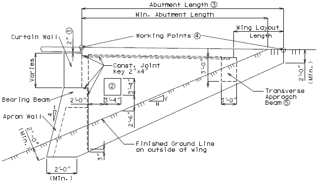
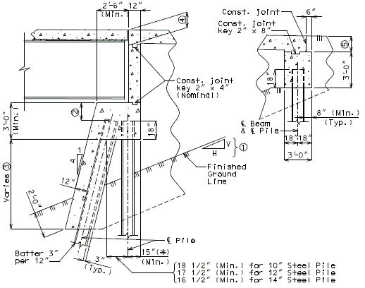
Use the standard illustrations in this section, information from your superstructure calculations, and the design layout sheet to design the geometry of the abutment.
751.33.3.1 Wing Elevation
751.33.3.2 Cross-Section
751.33.3.3 Plan View
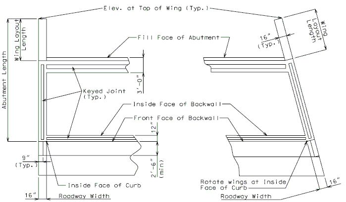
| |
| Square Structures | Skewed Structures |
|---|---|
| Plan View | |
751.33.3.4 Front Elevation
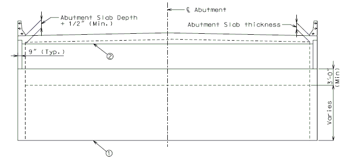
| Slope toe of Apron Wall when the ends of the walls differ in elevations by more than 2’-0”. (or when beam is sloped) | |
| Slope top of backwall when the slab haunch exceeds 6” (at gutter line). |
751.33.3.5 Pile Location
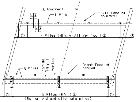
| 21” (Min.), 2’-0” (Max). | |
| 30” or 2.5 x pile diameter (Min.), 12’-0” (Max.) spacing, 1” increments. | |
| (*) | Provide a minimum of 8" cl. from outside edge of pile to face of beam. |
751.33.4 Reinforcement
751.33.4.1 Front Elevation
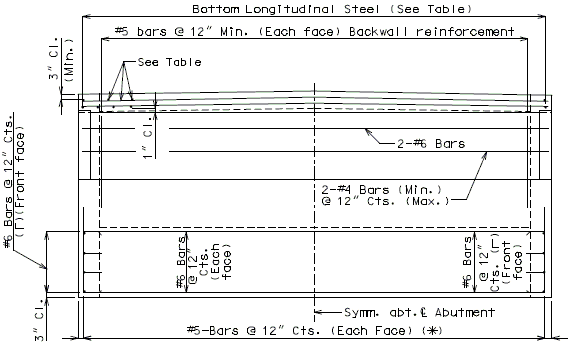
See Table below for reinforcement not shown.
All transverse steel to be placed parallel to the backwall. All main steel to be placed parallel to the centerline of roadway.
Epoxy coat all reinforcing in abutment slab, bearing beam, curtain wall, apron wall, backwall, and transverse approach beam.
When expansion devise is present use details of protective coating and sloping top of beam to drain.
(*) If height of Equivalent Fluid Pressure A is greater than 5 ft. or if apron wall extends more than 15 ft. below bearing beam, reinforcement will need to be verified.
751.33.4.2 Wing Elevation
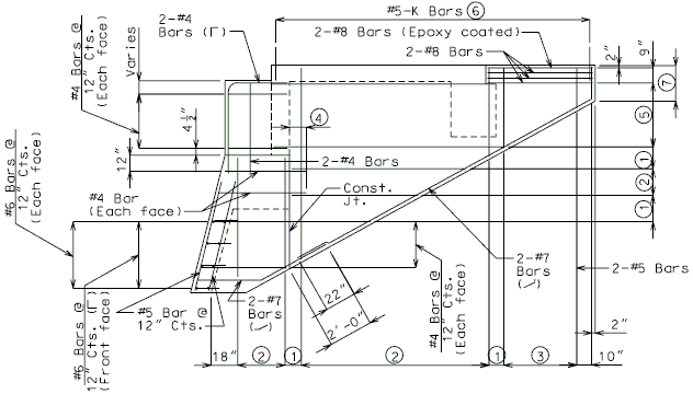
| Varies (12” Max.) | |
| #4 Bars at 12” cts. (Each face) | |
| #5 Bars at 12” cts. (Each face) | |
| 12” (Min.) (Development length) | |
| #6 Bars at 8” cts. (Each face) | |
| For details of K bars, see EPG 751.12.1.4.3 End of Barrier Reinforcement for Type B barrier and EPG 751.12.1.3.3 End of Barrier Reinforcement for Type D and H barriers. | |
| If end of wing wall is greater than 5’-0” deep, reinforcement will need to be verified. |
751.33.4.3 Cross-Section
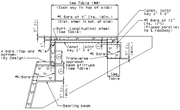
| See Table below for reinforcement. | |
| 2 1/2" Cl. (To clear the const. joint key). | |
| #4 @ 12" cts. (Max). |
| Abutment Slab Design Lengths (*) |
Uniform Abutment Slab Thickness |
Axle Vehicle Live Load (***) |
Abutment Slab Bottom Steel Parallel to C.L. Rdwy. |
Abutment Slab Top Steel Each Way |
Transverse Approach Beam Reinforcement (Top & Bot.) (****) | |||||
| Pile Spacing | ||||||||||
| 7' | 8' | 9' | 10' | 11' | 12' | |||||
| 10'-0" | 11" | 40.00 k | #8 at 9" cts. | #4 at 18" cts. | 4-#6 | 4-#6 | 4-#6 | 4-#6 | 4-#7 | 4-#8 |
| 15'-0" | 12" | 43.33 k | #8 at 8" cts. | #4 at 12" cts. | 4-#6 | 4-#6 | 4-#6 | 4-#7 | 4-#7 | 4-#8 |
| 20'-0" | 15" | 45.00 k | #8 at 7" cts. | #4 at 12" cts. | 4-#6 | 4-#6 | 4-#7 | 4-#7 | 4-#8 | 4-#8 |
| 25'-0" | 17" | 46.08 k | #8 at 5" cts. | #4 at 12" cts. | 4-#6 | 4-#6 | 4-#7 | 4-#7 | 4-#8 | 6-#8 |
| 30'-0" | 20" | 49.60 k | #9 at 6" cts. | #5 at 12" cts. | 4-#6 | 4-#7 | 4-#7 | 4-#8 | 6-#8 | 6-#8 |
| 35'-0" | 22" | 52.80 k | #9 at 5" cts. | #5 at 12" cts. | 4-#6 | 4-#7 | 4-#8 | 4-#8 | 6-#8 | 6-#8 |
| Transverse Approach Beam Stirrup Size | #4 | #4 | #5 | #5 | #6 | #6 | ||||
(*) Abutment slab design length is measured from the center of the backwall to the center of the approach beam along the centerline of roadway.
(**) For abutment slabs with lengths greater than 35’-0”, an intermediate bent is required inside the semi-deep abutment. Top and bottom reinforcement for these slabs shall be designed by the designer.
(***) Use the axle vehicle live load for calculating pile loads for the transverse approach beam.
(****) 4-#9’s can be used in lieu of 6-#8’s if spacing restrictions require fewer bars.
751.33.4.4 Plan View
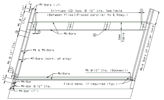
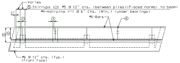
| See table above for reinforcement not shown. | |
| Use 3” (min.) and 6” (max.) (Typ.). | |
| See EPG 751.33.4.5 | |
| Varies (12” max.) | |
| Stirrup to be centered over pile (Typ.). | |
| If nominal pile capacity is greater than 110 tons, stirrup size and spacing needs to be verified. |
751.33.4.5 Bearing Beam

| = | |
| = Superstructure Loads (Applied through beam seat) | |
| = Uniform DL (Abutment Components) | |
| = Pile Spacing (ft.) |
| Min. Reinforcement: | 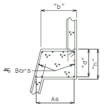
|
| Crack Control Parameters: | |
See LRFD 5.7.3.4 for variable definitions.
751.33.4.6 Pile Haunches
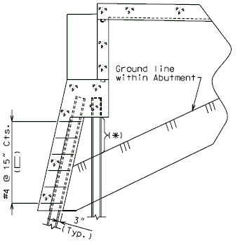
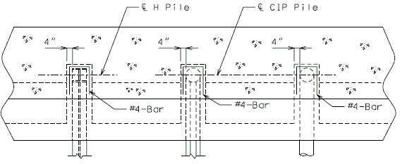
751.33.5 Details
751.33.5.1 Front Sheet
Figure shown below is an example of the information to be included on the abutment plan view on the first sheet of the plans.
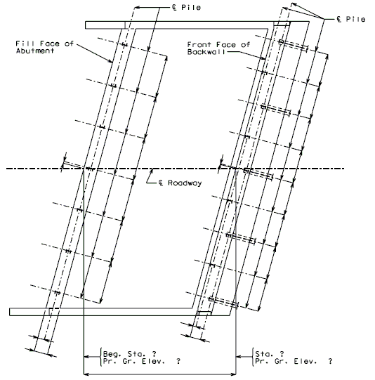
Details for unsymmetrical roadways will require dimensions tying centerline of roadway to centerline of structure. (Pile coordinates shall be to centerline of roadway)
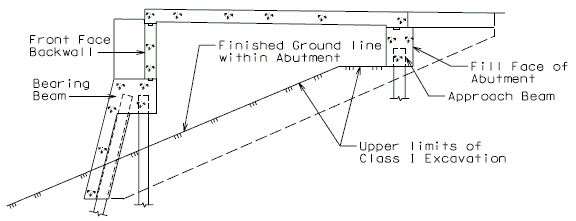
751.33.5.2 Ground line within Abutments
Figure shown below shall be detailed on the first or second sheet of the plans.
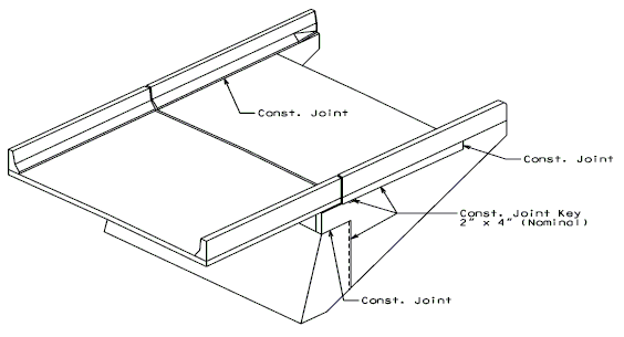
751.33.5.3 Construction Joints
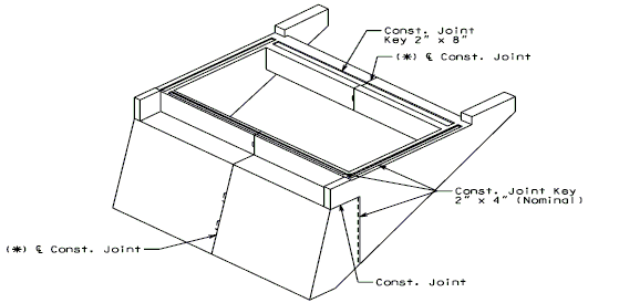
(*) When the total length of beam and backwall exceeds 60'-0", use keyed construction joint at or near centerline Abutment as shown, perferably located at a 1/4 point between piles
751.33.5.4 Access Door
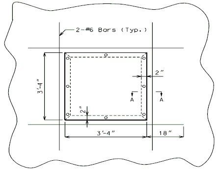
- Cost of the door is to be included in other items.
- Cut or bend reinforcing steel in the field to clear the opening for the access door.
