(6 intermediate revisions by the same user not shown)
Line 159:
Line 159:
:5) Global Stability: Confirm the global stability of the wall system as per FHWA GEC 011 and LRFD BDS 11.6.3.7 to confirm it meets the factor of safety requirements for all applicable loading conditions.
:5) Global Stability: Confirm the global stability of the wall system as per FHWA GEC 011 and LRFD BDS 11.6.3.7 to confirm it meets the factor of safety requirements for all applicable loading conditions.
:: Compare the computed factor of safety to the limit factor of safety (= 1.0):
:: Compare the computed factor of safety to the limit factor of safety (= 1.0):
::a) If the computed factor of safety is approximately equal to or exceeds 1.0, the design is considered acceptable. Resistance factors (RF) used in LRFD slope stability analysis and Factor-of-Safety (FS) results from non-LRFD slope stability analysis are presented below.
:: If the computed factor of safety is approximately equal to or exceeds 1.0, the design is considered acceptable. Resistance factors (RF) used in LRFD slope stability analysis and Factor-of-Safety (FS) results from non-LRFD slope stability analysis are presented below.
:::1) RF=0.75 (FS = 1.30) where the geotechnical parameters and subsurface stratigraphy are well-defined, and the slope or MSE wall DOES NOT support or contain a structural element (i.e., building, bridge abutment, etc. that is located within the critical failure surface) and for any temporary MSE wall.
::: a) RF=0.75 (FS = 1.30) where the geotechnical parameters and subsurface stratigraphy are well-defined, and the slope or MSE wall DOES NOT support or contain a structural element (i.e., building, bridge abutment, etc. that is located within the critical failure surface) and for any temporary MSE wall.
:::2) RF=0.65 (FS = 1.50) where the geotechnical parameters and subsurface stratigraphy are highly variable, are based on limited information, or the slope or MSE wall supports or contains a structural element such as bridge abutment fill.
::: b) RF=0.65 (FS = 1.50) where the geotechnical parameters and subsurface stratigraphy are highly variable, are based on limited information, or the slope or MSE wall supports or contains a structural element such as bridge abutment fill.
:::3) RF=0.9 (FS = 1.1) should be used for seismic analysis slopes involving or adjacent to walls and structure foundations.
::: c) RF=0.9 (FS = 1.1) should be used for seismic analysis slopes involving or adjacent to walls and structure foundations.
::b) If the factor of safety is significantly greater than 1.0, changes to reduce the computed factor of safety may be considered if significant cost savings can be realized.
::c) If the factor of safety is less than 1.0, the designer must consider alternative measures to increase the factor of safety and repeat the procedure until a factor of safety approximately equal to 1.0 is achieved.
Current procedures will factor the undrained shear strength, ''s<sub>u</sub>'', or the Mohr-Coulomb shear strength parameters, ''c'' and ''ϕ'' (or <math>\overline{c}</math> and <math> \overline{\phi}</math>). Resistance factors for factoring of these parameters are provided in EPG 321.1.2.4.
===321.1.2.3 Load Factors===
===321.1.2.3 Load Factors===
Line 330:
Line 325:
===720.2.1 MSE Wall Systems (Permanent MSE Wall Systems and Temporary MSE Wall Systems) Specified on Plan Details===
===720.2.1 MSE Wall Systems (Permanent MSE Wall Systems and Temporary MSE Wall Systems) Specified on Plan Details===
The contractor shall be responsible for the internal and external stability of the structure including compound stability. Typically, the wall manufacturer/designer will provide these requirements for the contractor. For permanent MSE walls the owner (the Geotechnical Engineer of record or their agent) is responsible for the in-situ soil design parameters on plan details, foundation bearing capacity/resistance, settlement, and overall global stability. The contractor is responsible for verifying that the applied bearing stress is less than the provided bearing capacity/resistance. For staged bridge construction, see [[751.1_Preliminary_Design#751.1.2.11_Staged_Construction|EPG 751.1.2.11 Staged Construction]].
The contractor shall be responsible for the internal and external stability of the structure including compound stability. Typically, the wall manufacturer/designer will provide these requirements for the contractor. For permanent MSE walls the owner (the Geotechnical Engineer of record or their agent) is responsible for the in-situ soil design parameters on plan details, foundation bearing capacity/resistance, settlement, and overall global stability. The contractor is responsible for verifying that the applied bearing stress is less than the provided bearing capacity/resistance. For staged bridge construction, see [[751.1_Preliminary_Design#751.1.2.11_Staged_Construction|EPG 751.1.2.11 Staged Construction]].
Global (overall) stability of a permanent MSE wall shall be performed by the Geotechnical Section or their agent and the global stability of a temporary MSE wall shall be performed by the contractor/wall designer. The compound stability of a permanent MSE wall and temporary MSE wall shall be performed by the contractor/wall designer.
Global (overall) stability of a permanent MSE wall shall be performed by the Geotechnical Section or their agent and the global stability of a temporary MSE wall shall be performed by the contractor/wall designer. The compound stability of a permanent MSE wall and temporary MSE wall shall be performed by the contractor/wall designer.
Line 338:
Line 333:
For MSE walls settlement limit, see [[321.2_Geotechnical_Guidelines#321.2.4.2_Walls|EPG 321.2.4.2 Walls]].
For MSE walls settlement limit, see [[321.2_Geotechnical_Guidelines#321.2.4.2_Walls|EPG 321.2.4.2 Walls]].
For temporary MSE walls the contractor will use the in-situ soil design parameters provided by the owner for the permanent MSE wall, but the contractor is responsible for global stability. Typically, the tallest portion of a temporary MSE wall is constructed at the same foundation elevation as the permanent wall except case 2, option 1 where the temporary wall is required to retain the improved foundation. Temporary MSE wall for staged bridge construction might have much higher height than permanent MSE wall height. It is important to ensure that global stability has been performed by the contractor for the temporary wall. For additional information, see [[751.24_LFD_Retaining_Walls#751.24.2_Mechanically_Stabilized_Earth_.28MSE.29_Walls|EPG 751.24.2 Mechanically Stabilized Earth (MSE) Walls]]. Typical examples for temporary MSE walls are given below.
For temporary MSE walls the contractor will use the in-situ soil design parameters provided by the owner for the permanent MSE wall, but the contractor is responsible for global stability. Typically, the tallest portion of a temporary MSE wall is constructed at the same foundation elevation as the permanent wall except case 2, option 1 where the temporary wall is required to retain the improved foundation. Temporary MSE wall for staged bridge construction might have much higher height than permanent MSE wall height. It is important to ensure that global stability has been performed by the contractor for the temporary wall. For additional information, see [[751.24_LFD_Retaining_Walls#751.24.2_Mechanically_Stabilized_Earth_.28MSE.29_Walls|EPG 751.24.2 Mechanically Stabilized Earth (MSE) Walls]]. Typical examples for temporary MSE walls are given below.
For temporary MSE wall, global stability shall be evaluated for the Strength Limit State. The resistance factor for global stability of the temporary MSE wall should be 0.75 (factor of safety 1.3).
For temporary MSE wall, global stability shall be evaluated for the Strength Limit State. The resistance factor for global stability of the temporary MSE wall should be 0.75 (factor of safety 1.3).
Line 482:
Line 477:
===751.1.2.2 Wing Lengths===
===751.1.2.2 Wing Lengths===
The purpose of wings is to contain and stabilize the abutment fill as the roadway transitions to the bridge. For stream crossings in particular, the wings also protect the abutment during extreme hydraulic events.
The purpose of wings is to contain and stabilize the abutment fill as the roadway transitions to the bridge. For stream crossings in particular, the wings also protect the abutment during extreme hydraulic events.
The lengths of the wings at the end bents are to be determined prior to the issuance of the Bridge Memorandum. There are two reasons for this. First, the district will use these lengths to determine the placement of their guardrail (bridge anchor section). Second, if the lengths of the wings exceed 22 ft. for seismic design category A or 17 ft. for seismic design category B, C or D, they will have to be broken into a stub wing and a detached wing wall. If this happens, then you will need to include this extra cost in your Preliminary Cost Estimate and request soundings for the wall. The request for soundings for the wall should include a request for the determination of the nominal bearing resistance and resistance factor of the soil (if in cut - assume piling if it is in fill) and the angle of internal friction for the material retained by the detached wing wall. Also include the bottom of wing footing elevation.
The lengths of the wings at the end bents are to be determined prior to the issuance of the Bridge Memorandum. There are two reasons for this. First, the district will use these lengths to determine the placement of their guardrail (bridge anchor section). Second, if the lengths of the wings exceed 22 ft. for seismic design category A or 17 ft. for seismic design category B, C or D, they will have to be broken into a stub wing and a detached wing wall. If this happens, then you will need to include this extra cost in your Preliminary Cost Estimate and request soundings for the wall. The request for soundings for the wall should include a request for the determination of the nominal bearing resistance and resistance factor of the soil (if in cut - assume piling if it is in fill) and the angle of internal friction for the material retained by the detached wing wall. Also include the bottom of wing footing elevation.
In order to use a standard end section for Type D barrier on a short turned-back wing, consider increasing the wing length so that the barrier end section is at least 8 feet long.
In order to use a standard end section for Type D barrier on a short turned-back wing, consider increasing the wing length so that the barrier end section is at least 8 feet long.
Line 490:
Line 485:
'''Unequal Wing Lengths'''
'''Unequal Wing Lengths'''
Wing lengths at each end of a bridge could be unequal because of several factors: grade of roadway under, superelevation of bridge, skew of the bridge, and/or other ramps/roads/slopes adjacent to the bridge structure, e.g., stream access roads or unusual geomorphic conditions.
Wing lengths at each end of a bridge could be unequal because of several factors: grade of roadway under, superelevation of bridge, skew of the bridge, and/or other ramps/roads/slopes adjacent to the bridge structure, e.g., stream access roads or unusual geomorphic conditions.
Set/determine the wing lengths using the control points, as shown in [[Media:611.1 Embankment at Bridge Ends.pdf|Embankment at Bridge Ends]], which may be used for both grade separations and stream crossings. This is done after the end bent location is determined. If estimated wing lengths are within 3 ft., they should be made equal and based on the longer wing length. Make sure no slope is steeper than that recommended in the geotechnical preliminary report. Slightly flatter slopes are acceptable. The contractor will warp the slopes to fit the wing tip locations.
Set/determine the wing lengths using the control points, as shown in [[Media:611.1 Embankment at Bridge Ends.pdf|Embankment at Bridge Ends]], which may be used for both grade separations and stream crossings. This is done after the end bent location is determined. If estimated wing lengths are within 3 ft., they should be made equal and based on the longer wing length. Make sure no slope is steeper than that recommended in the geotechnical preliminary report. Slightly flatter slopes are acceptable. The contractor will warp the slopes to fit the wing tip locations.
Equal wing lengths are preferable at stream crossings to mitigate scour, improve erosion control and improve/mitigate parallel water flow along wing and side embankment. Also, since wing lengths are reported to districts for use in estimating rock slope protection limits, unequal lengths (especially on the upstream side) could mistakenly lead to the unfavorable condition of allowing for less than adequate rock side slope protection.
Equal wing lengths are preferable at stream crossings to mitigate scour, improve erosion control and improve/mitigate parallel water flow along wing and side embankment. Also, since wing lengths are reported to districts for use in estimating rock slope protection limits, unequal lengths (especially on the upstream side) could mistakenly lead to the unfavorable condition of allowing for less than adequate rock side slope protection.
Line 505:
Line 500:
===751.1.2.31 Finishing Up Design Layout===
===751.1.2.31 Finishing Up Design Layout===
Design Layouts shall be generated for new bridges, retaining walls and when foundation work is required for bridge widenings. Otherwise, Design Layouts are not utilized for conveyance of information related to rehabilitation projects, or work on existing bridges or, more generally, on structures.
Design Layouts shall be generated for new bridges, retaining walls and when foundation work is required for bridge widenings. Otherwise, Design Layouts are not utilized for conveyance of information related to rehabilitation projects, or work on existing bridges or, more generally, on structures.
Once the Preliminary Detailer has created the Design Layout Sheet and added the borings and details of the proposed bridge to the plat and profile sheets, they should be checked by the Preliminary Designer. These sheets are the end product of the Preliminary Design process and will be used to perform the structural calculations for the Final Design phase of the bridge, which results in the production of the contract plans. Here is a list of items to include.
Once the Preliminary Detailer has created the Design Layout Sheet and added the borings and details of the proposed bridge to the plat and profile sheets, they should be checked by the Preliminary Designer. These sheets are the end product of the Preliminary Design process and will be used to perform the structural calculations for the Final Design phase of the bridge, which results in the production of the contract plans. Here is a list of items to include.
| || c. || Minimum tip elevations for all piles.
| || c. || Minimum tip elevations for all piles.
Line 574:
Line 568:
| || d. || Location and elevation for any preboring.
| || d. || Location and elevation for any preboring.
|- style="vertical-align:top;"
|- style="vertical-align:top;"
| ||e. || Pile point reinforcement (shoes) required for all structural steel HP piles. When Geotechnical Section indicates pile point reinforcement needed and show pile point type on boring log for CIP pile, then recommended pile point reinforcement type shall be shown on Design Layout.
| || e. || Pile point reinforcement (shoes) required for all structural steel HP piles. When Geotechnical Section indicates pile point reinforcement needed and show pile point type on boring log for CIP pile, then recommended pile point reinforcement type shall be shown on Design Layout.
|-
|-
| || f. || For end bearing pile when Geotechnical Section recommends dynamic pile testing (PDA) for pile driving verification method then reflect that on Design Layout.
| || f. || For end bearing pile when Geotechnical Section recommends dynamic pile testing (PDA) for pile driving verification method then reflect that on Design Layout.
|-
|-
| || g. || Types of footings, their elevations and allowable bearing (if applicable).
| || g. || Types of footings, their elevations, nominal bearing resistance and resistance factor (if applicable).
|-
|-
| || h. || Location of any cofferdams and/or seal courses.
| || h. || Location of any cofferdams and/or seal courses.
Line 670:
Line 664:
|}
|}
Once the Preliminary Detailer and Designer are in agreement on these items, the entire layout folder should be submitted to the SPM for their review. The SPM will then request a Design Layout Conference with the Assistant State Bridge Engineer and the Structural Resource Manager.
Once the Preliminary Detailer and Designer are in agreement on these items, the entire layout folder should be submitted to the SPM for their review. The SPM will then request a Design Layout Conference with the Assistant State Bridge Engineer and the Structural Resource Manager.
Following this conference, the Preliminary Detailer and Designer will make any requested changes and complete the assembly of the Layout Folder by including the approved Design Layout Sheet and one set of half sized plat and profile sheets. The Layout Folder should then be delivered to the SPM along with one set of half-sized plat and profile sheets and a copy of the Design Layout Sheet.
Following this conference, the Preliminary Detailer and Designer will make any requested changes and complete the assembly of the Layout Folder by including the approved Design Layout Sheet and one set of half sized plat and profile sheets. The Layout Folder should then be delivered to the SPM along with one set of half-sized plat and profile sheets and a copy of the Design Layout Sheet.
The SPM should then use a cover letter to send the one set of half-sized plat and profile sheets, as well as the copy of the Design Layout Sheet, to the Transportation Project Manager in the district. Include in this cover letter any changes in the Preliminary Cost Estimate and the current Plans Completion Date. An example can be found on the next page.
The SPM should then use a cover letter to send the one set of half-sized plat and profile sheets, as well as the copy of the Design Layout Sheet, to the Transportation Project Manager in the district. Include in this cover letter any changes in the Preliminary Cost Estimate and the current Plans Completion Date. An example can be found on the next page.
The Preliminary Detailer should provide a copy of the Design Layout Sheet to the Bridge Survey Processor. The Bridge Survey Processor should then perform the following tasks:
The Preliminary Detailer should provide a copy of the Design Layout Sheet to the Bridge Survey Processor. The Bridge Survey Processor should then perform the following tasks:
*Enter the Date to Final Design in the Bridge Survey Book and the Survey Rcv. Database
*Enter the Date to Final Design in the Bridge Survey Book and the Survey Rcv. Database
*Supply a copy of the Design Layout Sheet to Development and Review.
*Supply a copy of the Design Layout Sheet to Development and Review.
Once you determine that you must use a CIP wall, there is very little to do as far as the layout of the structure. Both the horizontal alignment and the top of wall elevations are supplied by the district in the Bridge Survey. You do need to check the top of wall elevations to make sure the district accounted for any concrete gutters placed behind the top of the wall. These are necessary if the slope of the fill will direct water towards the top of the wall. The district should decide whether to use Type A or Type B gutters ([http://www.modot.mo.gov/business/standards_and_specs/documents/60900.pdf Standard Plan 609.00]), or Modified Type A or Modified Type B gutters ([http://www.modot.mo.gov/business/standards_and_specs/documents/60711.pdf Standard Plan 607.11]) if fencing is required, and where they should drain to.
You will also need to set the elevations for the top of the footing, which should be a minimum of 2 feet below the finished ground line for walls south of Interstate 70 and 3 feet below the finished ground line for walls north of Interstate 70. In tight roadway situations where a barrier or railing is to be placed on top of the wall, make sure that a stem thickness of 16 inches will fit.
Check with the district contact to determine if they want any coping on the exposed face of the wall.
French drains will be used to relieve water pressure behind the CIP wall as a default. If you expect to encounter springs or swampy conditions, then check with the district contact on calling for an underdrain. If the decision is made to use an underdrain, the porous backfill and pipes are Roadway Items and this must be noted on the Bridge Memorandum and Design Layout.
For details on requesting soundings, see [[751.1_Preliminary_Design#751.1.2.19_Soundings_.28Borings.29|EPG 751.1.2.19 Soundings (Borings)]].
If the preliminary geotechnical report or historical boring data at the location indicates the presence of soft clays or loose sands or the foundation material is very poor in quality, consider piling and include in the Preliminary Cost Estimate. Preliminary cost estimating should follow [[751.1_Preliminary_Design#751.1.2.17_Preliminary_Cost_Estimate|EPG 751.1.2.17 Preliminary Cost Estimate]] and be based upon unit price bid history. More refined cost estimating should follow cost-basing estimating.
Designs of Mechanically Stabilized Earth (MSE) walls shall be completed by consultants or contractors in accordance with Section 11.10 of LRFD specifications, FHWA-NHI-10-024 and FHWA-NHI-10-025 for LRFD. [https://www.modot.org/bridge-pre-qualified-products-list Bridge Pre-qualified Products List (BPPL)] provided on MoDOT's web page and in Sharepoint contains a listing of facing unit manufacturers, soil reinforcement suppliers, and wall system suppliers which have been approved for use. See [http://www.modot.org/business/standards_and_specs/SpecbookEPG.pdf#page=11 Sec 720] and [http://www.modot.org/business/standards_and_specs/SpecbookEPG.pdf#page=14 Sec 1010] for additional information. The Geotechnical Section is responsible for checking global stability of permanent MSE wall systems, which should be reported in the Foundation Investigation Geotechnical Report. For MSE wall preliminary information, see [[751.1_Preliminary_Design#751.1.4.3_MSE_Walls|EPG 751.1.4.3 MSE Walls]]. For design requirements of MSE wall systems and temporary shoring (including temporary MSE walls), see [[:Category:720_Mechanically_Stabilized_Earth_Wall_Systems#720.2_Design_Requirements|EPG 720 Mechanically Stabilized Earth Wall Systems]]. For staged bridge construction, see [[751.1_Preliminary_Design#751.1.2.11_Staged_Construction|EPG 751.1.2.11 Staged Construction]].
Global (overall) stability of a permanent MSE wall shall be performed by the Geotechnical Section or their agent and the global stability of a temporary MSE wall shall be performed by the contractor/wall designer. The cCompound stability of a permanent MSE wall and temporary MSE wall shall be performed by the contractor/wall designer.
Global stability (i.e., overall and compound stability) of the wall shall be performed in accordance with FHWA GEC 011, and LRFD BDS 11.6.3.7 and 11.10.5.6. For additional information, See [[321.1_Design_of_Earth_Slopes#321.1.2_Slope_Stability_Analyses_for_Special_Foundation_Investigations|EPG 321.1.2 Slope Stability Analyses for Special Foundation Investigations]].
For seismic design requirements, see [https://epg.modot.org/forms/general_files/BR/Bridge_Seismic_Design_Flowchart.pdf Bridge Seismic Design Flowchart]. References for consultants and contractors include Section 11.10 of LRFD, FHWA-NHI-10-024 and FHWA-NHI-10-025.
'''Design Life'''
* 75 year minimum for permanent walls (if retained foundation require 100 year than consider 100 year minimum design life for wall).
'''Global stability:'''
Global stability will be performed by Geotechnical Section or their agent.
:: Factored bearing resistance = Nominal bearing resistance from the Geotechnical report * Resistance factor.
:: For walls that DO NOT contain or support a structure use resistance factor per LRFDLRFD BDS Table 11.5.7-1.
:: For walls that contain or support a structure use resistance factor per LRFD BDS Table 10.5.5.2.2-1 or as otherwise recommended in the Geotechnical report.
:: Resistance factor = 0.9 in accordance with LRFD BDS 11.5.8
:: Factored bearing stress shall be computed using a uniform base pressure distribution over an effective width of footing determined in accordance with the provisions of LRFD 10.6.3.1 and 10.6.3.2, 11.10.5.4 and Figure 11.6.3.2-1 for foundation supported on soil or rock.
:: B’ = L – 2e
:: Where,
::: L = Soil reinforcement length (For modular block use B in lieu of L as per LRFD 11.10.2-1)
::: B’ = effective width of footing
::: e = eccentricity
::: Note: When the value of eccentricity e is negative then B´ = L.
::Capacity/Demand ratio (CDR) for overturning shall be ≥ 1.0
::: For foundations supported on soil or rock, the location of the resultant of the reaction forces shall be within the middle two-thirds of the base width, L or (e ≤ 0.33L).
::Eccentricity, (e) Limit for Extreme Event I (Seismic): LRFD 11.6.5.1
:::For foundations supported on soil or rock, the location of the resultant of the reaction forces shall be within the middle two-thirds of the base width, L or (e ≤ 0.33L) for γ<sub>EQ</sub> = 0.0 and middle eight-tenths of the base width, L or (e ≤ 0.40L) for γ<sub>EQ</sub> = 1.0. For γ<sub>EQ</sub> between 0.0 and 1.0, interpolate e value linearly between 0.33L and 0.40L. For γ<sub>EQ</sub> refer to LRFD 3.4.
:::Note: Seismic design shall be performed for γ<sub>EQ</sub> = 0.5
::Eccentricity, (e) Limit for Extreme Event II:
:::For foundations supported on soil or rock, the location of the resultant of the reaction forces shall be within the middle eight-tenths of the base width, L or (e ≤ 0.40L).
'''General Guidelines'''
* Drycast modular block wall (DMBW-MSE) systems are limited to a 10 ft. height in one lift.
* Wetcast modular block wall (WMBW-MSE) systems are limited to a 15 ft. height in one lift.
* For Drycast modular block wall (DMBW-MSE) systems and Wetcast modular block wall (WMBW-MSE) systems, top cap units shall be used and shall be permanently attached by means of a resin anchor system.
* For precast modular panel wall (PMPW-MSE) systems, capstone may be substituted for coping and either shall be permanently attached to wall by panel dowels.
* For precast modular panel wall (PMPW-MSE) systems, form liners are required to produce all panels. Using form liner to produce panel facing is more cost effective than producing flat panels. Standard form liners are specified on the [https://www.modot.org/mse-wall-msew MSE Wall Standard Drawings]. Be specific regarding names, types and colors of staining, and names and types of form liner.
* MSE walls shall not be used where exposure to acid water may occur such as in areas of coal mining.
* MSE walls shall not be used where scour is a problem.
* MSE walls with metallic soil reinforcement shall not be used where stray electrical ground currents may occur as would be present near electrical substations.
* No utilities shall be allowed in the reinforced earth if future access to the utilities would require that the reinforcement layers be cut, or if there is a potential for material, which can cause degradation of the soil reinforcement, to leak out of the utilities into the wall backfill, with the exception of storm water drainage.
* All vertical objects shall have at least 4’-6” clear space between back of the wall facing and object for select granular backfill compaction and soil reinforcement skew limit requirements. For piles, see pipe pile spacers guidance.
* The interior angle between two MSE walls should be greater than 70°. However, if unavoidable, then place [[751.50_Standard_Detailing_Notes#J._MSE_Wall_Notes_.28Notes_for_Bridge_Standard_Drawings.29|EPG 751.50 J1.41 note]] on the design plans.
* Drycast modular block wall (DMBW-MSE) systems and Wetcast modular block wall (WMBW-MSE) systems may be battered up to 1.5 in. per foot. Modular blocks are also known as “segmental blocks”.
* The friction angle used for the computation of horizontal forces within the reinforced soil shall be greater than or equal to 34°.
* For epoxy coated reinforcement requirements, see [[751.5 Structural Detailing Guidelines#751.5.9.2.2 Epoxy Coated Reinforcement Requirements|EPG 751.5.9.2.2 Epoxy Coated Reinforcement Requirements]].
* All concrete except facing panels or units shall be CLASS B or B-1.
* The friction angle of the soil to be retained by the reinforced earth shall be listed on the plans as well as the friction angle for the foundation material the wall is to rest on.
* The following requirement shall be considered (from 2009_FHWA-NHI-10-024 MSE wall 132042.pdf, page 200-201) when seismic design is required:
:* For seismic design category, SDC C or D (Zones 3 or 4), facing connections in modular block faced walls (MBW) shall use shear resisting devices (shear keys, pin, etc.) between the MBW units and soil reinforcement, and shall not be fully dependent on frictional resistance between the soil reinforcement and facing blocks. For connections partially dependent on friction between the facing blocks and the soil reinforcement, the nominal long-term connection strength T<sub>ac</sub>, should be reduced to 80 percent of its static value.
* Seismic design category and acceleration coefficients shall be listed on the plans for categories B, C and D. If a seismic analysis is required that shall also be noted on the plans. See [[751.50_Standard_Detailing_Notes#A._General_Notes|EPG 751.50 A1.1 note]].
* Plans note ([[751.50_Standard_Detailing_Notes#J._MSE_Wall_Notes_.28Notes_for_Bridge_Standard_Drawings.29|EPG 751.50 J1.1]]) is required to clearly identify the responsibilities of the wall designer.
* Do not use Drycast modular block wall (DMBW-MSE) systems in the following locations:
::* Within the splash zone from snow removal operations (assumed to be 15 feet from the edge of the shoulder).
::* Where the blocks will be continuously wetted, such as around sources of water.
::* Where blocks will be located behind barrier or other obstacles that will trap salt-laden snow from removal operations.
* Do not use Drycast modular block wall (DMBW-MSE) systems or Wetcast modular block wall (WMBW-MSE) systems in the following locations:
::* For structurally critical applications, such as containing necessary fill around structures.
::* In tiered wall systems.
* For locations where Drycast modular block wall (DMBW-MSE) systems and Wetcast modular block wall (WMBW-MSE) systems are not desirable, consider coloring agents and/or architectural forms using precast modular panel wall (PMPW-MSE) systems for aesthetic installations.
* For slab drain location near MSE Wall, see [[751.10 General Superstructure#General Requirements for Location and Spacing of Slab Drains|EPG 751.10.3.1 Drain Type, Alignment and Spacing]] and [[751.10 General Superstructure#751.10.3.3 General Requirements for Location of Slab Drains|EPG 751.10.3.3 General Requirements for Location of Slab Drains]].
* Roadway runoff should be directed away from running along face of MSE walls used as wing walls on bridge structures.
* Drainage:
:*Gutter type should be selected at the core team meeting.
:* When gutter is required without fencing, use Type A or Type B gutter (for detail, see [https://www.modot.org/media/16880 Std. Plan 609.00]).
:* When gutter is required with fencing, use Modified Type A or Modified Type B gutter (for detail, see [https://www.modot.org/media/16871 Std. Plan 607.11]).
:* When fencing is required without gutter, place in tube and grout behind the MSE wall (for detail, see [https://www.modot.org/bridge-standard-drawings MSE Wall Standard Drawings - MSEW], Fence Post Connection Behind MSE Wall (without gutter).
:* Lower backfill longitudinal drainage pipes behind all MSE walls shall be two-6” (Min.) diameter perforated PVC or PE pipe (See Sec 1013) unless larger sizes are required by design which shall be the responsibility of the District Design Division. Show drainage pipe size on plans. Outlet screens and cleanouts should be detailed for any drain pipe (shown on MoDOT MSE wall plans or roadway plans). Lateral non-perforated drain pipes (below leveling pad) are permitted by Standard Specifications and shall be sized by the District Design Division if necessary. Lateral outlet drain pipe sloped at 2% minimum.
::* Identify on MSE wall plans or roadway plans drainage pipe point of entry, point of outlet (daylighting), 2% min. drainage slopes in between points to ensure positive flow and additional longitudinal drainage pipes if required to accommodate ground slope changes and lateral drainage pipes if required by design.
::* Adjustment in the vertical alignment of the longitudinal drainage pipes from that depicted on the MSE wall standard drawings may be necessary to ensure positive flow out of the drainage system.
::* Identify on MSE wall plans or roadway plans the outlet ends of pipes which shall be located to prevent clogging or backflow into the drainage system. Outlet screens and cleanouts should be detailed for any drain pipe.
:* For more information on drainage, see [[#Drainage at MSE Walls|Drainage at MSE Walls]].
For bridges not longer than 200 feet, pipe pile spacers or pile jackets shall be used at pile locations behind mechanically stabilized earth walls at end bents. Corrugated pipe pile spacers are required when the wall is built prior to driving the piles to protect the wall reinforcement when driving pile for the bridge substructure at end bents(s). Pile spacers or pile jackets may be used when the piles are driven before the wall is built. Pipe pile spacers shall have an inside diameter greater than that of the pile and large enough to avoid damage to the pipe when driving the pile. Use [[751.50 Standard Detailing Notes#E1. Excavation and Fill|EPG 751.50 Standard Detailing Note E1.2a]] on bridge plans.
For bridges longer than 200 feet, pipe pile spacers are required and the pile spacer shall be oversized to mitigate the effects of bridge thermal movements on the MSE wall. For HP12, HP14, CIP 14” and CIP 16” piles provide 24-inch inside diameter of pile spacer for bridge movement. Minimum pile spacing shall be 5 feet to allow room for compaction of the soil layers. Use [[751.50 Standard Detailing Notes#E1. Excavation and Fill|EPG 751.50 Standard Detailing Note E1.2b]] on bridge plans.
The bottom of the pipe pile spacers shall be placed 5 ft. min. below the bottom of the MSE wall leveling pad. The pipe shall be filled with sand or other approved material after the pile is placed and before driving. Pipe pile spacers shall be accurately located and capped for future pile construction.
Alternatively, for bridges shorter than or equal to 200 feet, the contractor shall be given the option of driving the piles before construction of the mechanically stabilized earth wall and placing the soil reinforcement and backfill material around the piling. In lieu of pipe pile spacers contractor may place pile jackets on the portion of the piles that will be in the MSE soil reinforced zone prior to placing the select granular backfill material and soil reinforcement. The contractor shall adequately support the piling to ensure that proper pile alignment is maintained during the wall construction. The contractor’s plan for bracing the pile shall be submitted to the engineer for review.
Piling shall be designed for downdrag (DD) loads due to either method. Oversized pipe pile spacers with sand placed after driving or pile jacket may be considered to mitigate some of the effects of downdrag (DD) loads. Sizing of pipe pile spacers shall account for pile size, thermal movements of the bridge, pile placement plan, and vertical and horizontal placement tolerances.
When rock is anticipated within the 5 feet zone below the MSE wall leveling pad, prebore into rock and prebore holes shall be sufficiently wide to allow for a minimum 10 feet embedment of pile and pipe pile spacer. When top of rock is anticipated within the 5 to 10 feet zone below the MSE wall leveling pad, prebore into rock to achieve a minimum embedment (pile only) of 10 feet below the bottom of leveling pad. Otherwise, the pipe pile spacer requires a minimum 5 feet embedment below the levelling pad. Consideration shall also be given to oversizing the prebore holes in rock to allow for temperature movements at integral end bents.
For bridges not longer than 200 feet, the minimum clearance from the back face of MSE walls to the front face of the end bent beam, also referred to as setback, shall be 4 ft. 6 in. (typ.) unless larger than 18-inch pipe pile spacer required. The 4 ft. 6 in. dimension serves a dual purpose:
:1) the setback ensures that soil reinforcement is not skewed more than 15° for nut and bolt reinforcement connections to clear an 18-inch inside diameter pipe pile spacers by 6 inches per FHWA-NHI-10-24, Figure 5-17C, while considering vertical and horizontal pile placement tolerances
:2) the setback helps to reduce the forces imparted on the MSE wall from bridge movements that typically are not accounted for in the wall design and cannot be completely isolated using a pipe pile spacer. Increasing the minimum setback shall be considered when larger diameter pile spacers are required or when other types of soil reinforcement connections are anticipated
For bridges longer than 200 feet, the minimum setback shall be 5 ft. 6 in. based on the use of 24-inch inside diameter of pipe pile spacers.
If interference with soil reinforcement is not a concern and the wall is designed for forces from bridge movement, the following guidance for pipe pile spacers clearance shall be used: pipe pile spacers shall be placed 36 in. clear min. from the back face of MSE wall panels to allow for proper compaction; 12 in. minimum clearance is required between pipe pile spacers and leveling pad and 18 in. minimum clearance is required between leveling pad and pile. For isolated pile (e.g, walls skewed from the bent orientation), the pipe pile spacer may be placed 18 in. clear min. from the back face of MSE wall panels.
'''MSE Wall Plan and Geometrics'''
* A plan view shall be drawn showing a baseline or centerline, roadway stations and wall offsets. The plan shall contain enough information to properly locate the wall. The ultimate right of way shall also be shown, unless it is of a significant distance from the wall and will have no effect on the wall design or construction.
* Stations and offsets shall be established between one construction baseline or roadway centerline and a wall control line (baseline). Some wall designs may contain a slight batter, while others are vertical. A wall control line shall be set at the front face of the wall, either along the top or at the base of the wall, whichever is critical to the proposed improvements. For battered walls, in order to allow for batter adjustments of the stepped level pad or variation of the top of the wall, the wall control line (baseline) is to be shown at a fixed elevation. For battered walls, the offset location and elevation of control line shall be indicated. All horizontal breaks in the wall shall be given station-offset points, and walls with curvature shall indicate the station-offsets to the PC and PT of the wall, and the radius, on the plans.
* Any obstacles which could possibly interfere with the soil reinforcement shall be shown. Drainage structures, lighting, or truss pedestals and footings, etc. are to be shown, with station offset to centerline of the obstacle, with obstacle size. Skew angles are shown to indicate the angle between a wall and a pipe or box which runs through the wall.
* Elevations at the top and bottom of the wall shall be shown at 25 ft. intervals and at any break points in the wall.
* Curve data and/or offsets shall be shown at all changes in horizontal alignment. If battered wall systems are used on curved structures, show offsets at 10 ft. (max.) intervals from the baseline.
* Details of any architectural finishes (formliners, concrete coloring, etc.).
* Details of threaded rod connecting the top cap block.
* Estimated quantities, total sq. ft. of mechanically stabilized earth systems.
* Proposed grade and theoretical top of leveling pad elevation shall be shown in constant slope. Slope line shall be adjusted per project. Top of wall or coping elevation and stationing shall be shown in the developed elevation per project. If leveling pad is anticipated to encounter rock, then contact the Geotechnical Section for leveling pad minimum embedment requirements.
'''MSE Wall Cross Sections'''
* A typical wall section for general information is shown.
* Additional sections are drawn for any special criteria. The front face of the wall is drawn vertical, regardless of the wall type.
* Any fencing and barrier or railing are shown.
* Barrier if needed are shown on the cross section. Barriers are attached to the roadway or shoulder pavement, not to the MSE wall. Standard barriers are placed along wall faces when traffic has access to the front face of the wall over shoulders of paved areas.
<div id="Drainage at MSE Walls"></div>
'''Drainage at MSE Walls'''
*'''Drainage Before MSE Wall'''
:Drainage is not allowed to be discharged within 10 ft. from front of MSE wall in order to protect wall embedment, prevent erosion and foundation undermining, and maintain soil strength and stability.
*'''Drainage Behind MSE Wall'''
::'''Internal (Subsurface) Drainage'''
::Groundwater and infiltrating surface waters are drained from behind the MSE wall through joints between the face panels or blocks (i.e. wall joints) and two-6 in. (min.) diameter pipes located at the base of the wall and at the basal interface between the reinforced backfill and the retained backfill.
::Excessive subsurface draining can lead to increased risk of backfill erosion/washout through the wall joints and erosion at the bottom of walls and at wall terminal ends. Excessive water build-up caused by inadequate drainage at the bottom of the wall can lead to decreased soil strength and wall instability. Bridge underdrainage (vertical drains at end bents and at approach slabs) can exacerbate the problem.
::Subsurface drainage pipes should be designed and sized appropriately to carry anticipated groundwater, incidental surface run-off that is not collected otherwise including possible effects of drainage created by an unexpected rupture of any roadway drainage conveyance or storage as an example.
::'''External (Surface) Drainage'''
::External drainage considerations deal with collecting water that could flow externally over and/or around the wall surface taxing the internal drainage and/or creating external erosion issues. It can also infiltrate the reinforced and retained backfill areas behind the MSE wall.
::Diverting water flow away from the reinforced soil structure is important. Roadway drainage should be collected in accordance with roadway drainage guidelines and bridge deck drainage should be collected similarly.
*'''Guidance'''
:ALL MSE WALLS
:1. Appropriate measures to prevent surface water infiltration into MSE wall backfill should be included in the design and detail layout for all MSE walls and shown on the roadway plans.
:2. Gutters behind MSE walls are required for flat or positive sloping backfills to prevent concentrated infiltration behind the wall facing regardless of when top of backfill is paved or unpaved. This avoids pocket erosion behind facing and protection of nearest-surface wall connections which are vulnerable to corrosion and deterioration. Drainage swales lined with concrete, paved or precast gutter can be used to collect and discharge surface water to an eventual point away from the wall. If rock is used, use impermeable geotextile under rock and align top of gutter to bottom of rock to drain. (For negative sloping backfills away from top of wall, use of gutters is not required.)
:District Design Division shall verify the size of the two-6 in. (min.) diameter lower perforated MSE wall drain pipes and where piping will daylight at ends of MSE wall or increase the diameters accordingly. This should be part of the preliminary design of the MSE wall. (This shall include when lateral pipes are required and where lateral drain pipes will daylight/discharge).
:BRIDGE ABUTMENTS WITH MSE WALLS
:Areas of concern: bridge deck drainage, approach slab drainage, approach roadway drainage, bridge underdrainage: vertical drains at end bents and approach slab underdrainage, showing drainage details on the roadway and MSE wall plans
:3. Bridge slab drain design shall be in accordance with [[751.10 General Superstructure#751.10.3 Bridge Deck Drainage - Slab Drains |EPG 751.10.3 Bridge Deck Drainage – Slab Drains]] unless as modified below.
:4. Coordination is required between the Bridge Division and District Design Division on drainage design and details to be shown on the MSE wall and roadway plans.
:5. Bridge deck, approach slab and roadway drainage shall not be allowed to be discharged to MSE wall backfill area or within 10 feet from front of MSE wall.
::*(Recommended) Use of a major bridge approach slab and approach pavement is ideal because bridge deck, approach slab and roadway drainage are directed using curbs and collected in drain basins for discharge that protect MSE wall backfill. For bridges not on a major roadway, consideration should be given to requiring a concrete bridge approach slab and pavement incorporating these same design elements (asphalt is permeable).
::*(Less Recommended) Use of conduit and gutters:
:::* Conduit: Drain away from bridge and bury conduit daylighting to natural ground or roadway drainage ditch at an eventual point beyond the limits of the wall. Use expansion fittings to allow for bridge movement and consider placing conduit to front of MSE wall and discharging more than 10 feet from front of wall or using lower drain pipes to intercept slab drainage conduit running through backfill.
:::* Conduit and Gutters: Drain away from bridge using conduit and 90° elbow (or 45° bend) for smoothly directing drainage flow into gutters and that may be attached to inside of gutters to continue along downward sloping gutters along back of MSE wall to discharge to sewer or to natural drainage system, or to eventual point beyond the limits of the wall. Allow for independent bridge and wall movements by using expansion fittings where needed. See [[751.10 General Superstructure#751.10.3.1 Type, Alignment and Spacing|EPG 751.10.3.1 Type, Alignment and Spacing]] and [[751.10 General Superstructure#751.10.3.3 General Requirements for Location of Slab Drains|EPG 751.10.3.3 General Requirements for Location of Slab Drains]].
:6. Vertical drains at end bents and approach slab underdrainage should be intercepted to drain away from bridge end and MSE wall.
:7. Discharging deck drainage using many slab drains would seem to reduce the volume of bridge end drainage over MSE walls.
:8. Drain flumes at bridge abutments with MSE walls do not reduce infiltration at MSE wall backfill areas and are not recommended.
:DISTRICT DESIGN DIVISION MSE WALLS
:Areas of concern: roadway or pavement drainage, MSE wall drainage, showing drainage details on the roadway and MSE wall plans.
:9. For long MSE walls, where lower perforated drain pipe slope become excessive, non-perforated lateral drain pipes, permitted by Standard Specifications, shall be designed to intercept them and go underneath the concrete leveling pad with a 2% minimum slope. Lateral drain pipes shall daylight/discharge at least 10 ft. from front of MSE wall. Screens should be installed and maintained on drain pipe outlets.
:10. Roadway and pavement drainage shall not be allowed to be discharged to MSE wall backfill area or within 10 feet from front of MSE wall.
:11. For district design MSE walls, use roadway or pavement drainage collection pipes to transport and discharge to an eventual point outside the limits of the wall.
: Example: Showing drain pipe details on the MSE wall plans.
(1) To be designed by District Design Division.</br>
(2) To be designed by District Design Division if needed. Provide non-perforated lateral drain pipe under leveling pad at 2% minimum slope. (Show on plans).</br>
(3) Discharge to drainage system or daylight screened outlet at least 10 feet away from end of wall (typ.). (Skew in the direction of flow as appropriate).</br>
(4) Discharge to drainage system or daylight screened outlet at least 10 feet away from front face of wall (typ.). (Skew in the direction of flow as appropriate).</br>
(5) Minimum backfill cover = Max(15”, 1.5 x diameter of drain pipe).</br>
Note: For design concepts and guidance, follow the design process ([[751.40_LFD_Widening_and_Repair#751.40.8.15_Cast-In-Place_Concrete_Retaining_Walls|EPG 751.40.8.15]]) and modify design/details of ASD as necessary to meet LRFD requirements until [https://epgtest.modot.org/index.php/751.24_Retaining_Walls EPG 751.24] is updated for LRFD.
Capacity/Demand ratio (CDR) for bearing capacity shall be ≥ 1.0
: Factored bearing resistance = Nominal bearing resistance from the Geotechnical report * Resistance factor .
: For walls that DO NOT contain or support a structure use resistance factor per LRFD BDS Table 11.5.7-1.
: For walls that contain or support a structure use resistance factor per LRFD BDS Table 10.5.5.2.2-1 or as otherwise recommended in the Geotechnical report.
: Extreme Event I and II Limit State:
: Factored bearing resistance = Nominal bearing resistance from Geotech report X Resistance factor
: Sliding shall be checked in accordance with LRFD 11.6.3.6 and 10.6.3.4
Eccentricity, (e) Limit for Strength Limit State: LRFD 11.6.3.3
:* For foundations supported on soil, the location of the resultant of the reaction forces shall be within the middle two-thirds of the base width, B or (e ≤ 0.33B).
:* For foundations supported on rock, the location of the resultant of the reaction forces shall be within the middle nine-tenths of the base width, B or (e ≤ 0.45B).
Eccentricity, (e) Limit for Extreme Event I (Seismic): LRFD 11.6.5.1
:* For foundations supported on soil or rock, the location of the resultant of the reaction forces shall be within the middle two-thirds of the base width, B or (e ≤ 0.33B) for γ<sub>EQ</sub> = 0.0 and middle eight-tenths of the base width, B or (e ≤ 0.40B) for γ<sub>EQ</sub> = 1.0. For γ<sub>EQ</sub> between 0.0 and 1.0, interpolate e value linearly between 0.33B and 0.40B. For γ<sub>EQ</sub> refer to LRFD 3.4.
:Note: Seismic design shall be performed for γ<sub>EQ</sub> = 0.5. If live loads act to reduce the eccentricity, then γ<sub>EQ</sub> shall be taken as 0.0.
Eccentricity, (e) Limit for Extreme Event II:
:* For foundations supported on soil or/and rock, the location of the resultant of the reaction forces shall be within the middle eight-tenths of the base width, B or (e ≤ 0.40B).
For epoxy coated reinforcement requirements, see [[751.5 Structural Detailing Guidelines#751.5.9.2.2 Epoxy Coated Reinforcement Requirements|EPG 751.5.9.2.2 Epoxy Coated Reinforcement Requirements]].
If the height of the wall or fill is a variable dimension, then base the structural design of the wall, toe, and heel on the high quarter point between expansion joints.
These boxes will provide supplemental information or commentary on application of specific provisions, supporting documentation for the provisions, or explanations for how the provisions should be applied.
This article provides requirements for design of earth slopes commonly encountered in transportation rights of way. Such slopes commonly include embankment slopes for fills and bridge approaches and excavated slopes in cut sections of roadway. Earth slopes should be designed to maintain stability for conditions and loads that can reasonably be expected to be encountered throughout the life of the slope based on available information regarding site conditions and anticipated loadings. Earth slopes should also be designed so that excessive deformations are not experienced throughout the life of the structure or so that deformations that do occur do not adversely affect the travel way.
In the context of these guidelines, “design” of earth slopes generally involves selection of some combination of the following to produce a final slope that will satisfy performance requirements:
1) Slope geometry to include slope inclination, slope width, and slope height,
2) Slope materials to include selection of fill materials for embankments,
3) Materials and methods to provide for appropriate drainage of surface and/or groundwater,
4) Materials and methods for reinforcing a slope to provide necessary stability, and
5) Loading conditions
For any given slope, some of these parameters will be constrained to satisfy site or project specific requirements so the specific parameters that can be varied to produce acceptable performance will be case dependent.
The remainder of these guidelines is organized into three different sections. EPG 321.1.1 describes general requirements and limits for earth slopes that can be considered routine. The majority of slope designs will be established based on the provisions in this section. EPG 321.1.2 describes provisions that apply for special slope stability problems to include design of remedial measures for sites where slides have occurred, evaluation and design of relatively large embankments on soft soils, and other complex slope stability problems that generally involve considerable risk and potential expense.
321.1.1 Slope Inclination for Preliminary Geotechnical Report
The provisions of EPG 321.1.2 and EPG 321.1.3 shall be followed for site/location specific stability analyses and for overall stability evaluations for retaining walls and spread footings.
The majority of soil and rock slopes designed for transportation right of way will be designed based on the provisions of this section. Complex slope stability cases (e.g. cases where there is uncertainty regarding likely loading or ground conditions), cases where the consequences of failure are great (e.g. slopes supporting foundations for bridges or retaining walls, unusually large fills, etc.), or cases where a slide has already occurred shall be designed according to EPG 321.1.2 and EPG 321.1.3.
321.1.1.1 Soil Slopes
For design of routine slopes without notable complications, the guidelines provided in Table 321.1 shall be used to select an appropriate maximum slope inclination based on the soil/rock types present at the specific site. These recommendations should be considered along with other factors that may influence the stability and performance of slopes in establishing final design recommendations. Factors such as presence or absence of structural foundations, adverse seepage conditions, susceptibility to inundation, or presence of notably poor soil/rock, etc. may dictate use of flatter slopes. MCHRP Report 79-1 provides recommendations for handling of notoriously problematic soils including gley, Cheltenham claystone, and Maquoketa clay shale. Soils classified as OH, OL and MH in the ASTM classification are rare and, if encountered, will require special design and/or handling.
Table 321.1 Guide for Selection of Slope Inclination for Routine Design
Geologic Origin
Glacial, Alluvial and Loessial Soils (Rock-free Residual Soils Derived from Shale, Claystone and Siltstone)
Residual Soil with Admixed Chert or Rock Fragments 4
Class C 5
General Description
Sand1
Silt/Loess2
Clay of Low Plasticity
Clay of High Plasticity3
ASTM Classification
SP,SM
SW,SC
ML, ML-CL
CL
CH
CL,CH,GC
Backslope
2.5H:1V
2H:1V
2.5H:1V
2.5H:1V
3H:1V
2H:1V
(Standard)
Fill Side Slope
2.5H:1V
2H:1V
2.5H:1V
2.5H:1V
3H:1V
2H:1V
2H:1V
Fill Spill Slope6:
H ≤ 20 ft.
2.5H:1V
2H:1V
2H:1V
2H:1V
2.5H:1V
2H:1V
2H:1V
H > 20 ft.
2.5H:1V
2H:1V
2.5H:1V
2.5H:1V
3H:1V
2H:1V
2H:1V
1 Soil caps to control erosion may be required for sandy soils other than SC soils.
2 Essentially vertical cut slopes may be used in loess when indicated to be practical by criteria outlined in MCHRP Report 74-1
3 Soils with extremely high PI (>50) should be used with extreme caution. Consideration should be given to wasting such materials or to use of even flatter slopes than those listed.
4 Consider flatter slopes where height of fill exceeds 40 feet and percentage of admixed granular material is less than 40 percent. Refer to MCHRP Report 75-1 for additional information.
5 Locally steeper slopes for Class C fills are practical only with special handling in excavation and placement.
6 Steeper slopes for low spill slopes assume that some form of slope protection be used to control erosion and/or seasonal moisture changes.
In most cases, a single value for slope inclination shall be selected for an entire project. See commentary for additional explanation and description.
Slope inclinations for excavated (cut) slopes shall be based on Table 321.1 and are to be carried uninterrupted beneath structures regardless of the height of cut. No steepening or warping of cut slopes shall be allowed, including cut slopes less than 20 ft. high.
321.1.1.2 Rock Slopes
Rock slopes in limestones, dolomites and sandstones are normally cut vertically or with a slight batter. Benches shall be provided at a vertical spacing not to exceed 30 ft. for cut slopes greater than 30 ft. high. Benches shall be a minimum of 10 ft. wide. Benches may be provided at the contacts of different formations (not necessarily at 30 ft.) and may vary in width.
Cut slopes in shale, siltstone, and other soft rocks shall be inclined at 2H:1V.
A flat bottom ditch with a minimum width of 10 ft. is required for all rock cut slopes.
Commentary on EPG 321.1 Slope Inclination for Preliminary Geotechnical Report
It is not intended that a slope’s inclination be varied with different soil horizons or for each soil type encountered. Rather, the slope inclination selected for a project shall be determined from an overall evaluation of the predominant soils encountered on a project. In the event of uncertainty, a conservative selection of inclination should be made, or site specific analyses according to EPG 321.1.2 shall be required. For example, A and B horizons will normally be relatively thin and less plastic compared to the C horizon. In such cases, the slope selection would logically be based on the C horizon as both the worst and predominant material to be encountered.
In most cases, a constant slope inclination shall be used throughout a given project. Slope inclinations should only be varied horizontally within a project if the alignment traverses two or more distinct soil types and only if it is known where material from any cut in the transition zone will be placed in fill. In the event of uncertainty, the more conservative slope should be extended to the point where the uncertainty is minimal.
A somewhat common source of confusion with Table 321.1 has been in selecting slopes for some CH residual soils. Note that the top column of the chart deals with geologic origin and this is the first division before looking at ASTM classification. A CH soil residual from rock with admixed chert or other rock fragments may be constructed with an inclination of 2H:1V. However, a slope inclination of 3H:1V is required for a CH residual soil derived from shale and claystone - and without admixed granular material.
A soil series that has been especially confusing is the Union. The lower part of the profile is typically a cherty, residual clay and the upper part is of wind-blow origin, usually CL. Soil survey recommendations have ranged from 2H:1V through 3H:1V. The 3H:1V has been based on the CH classification, which is a misinterpretation since it is a CH residual from carbonates and is cherty. The slope selected should be based on the predominant phase. If it is mostly CL loess with only a few feet of residual soil, the 2.5H:1V should probably be used. If it is almost all residual soil with only a few feet of windblown soil then 2H:1V should be adequate.
It should be emphasized that this chart is a guide. It is based on some theory and it is tempered by experience. It fits most situations, but there are exceptions. Some of the exceptions have been addressed in research reports. For the most part, this chart is based on stability considerations, but in one area it is been shaded a bit for erosion control purposes. This is for the ML loesses. When dealing with a very tight right of way situation, it may be practical to steepen slopes in this material to 2H:1V at the expense of some increased erosion problems or erosion control measures. If in doubt, shear tests can be done. To repeat, this chart is a guide - it is not carved in stone.
For grade separations, consideration should be given to selective grading of fill materials so that better materials are placed in fill spill slopes (i.e. beneath bridge abutments) so that the spill slopes can be steepened. While such handling will likely increase costs for fill placement, some additional handling can be justified if it results in reducing bridge length. Selective fill placement is not generally practical on stream crossings -- only on grade separations.
Table 321.1 permits spill slopes to be 0.5:1V steeper than side slopes for several soil types, but no steeper than 2H:1V, where the elevation differential between the toe of slope and grade at the bridge end is less than 20 feet. This recognizes the fact that the effective height of the spill slope will be reduced by at least 6 to 8 ft. because of the abutment headwall. This concept becomes more complicated at stream channel crossings where it is necessary to consider the depth and condition of the stream channel and their effect on bridge end location. For example, one might have CL glacial soils and a height differential between grade and toe of slope of some 15 feet. Table 321.1 requires 2.5H:1V side slopes and 2H:1V spill slopes for CL fill soils. However, if the stream channel is entrenched in CL soil another 15 feet deep so that the total height differential is greater than 20 feet, the bridge ends should be stepped back to or beyond a point determined by projecting a 2.5H:1V upward from the toe of the channel slope to intersection with grade. For typically steep channel banks, this will generally leave a substantial bench at natural ground level, which provides some room for bank sloughing without affecting the integrity of the spill slope. The spill slope would remain at 2H:1V but the bridge end would be located as if it were at least 2.5H:1V.
Now things get even more complicated. To this point, we have not really considered some of the possible complications to the stability of stream and channel slopes. There is a caution in the text beneath the slope selection chart that, "Factors such as foundations, seepage, susceptibility to inundation, etc. may dictate flatter slopes." Even ignoring foundations, which call for a special investigation, there is no simple way of considering the effects of water that will fit every case. Determining proper slopes in such circumstances involves consideration of a complex intermingling of factors such as flooding rate, height and duration, rate of recession, water velocity, scour potential, soil strength, weight, permeability, swell potential, and seepage rates, all further complicated by considerations of costs and the risks and consequences of failure.
The following general comments and guidelines are offered, however, to supplement the Guide for Slope Recommendations. First, use the chart to determine the slope (spill or side) you would use if water were not a factor. This is the slope to which you will make adjustments based on the following considerations.
For moderate stream flows of average flood duration, about 0.5H:1V flatter may suffice. For prolonged flooding followed by drawdown, 1:1 flatter may be appropriate. For intermittent or low-flow streams subject only to flash flooding, no flattening may be needed. Always inspect stream slopes for evidence of slides and sloughs and inspect the condition of adjacent structures over the same stream. Consider the width of the embankment; a 4-lane roadway is more likely to fail into a stream channel than a narrow county road or railroad fill. Consider also the consequences of failure; be more conservative for heavily traveled arterial roadways than for minor or rural supplemental roads for example.
Keep in mind that many stream channel slopes are stable only because of mature tree growth along the banks and the reinforcement provided the banks by the root structure. Remember that trees will be destroyed by construction, the roots will rot, and maintenance will prevent their regrowth. The net result will be less inherent stability where most needed.
Channelization has led to much stream bank instability, particularly in the northwest part of the state. It is especially prevalent in Lafayette, Atchison and Holt Counties. The invariable result is channel deepening, sometimes severe deepening. Careful examination of banks will often reveal massive slides, sometimes so massive as to resemble natural terraces. Always look at your county map; if the stream follows a straight line, it has been channelized. The streambed will have deepened and the banks, if not already failed, will be in precarious condition.
321.1.2 Slope Stability Analyses for Special Foundation Investigations
The provisions of this article shall be used for design and analysis of slopes for non-routine slope design. The most common instances for these “site specific” designs are for cases where slides have already occurred, cases with complex site and/or loading conditions, and cases with substantial consequences of failure (e.g. high fills, embankments of soft foundation soils, and slopes with bridge foundations). The provisions of this section shall also be followed for evaluation of overall stability for retaining walls and spread footings founded within slopes.
Global (overall) stability of non-routine slope designs or permanent MSE walls shall be performed by the Geotechnical Section or their agent and the global stability of temporary construction slopes and temporary MSE walls shall be performed by the contractor’s geotechnical and/or wall subcontractor. Compound stability of an MSE wall shall be performed by the Geotechnical Section or their agent if complex conditions exist such as changes in reinforced soil types or reinforcement lengths, seismic loading, sloping-faced structures, significant slopes at the toe or backslopes, or stacked (tiered) structures. The contractor’s geotechnical and/or wall subcontractor shall perform a compound stability analysis for any design changes, temporary wall and slope conditions or high surcharge loads due to construction processes.
321.1.2.1 General Considerations
Embankment (fill) and excavated (cut) slopes shall be designed to remain stable throughout the anticipated life of the slope without excessive deformations. The provisions of this article address the issue of stability, or the strength limit state.
321.1.2.2 General Procedure for Slope Stability Analysis Using LRFD Approach
The procedure for design of earth slopes following LRFD is quite similar to procedures for conventional ASD analysis, with two important differences. The first difference occurs in No. 4, where factored parameters are used as input for the slope stability analyses for LRFD analyses whereas unfactored parameters are used for the traditional ASD analyses. The second difference occurs in No. 5, where instead of comparing the computed factor of safety to some required or target factor of safety as is done in ASD, the computed factor of safety is compared to a limit value (= 1.0) indicating stability or instability. In this respect, the LRFD procedure is indeed more straightforward than current procedures in that the analysis target or limit is consistent for all stability cases for the LRFD procedure whereas the analysis target for conventional ASD procedures varies from one application to another. The result of these differences is simply that, for LRFD procedures, uncertainties in the analyses are accounted for through factoring of the input parameters whereas for ASD procedures the uncertainty is accounted for through a single factor of safety. By factoring individual input parameters, it is possible to more appropriately apply conservatism to the individual parameters involved in the analysis, and therefore to effect more consistent levels of safety across a broad range of cases. Both load and resistance factors in LRFD and factors of safety in ASD are intended to account for uncertainties involved in the respective analyses. They are simply different methods for accounting for these uncertainties.
Five common parameters are used for slope stability analyses including the soil (total) unit weight, , undrained shear strength, su, Mohr-Coulomb shear strength parameters, c and (or and in the case of effective stress analyses), and the pore water pressure, u. For the current implementation, neither soil unit weight nor pore water pressures are factored. Soil unit weight is not factored because it generally contributes little towards the reliability of an earth slope so that appropriate values for the load factor would only be slightly greater than 1.0 (generally less than 1.03). The variability and uncertainty in the unit weight is thus accounted for in the resistance factors for soil shear strength. In contrast, pore water pressures, and the variability/uncertainty in pore pressure, has a dramatic influence on the reliability of a given slope. Unfortunately procedures for rationally estimating and factoring pore pressures for LRFD analyses have not yet been established so procedures for handling pore water pressures, or piezometric lines and other constructs used to model pore water pressures, remain unchanged and should be estimated following procedures identical to those used for traditional ASD procedures. Commercial slope stability analysis programs are not readily available for AASHTO LRFD Bridge Design Specifications (LRFD BDS) procedures. Therefore, designs today might be performed by traditional (non-LRFD) methods and with existing slope stability programs. The resistance factors of 0.75 and 0.65 (LRFD BDS 11.6.3.7) are approximately equivalent to non-LRFD factors of safety of 1.30 and 1.50, respectively.
Global stability (i.e., overall and compound stability) of the wall shall be performed in accordance with FHWA GEC 011 and LRFD BDS 11.6.3.7 and 11.10.5.6.
Stability analyses for short-term, undrained conditions (generally associated with conditions during or shortly after construction) and long-term, drained conditions (generally associated with conditions long after construction) should be performed.
Design of earth slopes according to LRFD concepts can be confusing because current methods for stability analysis commonly produce a “factor of safety”, which is an artifact of traditional ASD methods. While potentially confusing, this fact does not preclude use of LRFD for design of earth slopes, but it does necessitate slight changes to current procedures used for analysis and design of earth slopes (Loehr et al., 2006).
The following procedure shall be utilized for design of earth slopes according to these provisions:
1) Establish site geometry and stratigraphy using available geologic information, boring logs, site surveys and plans, and other information available to the designer.
2) Estimate parameters for each respective stratum within the slope using available laboratory test results, empirical correlations, back-calculations, and other available information.
3) Estimate anticipated pore pressure conditions (required only for effective stress analyses) based on available historical records and judgement.
4) Evaluate the factor of safety for the conditions established using appropriate slope stability analysis methods; and
5) Global Stability: Confirm the global stability of the wall system as per FHWA GEC 011 and LRFD BDS 11.6.3.7 to confirm it meets the factor of safety requirements for all applicable loading conditions.
Compare the computed factor of safety to the limit factor of safety (= 1.0):
If the computed factor of safety is approximately equal to or exceeds 1.0, the design is considered acceptable. Resistance factors (RF) used in LRFD slope stability analysis and Factor-of-Safety (FS) results from non-LRFD slope stability analysis are presented below.
a) RF=0.75 (FS = 1.30) where the geotechnical parameters and subsurface stratigraphy are well-defined, and the slope or MSE wall DOES NOT support or contain a structural element (i.e., building, bridge abutment, etc. that is located within the critical failure surface) and for any temporary MSE wall.
b) RF=0.65 (FS = 1.50) where the geotechnical parameters and subsurface stratigraphy are highly variable, are based on limited information, or the slope or MSE wall supports or contains a structural element such as bridge abutment fill.
c) RF=0.9 (FS = 1.1) should be used for seismic analysis slopes involving or adjacent to walls and structure foundations.
321.1.2.3 Load Factors
Despite the fact that stability is really a strength limit state, load factors associated with the Service I limit state are used for all loads by convention with current AASHTO LRFD procedures. This position makes some sense when considering earth loads that often have little variability and uncertainty but may not make sense when stability is dominated by loading from bridge or other structures.
Loads to be used for stability evaluations shall be factored according to the Service I limit state for non-routine slopes or MSE walls that do NOT support a structural element and Strength I limit state for MSE walls and slopes supporting or containing a structural element (LRFD BDS Section 11.6.3.7).
Loads to be applied to slope stability analysis include:
Dead Loads: DC, DW, and EV
Earth Loads: EH (applies to slopes with walls only), ES, and DR
Live Loads: LL and PL
LL in LRFD BDS is equated to a live load surcharge where LL (or q)=γq*heq, γq is the unit weight of live (125pcf), and heq is the equivalent height of soil (ft) for vehicular load. The variable heq is dependent on height, orientation and proximity to traffic; refer to LRFD BDS Tables 3.11.6.4.1-1 and 3.11.6.4.1-2 for heq and FHWA GEC 011, Appendix C for an example application.
Accordingly, a load factor of 1.0 shall be used for all applied loads, including “surcharge” loads associated with foundations or other surface loads.
321.1.3 Serviceability
The serviceability check for settlement of embankments is primarily intended for use as a criterion for deciding whether bridge approach slabs are necessary and justified, and potentially for establishing when settlement has occurred to a sufficient extent to complete construction in cases where staged construction is planned, or when final paving of a project is being postponed until embankment settlements will be less than established tolerable limits.
The serviceability limit state requirements of this section are intended to provide for evaluation of the potential for excessive settlement of embankments. The primary application of this section is expected to be for predicting settlement of bridge approach embankments to establish whether bridge approach slabs are justified. The provisions of this section may also be utilized to establish whether the remaining settlement of an embankment is sufficiently low to proceed with final paving for projects where final paving is postponed to allow embankment settlement to occur.
321.1.3.1 General Considerations
In general, settlement at the surface of an embankment can arise from compression of the foundations soil due to the weight of the overlying embankment fill soils and compression of the embankment fill soils (e.g. due to wetting induced compression, etc.). Foundation settlement should be estimated using LRFD BDS 10.6.2.4.
321.1.3.2 Settlement Due to Compression of Fill
The compression of the embankment soils shall be computed as Equation 321.1.3.2
(consistent units of length)
Equation 321.1.3.2
Where Hfill is the total fill thickness and ϕfill is the resistance factor for embankment compression. The value of ϕfill shall be taken as 0.62.
Commentary on EPG 321.1.3.2
The estimate provided is based on observational data suggesting that the compression of embankments constructed following common compaction specifications is between 1 and 3 percent of the embankment height.
The equation will produce a value of settlement that has an approximately 1 in 150 chance of settlements exceeding that value.
321.1.3.3 Settlement Limits
A bridge approach slab should be utilized at bridge abutments if the total settlement approaches 3 inches.
Loehr, J.E., C.A. Finley, and D. Huaco (2006), Procedures for Design of Earth Slopes Using LRFD, Final Report to Missouri Department of Transportation, Research Investigation RI03-030.
MCHRP 75-1
MCHRP 79-1
Reese, L.C., W.M. Isenhower, and S-T Wang (2006), Analysis and Design of Shallow and Deep Foundations, John Wiley and Sons, 574 pp.
LRFD BDS
copy 321.2.3.3
321.2.3.3 General Procedures
The first step after receipt of a request from the Bridge Unit or district is a file search for soil survey reports, preliminary bridge reports, and foundation reports for adjacent structures. A packet of information, which includes plans, correspondence, and prior reports is assembled for field use. Next, the district is consulted for advice as to field conditions, problems with utilities, crops, landowners, etc. If site access conditions are especially bad, someone from the Geotechnical Section may visit the site to determine what equipment may be needed and how the site can be reached. As noted previously, either the Bridge Unit or the district's boring plan may be modified as appropriate given site conditions and constraints. Some of the considerations here include:
1. General knowledge of conditions in the physiographic or geologic area where the work is to be done. This strongly influences the kind of investigation which should be performed and how detailed it should be. For example, in the Springfield area, residual clay over heavily pinnacled rock is likely and the most important thing is to map the rock surface irregularities with a lot of auger borings to rock so that point bearing pile lengths can be determined. In the bootheel area, auger borings are virtually worthless and standard penetration test borings for design of friction piles are most important.
2. Site access conditions are a very practical consideration. It may just not be feasible to drill a hole in the middle of an urban interstate highway and it may be extremely difficult and/or expensive to drill one in the middle of a river. That is where judgments must be made about how necessary that particular boring is: can conditions be reasonably extrapolated from offset borings, would geophysical methods work as well, etc.? In many cases, the borings can be omitted with little risk. In other situations, considerable expense and trouble may be justified to get on location. This may involve a different type of equipment, hiring a bulldozer, mobilizing the portable barge, or temporarily blocking a lane of roadway. The most extreme access problems involve major river or lake crossings where barges, tugs, and support services must be provided by contract.
3. The third consideration involves foundation conditions actually encountered as the investigation progresses. This is a principal reason why all MoDOT foundation investigations are supervised in the field by trained personnel. If conditions encountered are different than anticipated, it is expected that the scope of the investigation will be adjusted as necessary to fit actual conditions.
4. As previously noted, the Geotechnical Section rarely makes recommendations for specific foundation types. The basic aim is to furnish the Bridge Unit with the information needed to develop designs for foundation types practical for a particular site. Several rules of thumb are helpful in deciding what is practical. For example:
a. Spread footings
Spread footings for bridges will not be considered unless foundation material has an unconfined compressive strength of 3 tsf or more, and such material is within a fairly shallow depth. If firm material is 10 feet or more below final grade line, then piles will be used.
b. Deep Foundations
MoDOT guidelines used to estimate how far to carry standard penetration tests for design of friction piles are 30 continuous feet of bearing strata with an N60 value of 20 or greater. It is normal practice to drill half again as deep, or at least 100 ft. in any case, to check depth to rock for a point-bearing option. Point bearing is usually a feasible option almost everywhere in the state except in the southeast lowlands or "bootheel" area where sands extend to depths of several thousand feet. Even here, however, a careful check must be made for the possible presence of soft clay layers within and just below the range of probable friction pile penetration.
c. Culverts with Floor Slab Omitted
Large box culverts may be built more economically if a floor slab can be omitted. The Bridge Unit feels this is generally feasible if rock is within five feet of flowline. So, where rock may be shallow, an attempt is made to drill auger holes every 25 ft. or so along each proposed wall. An attempt is made to judge the durability of the rock based on inspection of exposures and cores and knowledge of past performance of particular formations. The rock should have an RQD equal to or greater than 75 and should not be thin bedded. If rock is deeper, only a few auger borings to verify this fact may be sufficient.
d. Culverts with Compressible Foundations
Culverts, if built over compressible foundations, may require special investigations based on undisturbed sampling to determine need for camber to compensate for settlement and to assess the danger of joints opening due to spreading caused by settlement. In some areas of the state where this is a particular problem, structural collars are sometimes recommended around joints to control spreading and faulting and piping of silty soils into opened joints.
e. Retaining Structures
Analysis and design of retaining walls should be performed as per guidance in EPG 751.24 and FHWA GEC 011. For retaining structures, information is obtained for determination of nominal bearing resistance, resistance factor and angles of internal friction of the materials to be retained and the foundation material. The latter can be done by correlation to Plasticity Index (PI) for walls of low height (using the average correlation less one standard deviation), EPG 321.2.10.5, and by drained shear testing for higher and more critical structures. In some cases, it may be necessary to obtain undisturbed samples for testing in order to evaluate overall stability of the slope of which the wall will be a component. Evaluation of external stability including bearing resistance, sliding and global or overall stability is a Geotechnical Section responsibility and should be completed as per AASHTO LRFD Section 11 and FHWA GEC 011. If inadequate global stability is likely, possible solutions are evaluated - such as lowering the base of the wall, increasing the width to height ratio and excavation and replacement with rock fill, etc.
f. Spill and Channel Slopes
The Geotechnical Section attempts to furnish overall guidance on prudent slope selection. This was done first by development of criteria, based on soil type and geologic origin, which is used by the district geologist in making project slope recommendations. Secondly, a review is made, often by specific request of the Bridge Unit, of the adequacy of embankment stability in the vicinity of the bridge ends, particularly at stream crossings. Geotechnical recommendations may affect bridge length, the fill end slopes, and erosion control measures for the channel banks. Often, for example, evidence will be found of channel bank failures which reflect a need for bank stabilization or bridge lengthening.
g. Special Investigations
These investigations were discussed in Section I where it was noted that, while normally initiated by the district as part of the soil survey, a problem may not be identified until final bridge soundings are being done. Undisturbed foundation sampling is done or supervised by a geologist, engineer, or senior technician. Large diameter samples are strongly preferred, often of 5 in. diameter, although 3 in. diameter samples are also commonly taken. In very soft soils, piston samplers are used in lieu of the normal Shelby tubes. Continuous undisturbed sampling is preferred, with frequent use of a 5 in. sampler, then a 3 in. sampler, followed by pushing a split spoon for inspection before cleaning the hole and restarting the cycle. MoDOT practice differs from that of many agencies in that soil samples are routinely extruded in the field. This permits thorough inspection and logging, obtaining field moisture and Atterberg Limits Classification samples, and preliminary field testing with the Torvane and Pocket Penetrometer. Most important, it permits the technical supervisor to develop a good feel for the problem as the investigation progresses. Samples are selected and designated at this time for certain types of testing, wrapped in foil, and sealed in wax in cartons for transport back to the lab.
Direct Shear Testing
For a typical problem involving an embankment settlement and stability problem, the lab testing program will include moisture contents, Atterberg limits, consolidation tests, unconfined compression, and drained, direct shear tests, all supplemented by Torvane and Pocket Penetrometer tests. Stability analyses are performed using a computer program, either circle analysis (Bishop), block and wedge (Spenser), or both as may be most appropriate for particular circumstances. Total strengths are used to assess the initial or rapid construction case. Effective stress analyses are used to assess fully consolidated conditions as well as intermediate degrees of consolidation. This data can be interpreted to assess the need for controls on rate of construction.
Amount of settlement estimates have been found to be fairly accurate. Actual rates of settlement are usually, but not always faster, than predicted. If a predicted time of settlement appears critical, office calculations are checked by doing field permeability tests and back figuring coefficients of consolidation. Usually, field perms will indicate much faster drainage, but sometimes agree very well with predictions based on laboratory tests. Before using vertical sand drains or any very expensive solution, field permeability testing should be done.
copy 321.3.3.4
321.2.3.4 Division of Responsibility
1. The Bridge Unit or district prepares a sounding layout with a suggested boring plan.
2. It is the geotech's responsibility to adjust or modify that plan as necessary to accomplish the objectives previously outlined, based upon the site conditions and practical access problems which may be encountered.
3. The geotech should identify and investigate any geotechnical problems which may preclude or adversely affect the proposed design and be prepared to offer recommendations for alternative designs or design modification.
4. Retaining walls. The Bridge Unit or District is responsible for checking all aspects of structural (internal) stability and for evaluating external stability with respect to overturning, sliding (at the base of the wall) and bearing failure. The Geotechnical Section is responsible for furnishing the data inputs necessary for the external stability checks and for evaluating overall or global stability included slopes for which the proposed wall may be a component.
5. Bridges. The Bridge Unit will design the foundation units in almost all cases but may ask for design assistance in certain instances. It is the geotech's responsibility to furnish data inputs of the type and quantity required to design those foundation types which are technically and economically feasible at each site. This infers that the geotech must have the capability and knowledge, and must have developed the information necessary to design the foundation if requested to do so. Keep in mind that a foundation cannot be designed in isolation. You can design an individual pile or footing but you must also know column and bent loads, group or cluster effects, embankment "drag loads", etc. and understand the interactions of the resulting stresses.
6. Nominal Bearing resistance. "Nominal bearing resistance" is not an intrinsic soil property but rather is a value based upon intrinsic soil properties as influenced by a specific arrangement of specific types, dimensions, and loadings of foundation units and the resulting distributions of stresses. It is not to be confused with "presumptive bearing values" or any specific measure of soil strength. While in most instances the distinction may seem academic, it can be a critical distinction. Examples: (1) A single square footing will have a different "nominal bearing resistance" than a strip footing or a rectangular footing and that of either type may be adversely affected by the proximity of another bearing unit. (2) Similarly, the capacity of a single friction pile or a single earth anchor may be reduced by the proximity of similar units. In any case, "nominal bearing resistance" is influenced not only by the factor of safety against failure (the usual criterion) but also by considerations of allowable deformations in the structure. The underlying reason why higher factors of safety against bearing failure are utilized than for other failure modes is to limit deformation. Keeping unit loads near the unconfined compressive strength (not in excess of about 1.2 Qu) keeps loads at or below the preconsolidation value of the soil.
copy 321.2.3.5
321.2.3.5 Practical Considerations
1. "Proofing" of Foundations. This touches on how foundations are actually built. If point bearing piles are used, the adequacy of the rock supporting the tip is "proofed" in excess of in-service loads by the dynamic stresses associated with driving the pile so there is relatively little cause for concern about the possibility of a void or cavern beneath the pile tip. This affects the conduct of the foundation investigation. A core may be irrelevant and it may be sufficient to rock bit five feet or so into rock in a couple holes and simply auger to rock (augering deep enough to be sure it's not a boulder) in the rest of the borings - even omitting many holes if rock is deep and of relatively constant elevation. Footings and drilled shafts on the other hand are loaded statically as the bridge is built. "Proofing" must be done by borings, either during the foundation investigation or as a construction requirement after the excavation is completed and prior to placing steel or pouring concrete. Drilled shafts often have very high unit loads so cores and even compression tests of the recovered core may be important, especially with weaker rock types. In hard rock, both cored and rock-bitted holes should be advanced to a significant depth below probable tip elevation to detect possible cavities or soft zones. Of course, if the exact location of the drilled shaft is unknown, only a few deep borings may be sufficient for preliminary design providing the contract is structured to require confirmation borings at each shaft location during construction.
2. Construction Problems. In most cases, investigative techniques are clear cut and the scope of the investigation may be less detailed when only one type of foundation is feasible. However, the scope of investigation should be influenced by considerations of the possible consequences of a change in foundation type during construction. If spread footings on rock are anticipated but no rock is found at one column, then a pile driver must be brought in. If there is no bid item for that type of work, then the price must be negotiated. The contractor will likely ask for an additional working day and claim severe impact costs, etc. For these reasons, more thorough work (at least in numbers of borings) are needed where spread footings are anticipated than for most other foundation types. Of course, being shallow, the borings should be completed more quickly. The reverse circumstance is less critical. If piles are planned and a suitable bearing stratum for footings is found on one bent, it is a simple matter to form and pour the footing while under running the piles at that location. This also has implications with respect to the scope of the foundation investigation. There is often little risk in omitting holes when piles are the logical foundation type and subsurface conditions appear uniform.
3. Footings on Hard Rock. For most simple structures, spread footings on hard rock will be of some practical minimum size so that unit loads will usually be 10 tsf or less and almost never in excess of 20 tsf. This is one reason why strength tests on hard rock are usually rather pointless and judgments on hard rock nominal bearing resistances are subjective, sometimes involving building code tables, RQD, and other empirical means. Keep in mind that the discontinuities of rock (bedding planes, joints, etc.) and, in particular, any loss while coring represent the real bearing limitations of that rock. You must rely on the driller's judgment as to why you didn't recover core. If the drill stem dropped quickly with little or no resistance, you have a void, a clay seam, or other soft material. Footings on soft rocks such as clay shales, claystones and even some sandstones and siltstones are another matter. Here the normal bearing resistances may be within a much lower range, requiring substantial enlargement of footings. In such cases, fairly detailed test data (SPT, Qu, and even pocket penetrometer data) may be needed to make judgments about allowable footing loads.
copy 321.2.4.2
321.2.4.2 Walls
1. MSE (Mechanically Stabilized Earth)
a. Sample about every 200' with shelby tubes. Two sample holes per wall minimum. Try to sample where the wall is the highest.
b. Take undisturbed soil samples to at least 10 ft. below footing elevation for Qu, Direct Shear, and Atterberg limits. Need to find internal angle of friction for retained and foundation material. If retained material is fill, get internal angle of friction from soil survey. If sand is encountered, take samples for gradations and atterberg limits as appropriate (seismic).
c. If soil is too rocky to use shelby tube, penetrate every 2 1/2' at least 10 feet below footing elevation. Take Atterberg samples, moisture samples, and pocket penetrometer readings.
d. If foundation material is too soft to use shelby tubes or osterberg sampler, run S.P.T. at 2.5 ft. intervals for at least 10 ft. below footing elevation. If still soft, go to 5 ft. increment. May use cantilever wall on piling. Rock bit or core at least 5 ft. of good rock or shale.
e. If rock is encountered above footing elevation or before you sample 10' below bottom of wall, core a minimum of 5 ft. below bottom of wall for MSE wall and 10' minimum below bottom of wall for cantilever wall.
f. Auger holes are usually laid out at about every 25'. If you are in uniform soil and rock is more than 5 ft. below the footing elevation, you can skip every other hole. Auger about 10' below bottom of wall or a little deeper if you suspect rock is close.
g. Settlement Limits
For Settlement analysis, see EPG 321.1.3 Serviceability, LRFD BDS 11.10.4.1 and FHWA-HIF-24-002 FHWA EC 011; section 4.4.7 and section 2.4.3 table 3.
Total Settlement - If the wall contains or supports a structure such as a bridge abutment, then limit the total settlement to 1-inch. If the wall DOES NOT contain or support a structure (e.g., wall supporting a roadway), then 2 inches of total settlement is allowed.
If total settlement is greater than the maximum limit, recommendations for ground improvements shall be provided.
Differential settlement along the face of the wall shall be evaluated in accordance with LRFD BDS 11.10.4.1. Slip joints in the MSE wall structure may be used to address isolated differential settlement issues. When widespread differential settlements is anticipated, provide ground improvement techniques and other recommendations.
Differential settlement along the length of the wall and from front to back of the wall shall be evaluated. If required, the limits of settlement remediation should be provided (ie how many feet in front of the wall and within the final designed reinforcement strap length or other length in the reinforcement zone).
2. Cantilever Walls or Spread Footings
a. Do similar to MSE wall except if rock is near footing elevation and wall may be set on rock, take 10 ft. of core (depending on wall height, 5' of good rock may be adequate) and if shale, run Qu's.
3. Sound Walls
a. Use S.P.T. and 3" shelby tubes to sample a hole about every 200 ft. of wall length.
b. Push 3" shelby tube 2.5 feet followed by the split spoon sampler.
c. Run S.P.T. and shelby tube on the first 5 ft. interval below bottom of wall. Take Qus (for determination of nominal bearing resistance and resistance factor), Atterberg samples, moisture samples, pocket penetrometer readings and torvane readings.
d. Continue to run S.P.T. at 2.5 intervals for at least 20 ft. below bottom of wall. Take Atterberg samples, moisture samples, and pocket penetrometer readings.
e. Amount of Rock Core.
i. If rock is encountered within 5 to 10' below bottom of wall, core 5'.
ii. If rock is less than 5' from bottom of wall, core 10'.
f. Augering
i. Locations same as MSE walls.
ii. Auger 25' below bottom of wall.
copy 720.2.1
720.2.1 MSE Wall Systems (Permanent MSE Wall Systems and Temporary MSE Wall Systems) Specified on Plan Details
The contractor shall be responsible for the internal and external stability of the structure including compound stability. Typically, the wall manufacturer/designer will provide these requirements for the contractor. For permanent MSE walls the owner (the Geotechnical Engineer of record or their agent) is responsible for the in-situ soil design parameters on plan details, foundation bearing capacity/resistance, settlement, and overall global stability. The contractor is responsible for verifying that the applied bearing stress is less than the provided bearing capacity/resistance. For staged bridge construction, see EPG 751.1.2.11 Staged Construction.
Global (overall) stability of a permanent MSE wall shall be performed by the Geotechnical Section or their agent and the global stability of a temporary MSE wall shall be performed by the contractor/wall designer. The compound stability of a permanent MSE wall and temporary MSE wall shall be performed by the contractor/wall designer.
For temporary MSE walls the contractor will use the in-situ soil design parameters provided by the owner for the permanent MSE wall, but the contractor is responsible for global stability. Typically, the tallest portion of a temporary MSE wall is constructed at the same foundation elevation as the permanent wall except case 2, option 1 where the temporary wall is required to retain the improved foundation. Temporary MSE wall for staged bridge construction might have much higher height than permanent MSE wall height. It is important to ensure that global stability has been performed by the contractor for the temporary wall. For additional information, see EPG 751.24.2 Mechanically Stabilized Earth (MSE) Walls. Typical examples for temporary MSE walls are given below.
For temporary MSE wall, global stability shall be evaluated for the Strength Limit State. The resistance factor for global stability of the temporary MSE wall should be 0.75 (factor of safety 1.3).
Case 1: Temporary MSE wall (unimproved foundation ground)
Tallest section of temporary MSE wall height for a staged bridge construction is from top of temporary MSE wall (top of RDWY/approach slab or where the ground surface intercepts the temporary MSE wall facing) to bottom of temporary MSE wall (top of leveling pad of permanent MSE wall). By comparison, permanent MSE wall height is from top of coping to top of leveling pad.
Elevation – Temporary MSE Wall (Unimproved Foundation Ground)
Plan – Temporary MSE Wall (Unimproved Foundation Ground)
Case 2: Temporary MSE wall (Improved foundation ground required per Geotech report for permanent MSE wall)
Option 1: Without temporary shoring (Temporary MSE wall to retain improved foundation material)
Temporary MSE wall design height = Temporary MSE wall height in case 1 + leveling pad thickness + height of improved foundation ground.
Elevation – Temporary MSE Wall (Improved Foundation Ground: Option 1)
Note: For plan view, see option 2 minus temporary shoring.
Option 2: Temporary MSE wall with temporary shoring to retain improved foundation material
Contractor shall install temporary shoring prior to installing improved foundation ground for stage 1. Contractor shall trim temporary shoring at top of leveling pad of precast MSE wall prior to excavate for next stage. Temporary shoring will retain improved foundation ground material. Temporary MSE wall design height is same as case 1.
Plan – Temporary MSE Wall (Improved Foundation Ground: Option 2)
Elevation – Temporary MSE Wall with Temporary Shoring (Improved Foundation Ground): Option 2
Option 3: Without temporary shoring (No need to retain improved foundation material by temporary MSE wall)
Geotech shall approve this option and suggest required minimum extension of improved foundation material into next staging area. Generally, 3 feet to 5 feet space needed to extend improved foundation from face of the temporary wall in the next staging area. For next stage construction, contractor shall excavate small area at a time and replace with improved foundation material to minimize shifting of improved foundation material from previous staging since there is no temporary shoring to retain improved foundation material. Contractor may need to provide temporary shoring to support existing structure to construct this option in tight space. Temporary MSE wall design height = Temporary MSE wall height in case 1.
copy 741.2.6.2
747.2.6.2 Mechanically Stabilized Earth (MSE) Wall Systems
Description. Mechanically stabilized earth wall systems consist of a reinforced soil mass placed behind facing units. Types of MSE wall systems include drycast modular block wall (DMBW-MSE), wetcast modular block wall (WMBW-MSE) and precast modular panel wall (PMPW-MSE). Information concerning the types, appropriate uses and design of MSE walls can be found in EPG 751.24.2 Mechanically Stabilized Earth (MSE) Walls. Contractors are responsible for performing the design of MSE walls. Only the wall systems shown in the Bridge Pre-qualified Products listing will be available for use by the contractor.
When NOT to Use MSE Walls. You must have adequate room behind the wall for the reinforcing straps (need horizontal clearance behind the wall of approximately 0.7 times the height or more if seismic loading is considered). You also can NOT use MSE walls in locations where the underlying soil cannot support the weight of the fill and the wall (rare occurrence). This is determined by the District Geologist/Geotechnical Director.
Plans Developed by the District
Plans for MSE walls will be developed by the district unless they go under a bridge, in which case the Bridge Division will develop the plans.
The following table provides an overview of MSE wall design procedure:
Question
Answer
Exceptions
The Bridge Division will still be responsible for producing the plans for any MSE walls that go under a bridge or act as wingwalls for a bridge.
District will assign each wall a number using the following system (Dx-000x). Each district will need to keep a log of the wall nos. used. This log should include the beginning station and job no. for each wall no. assigned.
In Cut walls: The excavation behind the walls shall be included in the roadway excavation quantities and identified with the MSE wall. The quantity and cost of select granular backfill behind the walls is included with the MSE wall pay item. In Fill walls: The quantity and cost of select granular backfill behind the walls is included with the MSE wall pay item. Retained fill beyond the granular select fill shall be included in the roadway excavation quantities. For estimating excavation, see EPG 751.6.2.17 Excavation.
Excavation and Fill Below the Wall
In Cut walls and In Fill walls: If required, the excavation and fill below the walls shall be included in the roadway excavation quantities and identified with the MSE wall. Excavation and fill requirements below the walls is given in the Foundation Investigation Geotechnical Report an identified as “ground improvement” (also referred to as “soil improvement”, “ground [or soil] mitigation”, “foundation replacement” or “foundation excavation”). For estimating excavation, see EPG 751.6.2.17 Excavation.
Seismic
Show seismic design category (SDC) and acceleration coefficient (effective peak ground acceleration coefficient), As on MSE wall plans. For LRFD design, The Foundation Investigation Geotechnical Report (FIGR) will provide these values. If As > 0.75 then use As = 0.75. For LRFD, seismic analysis is determined based on SDC and/or supporting other structure condition. For District MSE walls that do not support another structure (i.e. Not supporting abutment fill or building) in SDC B, or C (seismic zone 2 or 3). No-Seismic-Analysis provisions may be considered in accordance with the AASHTO LRFD Bridge Design Specifications 11.5.4.2, and EPG 751.50 J1.5 note shall be shown on the plan details. For MSE walls that support another structure in SDC B, or C (seismic zone 2 or 3), Seismic analysis provisions shall not be ignored, and EPG 751.50 J1.4 note shall be shown on the plan details. SDC D retaining walls shall be designed for seismic load and EPG 751.50 J1.4 note shall be shown on the plan details. For SDC B, C, and D (seismic zone 2, 3, and 4) retaining walls EPG 751.50 J1.30 and EPG 751.50 J1.40 note shall be shown on the plan details. Note: The minimum strap length used for estimating excavation quantities for a seismic design wall (0.95H) is greater than Nonseismic (0.7H). For a seismic design wall minimum soil reinforcement length shall be ≥ 0.8H by design. For No-Seismic-Analysis provisions wall use minimum soil reinforcement length = 0.8H to estimate excavation quantities. See EPG 751.6.2.17 Excavation.
Special Provisions
A special provision, “Form Liners”, needs to be included as a Design Special Provision for MSE walls. Other information needed is in Sec 720 of the Standard Specifications.
Pay Items
MSE walls typically only have one pay item: 720-10.00 Mechanically Stabilized Earth Wall Systems. This is bid per square foot and will now be a Roadway Item when the districts do the plans and a Bridge Item when the Bridge Division does the plans. Other pay items may include form liners, color stain, masonry protector and graffiti protector.
Shop Drawings
Do NOT send to the Bridge Division. Shop drawings will be signed and sealed by a Missouri PE and the Resident Engineer will handle them like other shop drawings that aren't submitted to Central Office.
Engineering Policy Guidelines (EPG)
The Bridge Division will continue to maintain EPG 751.24 Retaining Walls. Districts have access to this on the internet.
Approved Systems
The Bridge Division will continue to be responsible for reviewing and approving systems from manufacturers.
Historical Plans
The MSE wall plans will be part of the roadway plans so they will be scanned and saved in the same manner.
Drainage
For longitudinal drain pipes use two-6” (min.) diameter perforated PVC or PE pipes (EPG 1013) unless larger diameter pipes required by design which shall be the responsibility of the district Design division. Lateral drain pipes permitted by specification shall be sized by the district Design division. See EPG 751.24.2 Mechanically Stabilized Earth Walls (MSE).
Aesthetics
For precast modular panel wall systems only, form liners are required to produce all panels. Standard form liners are specified on the Bridge Standard Drawings → MSE Wall-MSEW. Concrete staining is another aesthetic treatment available for any type MSE wall. Be specific regarding names, types and colors of staining, and names and types of form liner.
Help
Contact the Bridge Division. The Bridge Division contact person for any questions or concerns about MSE walls is Structural Resource Manager or Structural Development and Support Engineer.
The table below shows division responsibilities for preparing MSE wall plans, computing excavation class, quantities and locations, and drainage design.
Responsibilities
MSE Wall Plans Preparer
Excavation Class, Quantities and Locations, Sec 203 (behind wall)
1 Class and Quantities shown on 2B sheets and identified with MSE wall and excavation locations along wall shown on roadway plans.
2 Class and Quantities shown on 2B sheets and identified with MSE wall and excavation locations along wall shown on MSE wall plans with associated nominal bearing resistance and resistance factor.
3 Locations along wall shown on MSE wall plans with associated allowable nominal bearing resistance and resistance factor.
Minimum Embedment Depth of MSEW - Minimum embedment is defined as the distance between the finished ground line and the top of the leveling pad. Also refer to FHWA GEC 011, Table 2 and LRFD BDS Table C11.10.2.2-1):
Slope in Front of Wall
Minimum Embedment Depth to Top of Leveling Pad
All Geometries
2 ft minimum
Horizontal (walls)
H/20
Horizontal (abutments)
H/10
3H:1V
H/10
2H:1V
H/7
1.5H:1V
H/5
Where,
H:V = Horizontal to vertical slope in front of wall
H = Height of the wall as measured from the top of the leveling pad to the top of the wall
The absolute minimum embedment is 2 ft except when rock is found near surface. When the soundings are returned from the Geotechnical Director, they will include a minimum embedment depth to the top of leveling pad, minimum soil reinforcement length necessary for global stability, bearing resistance and settlement requirements. If rock is encountered during excavation then the contractor shall immediately cease excavating and notify the engineer and contact Geotechnical Section to perform global stability and suggest a required minimum embedment depth to the top of leveling pad and required minimum soil reinforcement length.
copy 751.1.2.2
751.1.2.2 Wing Lengths
The purpose of wings is to contain and stabilize the abutment fill as the roadway transitions to the bridge. For stream crossings in particular, the wings also protect the abutment during extreme hydraulic events.
The lengths of the wings at the end bents are to be determined prior to the issuance of the Bridge Memorandum. There are two reasons for this. First, the district will use these lengths to determine the placement of their guardrail (bridge anchor section). Second, if the lengths of the wings exceed 22 ft. for seismic design category A or 17 ft. for seismic design category B, C or D, they will have to be broken into a stub wing and a detached wing wall. If this happens, then you will need to include this extra cost in your Preliminary Cost Estimate and request soundings for the wall. The request for soundings for the wall should include a request for the determination of the nominal bearing resistance and resistance factor of the soil (if in cut - assume piling if it is in fill) and the angle of internal friction for the material retained by the detached wing wall. Also include the bottom of wing footing elevation.
In order to use a standard end section for Type D barrier on a short turned-back wing, consider increasing the wing length so that the barrier end section is at least 8 feet long.
Unequal Wing Lengths
Wing lengths at each end of a bridge could be unequal because of several factors: grade of roadway under, superelevation of bridge, skew of the bridge, and/or other ramps/roads/slopes adjacent to the bridge structure, e.g., stream access roads or unusual geomorphic conditions.
Set/determine the wing lengths using the control points, as shown in Embankment at Bridge Ends, which may be used for both grade separations and stream crossings. This is done after the end bent location is determined. If estimated wing lengths are within 3 ft., they should be made equal and based on the longer wing length. Make sure no slope is steeper than that recommended in the geotechnical preliminary report. Slightly flatter slopes are acceptable. The contractor will warp the slopes to fit the wing tip locations.
Equal wing lengths are preferable at stream crossings to mitigate scour, improve erosion control and improve/mitigate parallel water flow along wing and side embankment. Also, since wing lengths are reported to districts for use in estimating rock slope protection limits, unequal lengths (especially on the upstream side) could mistakenly lead to the unfavorable condition of allowing for less than adequate rock side slope protection.
Judgement is required since no two estimated wing lengths at a bridge end will be exactly equal. More often equal wing lengths are used.
On divided highway bridges with high skews and shallow end slopes, the wing lengths on the median side of the bridge may be less than the other side due to the difference in sideslope between the median and the outside.
copy 751.1.2.31
751.1.2.31 Finishing Up Design Layout
Design Layouts shall be generated for new bridges, retaining walls and when foundation work is required for bridge widenings. Otherwise, Design Layouts are not utilized for conveyance of information related to rehabilitation projects, or work on existing bridges or, more generally, on structures.
Once the Preliminary Detailer has created the Design Layout Sheet and added the borings and details of the proposed bridge to the plat and profile sheets, they should be checked by the Preliminary Designer. These sheets are the end product of the Preliminary Design process and will be used to perform the structural calculations for the Final Design phase of the bridge, which results in the production of the contract plans. Here is a list of items to include.
Traffic counts for the design year (AADT and AADTT).
d.
Tie station (if applicable).
e.
Beginning station.
f.
Horizontal curve data.
g.
Profile grade information (including offset from CL of roadway or median).
h.
Excavation datum.
2.)
Superstructure
a.
Type and span lengths.
b.
Roadway widths and type of barrier or railing.
3.)
Substructure
a.
Skew(s) of all bents.
b.
Types of all bents.
c.
Type and locations of sway bracing for concrete pile cap intermediate bent with HP pile.
d.
Locations and top of wall elevations for collision walls.
e.
Embedment of encasement for encased pile cap bent.
f.
Location of tie beam.
g.
Bottom elevations of web beam.
4.)
End Bents (Abutments)
a.
Type of end fill and maximum slope. Include earth plugs for piling in rock fill.
b.
Berm elevations.
c.
Type and extent of spill and side slope protection (permanent erosion control geotextile fabric is required).
d.
Bridge end drainage provisions per district (drain basins1, rock blanket, drain flumes) (Rdwy. Item)
e.
Angle of internal friction to be used for deadman anchors.
5.)
Foundations
a.
Type and lengths of all piling.
b.
Minimum galvanized penetration (elevation)
c.
Minimum tip elevations for all piles.
d.
Location and elevation for any preboring.
e.
Pile point reinforcement (shoes) required for all structural steel HP piles. When Geotechnical Section indicates pile point reinforcement needed and show pile point type on boring log for CIP pile, then recommended pile point reinforcement type shall be shown on Design Layout.
f.
For end bearing pile when Geotechnical Section recommends dynamic pile testing (PDA) for pile driving verification method then reflect that on Design Layout.
g.
Types of footings, their elevations, nominal bearing resistance and resistance factor (if applicable).
h.
Location of any cofferdams and/or seal courses.
i.
End bearing and side bearing capacity for any drilled shafts.
j.
Top of Rock Socket elevations and their minimum lengths.
k.
Estimated Maximum Scour Depth (Elev.)2
l.
Minimum pile cleanout penetration (Elev.)3
6.)
Traffic Handling
a.
How will traffic be handled (bypass, road closure, staging, other)
b.
Include a sketch of any staging.
7.)
Disposition of Existing Structure
a.
Bridge No(s). of structures slated for removal.
b.
Estimate cost of removal and indicate that this cost is included in the total.
8.)
Hydraulic Information
a.
Drainage area and terrain description.
b.
Design frequency.
c.
Design discharge.
d.
Design high water elevation.
e.
Estimated backwater.
f.
Overtopping frequency and discharge if less than 500 yr.
9.)
Seismic Information (New or Replacement Bridge, substructure widening or Wall) (Applies to both seismic and nonseismic designs):
a.
Provide Site Class, Seismic Design Category, As and SD1 for SDC B, C and D bridge/wall, and Liquefaction Potential information for SDC C and D (All available information from Geotechnical report). When As is greater than 0.75 then show As = 0.75. For SDC A area bridge/wall indicate SDC A, SD1 < 0.15 and As = N/A. Use N/A if not reported in Geotech report.
For final SDC A2 from Geotechnical report, indicate “Seismic Details” if bridge carries a 1st or 2nd priority earthquake emergency route. For final SDC A2 bridge indicate SDC A on design layout.
For a wall structure in SDC B, or C seismic analysis provisions shall not be ignored for walls that support another structure (i.e. abutment fill or building) in accordance with LRFD 11.5.4.2. Based on wall supporting information and Geotech report indicate “seismic analysis not required” or “seismic analysis required”. SDC D retaining walls shall be designed for seismic load.
d.
All new or replacement bridge/wall designs, either nonseismic (meaning a regular static design) or seismic design or detail, must meet Seismic Design Category (SDC) A requirements in accordance with SGS (Seismic Zone 1 of LRFD). Additionally, bridge/wall seismic designs/details must meet requirements of the Seismic Design Category B, C, or D where applicable. See EPG 751.1.2.13 Seismic (Earthquake) Design Category A, B, C and D Considerations.
10.)
Miscellaneous
a.
Locations of Bridge Approach Slabs.
b.
Call out slab drain requirements if other than the standard procedure.
c.
The location of the stationing reference line (CL roadway, CL median, other).
d.
Station equations.
e.
Minimum final and construction clearances (vertical and horizontal).
f.
Use of weathering steel or color of paint (steel girders).
g.
Name and phone number of district contact.
h.
Preliminary Cost Estimate.
i.
Details of any utilities to be attached to the bridge.
j.
Details of any conduit, light supports or any other unusual attachments.
k.
Channel change requirements.
l.
Temporary shoring requirements and whether it is a Bridge or Roadway Item.
m.
Temporary MSE wall systems. (If determined during layout process for staged bridge construction).
n.
Location of Maint. facility contractor is to use for delivery of MoDOT retained items.
o.
All DGN files should be stored in the project folder (Preliminary subfolder).
1
Drain basins can be included with concrete approach pavement per district. (Rdwy. Item)
2
Show maximum of total scour depths estimated for multiple return periods in years from Preliminary design which should be given on the Design Layout. Show the controlling return period (e.g. 100, 200, 500) in Foundation Data. If return periods are different for different bents, add a new line in Foundation Data. On the plans report note EPG 751.50 E2.22 for CIP pile.
3
Show for open ended CIP piles. For scour condition, minimum cleanout elevation shall be at least 3 feet below maximum estimated scour depth. For non scour condition, minimum cleanout elevation shall be at least 10 feet below natural ground line.
Once the Preliminary Detailer and Designer are in agreement on these items, the entire layout folder should be submitted to the SPM for their review. The SPM will then request a Design Layout Conference with the Assistant State Bridge Engineer and the Structural Resource Manager.
Following this conference, the Preliminary Detailer and Designer will make any requested changes and complete the assembly of the Layout Folder by including the approved Design Layout Sheet and one set of half sized plat and profile sheets. The Layout Folder should then be delivered to the SPM along with one set of half-sized plat and profile sheets and a copy of the Design Layout Sheet.
The SPM should then use a cover letter to send the one set of half-sized plat and profile sheets, as well as the copy of the Design Layout Sheet, to the Transportation Project Manager in the district. Include in this cover letter any changes in the Preliminary Cost Estimate and the current Plans Completion Date. An example can be found on the next page.
The Preliminary Detailer should provide a copy of the Design Layout Sheet to the Bridge Survey Processor. The Bridge Survey Processor should then perform the following tasks:
Enter the Date to Final Design in the Bridge Survey Book and the Survey Rcv. Database
Supply a copy of the Design Layout Sheet to Development and Review.
All other fields in Bloodhound should be updated at this time by the SPM.
The SPM will then send a request for a Final Designer to the Structural Resource Manager.
copy 751.1.4.4
751.1.4.4 CIP Concrete Walls
Once you determine that you must use a CIP wall, there is very little to do as far as the layout of the structure. Both the horizontal alignment and the top of wall elevations are supplied by the district in the Bridge Survey. You do need to check the top of wall elevations to make sure the district accounted for any concrete gutters placed behind the top of the wall. These are necessary if the slope of the fill will direct water towards the top of the wall. The district should decide whether to use Type A or Type B gutters (Standard Plan 609.00), or Modified Type A or Modified Type B gutters (Standard Plan 607.11) if fencing is required, and where they should drain to.
You will also need to set the elevations for the top of the footing, which should be a minimum of 2 feet below the finished ground line for walls south of Interstate 70 and 3 feet below the finished ground line for walls north of Interstate 70. In tight roadway situations where a barrier or railing is to be placed on top of the wall, make sure that a stem thickness of 16 inches will fit.
Check with the district contact to determine if they want any coping on the exposed face of the wall.
French drains will be used to relieve water pressure behind the CIP wall as a default. If you expect to encounter springs or swampy conditions, then check with the district contact on calling for an underdrain. If the decision is made to use an underdrain, the porous backfill and pipes are Roadway Items and this must be noted on the Bridge Memorandum and Design Layout.
If the preliminary geotechnical report or historical boring data at the location indicates the presence of soft clays or loose sands or the foundation material is very poor in quality, consider piling and include in the Preliminary Cost Estimate. Preliminary cost estimating should follow EPG 751.1.2.17 Preliminary Cost Estimate and be based upon unit price bid history. More refined cost estimating should follow cost-basing estimating.
copy 751.24.2.1
751.24.2.1 Design
Designs of Mechanically Stabilized Earth (MSE) walls shall be completed by consultants or contractors in accordance with Section 11.10 of LRFD specifications, FHWA-NHI-10-024 and FHWA-NHI-10-025 for LRFD. Bridge Pre-qualified Products List (BPPL) provided on MoDOT's web page and in Sharepoint contains a listing of facing unit manufacturers, soil reinforcement suppliers, and wall system suppliers which have been approved for use. See Sec 720 and Sec 1010 for additional information. The Geotechnical Section is responsible for checking global stability of permanent MSE wall systems, which should be reported in the Foundation Investigation Geotechnical Report. For MSE wall preliminary information, see EPG 751.1.4.3 MSE Walls. For design requirements of MSE wall systems and temporary shoring (including temporary MSE walls), see EPG 720 Mechanically Stabilized Earth Wall Systems. For staged bridge construction, see EPG 751.1.2.11 Staged Construction.
Global (overall) stability of a permanent MSE wall shall be performed by the Geotechnical Section or their agent and the global stability of a temporary MSE wall shall be performed by the contractor/wall designer. The cCompound stability of a permanent MSE wall and temporary MSE wall shall be performed by the contractor/wall designer.
For seismic design requirements, see Bridge Seismic Design Flowchart. References for consultants and contractors include Section 11.10 of LRFD, FHWA-NHI-10-024 and FHWA-NHI-10-025.
Design Life
75 year minimum for permanent walls (if retained foundation require 100 year than consider 100 year minimum design life for wall).
Global stability:
Global stability will be performed by Geotechnical Section or their agent.
MSE wall contractor/designer responsibility:
MSE wall contractor/designer shall perform following analysis in their design for all applicable limit states.
Capacity/Demand ratio (CDR) for bearing capacity shall be ≥ 1.0
Strength Limit States:
Factored bearing resistance = Nominal bearing resistance from the Geotechnical report * Resistance factor.
For walls that DO NOT contain or support a structure use resistance factor per LRFDLRFD BDS Table 11.5.7-1.
For walls that contain or support a structure use resistance factor per LRFD BDS Table 10.5.5.2.2-1 or as otherwise recommended in the Geotechnical report.
Resistance factor = 0.9 in accordance with LRFD BDS 11.5.8
Factored bearing stress shall be computed using a uniform base pressure distribution over an effective width of footing determined in accordance with the provisions of LRFD 10.6.3.1 and 10.6.3.2, 11.10.5.4 and Figure 11.6.3.2-1 for foundation supported on soil or rock.
B’ = L – 2e
Where,
L = Soil reinforcement length (For modular block use B in lieu of L as per LRFD 11.10.2-1)
B’ = effective width of footing
e = eccentricity
Note: When the value of eccentricity e is negative then B´ = L.
Capacity/Demand ratio (CDR) for overturning shall be ≥ 1.0
Capacity/Demand ratio (CDR) for eccentricity shall be ≥ 1.0
Capacity/Demand ratio (CDR) for sliding shall be ≥ 1.0 LRFD 11.10.5.3 & 10.6.3.4
Capacity/Demand ratio (CDR) for internal stability shall be ≥ 1.0
For foundations supported on soil or rock, the location of the resultant of the reaction forces shall be within the middle two-thirds of the base width, L or (e ≤ 0.33L).
Eccentricity, (e) Limit for Extreme Event I (Seismic): LRFD 11.6.5.1
For foundations supported on soil or rock, the location of the resultant of the reaction forces shall be within the middle two-thirds of the base width, L or (e ≤ 0.33L) for γEQ = 0.0 and middle eight-tenths of the base width, L or (e ≤ 0.40L) for γEQ = 1.0. For γEQ between 0.0 and 1.0, interpolate e value linearly between 0.33L and 0.40L. For γEQ refer to LRFD 3.4.
Note: Seismic design shall be performed for γEQ = 0.5
Eccentricity, (e) Limit for Extreme Event II:
For foundations supported on soil or rock, the location of the resultant of the reaction forces shall be within the middle eight-tenths of the base width, L or (e ≤ 0.40L).
General Guidelines
Drycast modular block wall (DMBW-MSE) systems are limited to a 10 ft. height in one lift.
Wetcast modular block wall (WMBW-MSE) systems are limited to a 15 ft. height in one lift.
For Drycast modular block wall (DMBW-MSE) systems and Wetcast modular block wall (WMBW-MSE) systems, top cap units shall be used and shall be permanently attached by means of a resin anchor system.
For precast modular panel wall (PMPW-MSE) systems, capstone may be substituted for coping and either shall be permanently attached to wall by panel dowels.
For precast modular panel wall (PMPW-MSE) systems, form liners are required to produce all panels. Using form liner to produce panel facing is more cost effective than producing flat panels. Standard form liners are specified on the MSE Wall Standard Drawings. Be specific regarding names, types and colors of staining, and names and types of form liner.
MSE walls shall not be used where exposure to acid water may occur such as in areas of coal mining.
MSE walls shall not be used where scour is a problem.
MSE walls with metallic soil reinforcement shall not be used where stray electrical ground currents may occur as would be present near electrical substations.
No utilities shall be allowed in the reinforced earth if future access to the utilities would require that the reinforcement layers be cut, or if there is a potential for material, which can cause degradation of the soil reinforcement, to leak out of the utilities into the wall backfill, with the exception of storm water drainage.
All vertical objects shall have at least 4’-6” clear space between back of the wall facing and object for select granular backfill compaction and soil reinforcement skew limit requirements. For piles, see pipe pile spacers guidance.
The interior angle between two MSE walls should be greater than 70°. However, if unavoidable, then place EPG 751.50 J1.41 note on the design plans.
Drycast modular block wall (DMBW-MSE) systems and Wetcast modular block wall (WMBW-MSE) systems may be battered up to 1.5 in. per foot. Modular blocks are also known as “segmental blocks”.
The friction angle used for the computation of horizontal forces within the reinforced soil shall be greater than or equal to 34°.
All concrete except facing panels or units shall be CLASS B or B-1.
The friction angle of the soil to be retained by the reinforced earth shall be listed on the plans as well as the friction angle for the foundation material the wall is to rest on.
The following requirement shall be considered (from 2009_FHWA-NHI-10-024 MSE wall 132042.pdf, page 200-201) when seismic design is required:
For seismic design category, SDC C or D (Zones 3 or 4), facing connections in modular block faced walls (MBW) shall use shear resisting devices (shear keys, pin, etc.) between the MBW units and soil reinforcement, and shall not be fully dependent on frictional resistance between the soil reinforcement and facing blocks. For connections partially dependent on friction between the facing blocks and the soil reinforcement, the nominal long-term connection strength Tac, should be reduced to 80 percent of its static value.
Seismic design category and acceleration coefficients shall be listed on the plans for categories B, C and D. If a seismic analysis is required that shall also be noted on the plans. See EPG 751.50 A1.1 note.
Plans note (EPG 751.50 J1.1) is required to clearly identify the responsibilities of the wall designer.
Do not use Drycast modular block wall (DMBW-MSE) systems in the following locations:
Within the splash zone from snow removal operations (assumed to be 15 feet from the edge of the shoulder).
Where the blocks will be continuously wetted, such as around sources of water.
Where blocks will be located behind barrier or other obstacles that will trap salt-laden snow from removal operations.
Do not use Drycast modular block wall (DMBW-MSE) systems or Wetcast modular block wall (WMBW-MSE) systems in the following locations:
For structurally critical applications, such as containing necessary fill around structures.
In tiered wall systems.
For locations where Drycast modular block wall (DMBW-MSE) systems and Wetcast modular block wall (WMBW-MSE) systems are not desirable, consider coloring agents and/or architectural forms using precast modular panel wall (PMPW-MSE) systems for aesthetic installations.
Roadway runoff should be directed away from running along face of MSE walls used as wing walls on bridge structures.
Drainage:
Gutter type should be selected at the core team meeting.
When gutter is required without fencing, use Type A or Type B gutter (for detail, see Std. Plan 609.00).
When gutter is required with fencing, use Modified Type A or Modified Type B gutter (for detail, see Std. Plan 607.11).
When fencing is required without gutter, place in tube and grout behind the MSE wall (for detail, see MSE Wall Standard Drawings - MSEW, Fence Post Connection Behind MSE Wall (without gutter).
Lower backfill longitudinal drainage pipes behind all MSE walls shall be two-6” (Min.) diameter perforated PVC or PE pipe (See Sec 1013) unless larger sizes are required by design which shall be the responsibility of the District Design Division. Show drainage pipe size on plans. Outlet screens and cleanouts should be detailed for any drain pipe (shown on MoDOT MSE wall plans or roadway plans). Lateral non-perforated drain pipes (below leveling pad) are permitted by Standard Specifications and shall be sized by the District Design Division if necessary. Lateral outlet drain pipe sloped at 2% minimum.
Identify on MSE wall plans or roadway plans drainage pipe point of entry, point of outlet (daylighting), 2% min. drainage slopes in between points to ensure positive flow and additional longitudinal drainage pipes if required to accommodate ground slope changes and lateral drainage pipes if required by design.
Adjustment in the vertical alignment of the longitudinal drainage pipes from that depicted on the MSE wall standard drawings may be necessary to ensure positive flow out of the drainage system.
Identify on MSE wall plans or roadway plans the outlet ends of pipes which shall be located to prevent clogging or backflow into the drainage system. Outlet screens and cleanouts should be detailed for any drain pipe.
For bridges not longer than 200 feet, pipe pile spacers or pile jackets shall be used at pile locations behind mechanically stabilized earth walls at end bents. Corrugated pipe pile spacers are required when the wall is built prior to driving the piles to protect the wall reinforcement when driving pile for the bridge substructure at end bents(s). Pile spacers or pile jackets may be used when the piles are driven before the wall is built. Pipe pile spacers shall have an inside diameter greater than that of the pile and large enough to avoid damage to the pipe when driving the pile. Use EPG 751.50 Standard Detailing Note E1.2a on bridge plans.
For bridges longer than 200 feet, pipe pile spacers are required and the pile spacer shall be oversized to mitigate the effects of bridge thermal movements on the MSE wall. For HP12, HP14, CIP 14” and CIP 16” piles provide 24-inch inside diameter of pile spacer for bridge movement. Minimum pile spacing shall be 5 feet to allow room for compaction of the soil layers. Use EPG 751.50 Standard Detailing Note E1.2b on bridge plans.
The bottom of the pipe pile spacers shall be placed 5 ft. min. below the bottom of the MSE wall leveling pad. The pipe shall be filled with sand or other approved material after the pile is placed and before driving. Pipe pile spacers shall be accurately located and capped for future pile construction.
Alternatively, for bridges shorter than or equal to 200 feet, the contractor shall be given the option of driving the piles before construction of the mechanically stabilized earth wall and placing the soil reinforcement and backfill material around the piling. In lieu of pipe pile spacers contractor may place pile jackets on the portion of the piles that will be in the MSE soil reinforced zone prior to placing the select granular backfill material and soil reinforcement. The contractor shall adequately support the piling to ensure that proper pile alignment is maintained during the wall construction. The contractor’s plan for bracing the pile shall be submitted to the engineer for review.
Piling shall be designed for downdrag (DD) loads due to either method. Oversized pipe pile spacers with sand placed after driving or pile jacket may be considered to mitigate some of the effects of downdrag (DD) loads. Sizing of pipe pile spacers shall account for pile size, thermal movements of the bridge, pile placement plan, and vertical and horizontal placement tolerances.
When rock is anticipated within the 5 feet zone below the MSE wall leveling pad, prebore into rock and prebore holes shall be sufficiently wide to allow for a minimum 10 feet embedment of pile and pipe pile spacer. When top of rock is anticipated within the 5 to 10 feet zone below the MSE wall leveling pad, prebore into rock to achieve a minimum embedment (pile only) of 10 feet below the bottom of leveling pad. Otherwise, the pipe pile spacer requires a minimum 5 feet embedment below the levelling pad. Consideration shall also be given to oversizing the prebore holes in rock to allow for temperature movements at integral end bents.
For bridges not longer than 200 feet, the minimum clearance from the back face of MSE walls to the front face of the end bent beam, also referred to as setback, shall be 4 ft. 6 in. (typ.) unless larger than 18-inch pipe pile spacer required. The 4 ft. 6 in. dimension serves a dual purpose:
1) the setback ensures that soil reinforcement is not skewed more than 15° for nut and bolt reinforcement connections to clear an 18-inch inside diameter pipe pile spacers by 6 inches per FHWA-NHI-10-24, Figure 5-17C, while considering vertical and horizontal pile placement tolerances
2) the setback helps to reduce the forces imparted on the MSE wall from bridge movements that typically are not accounted for in the wall design and cannot be completely isolated using a pipe pile spacer. Increasing the minimum setback shall be considered when larger diameter pile spacers are required or when other types of soil reinforcement connections are anticipated
For bridges longer than 200 feet, the minimum setback shall be 5 ft. 6 in. based on the use of 24-inch inside diameter of pipe pile spacers.
If interference with soil reinforcement is not a concern and the wall is designed for forces from bridge movement, the following guidance for pipe pile spacers clearance shall be used: pipe pile spacers shall be placed 36 in. clear min. from the back face of MSE wall panels to allow for proper compaction; 12 in. minimum clearance is required between pipe pile spacers and leveling pad and 18 in. minimum clearance is required between leveling pad and pile. For isolated pile (e.g, walls skewed from the bent orientation), the pipe pile spacer may be placed 18 in. clear min. from the back face of MSE wall panels.
MSE Wall Plan and Geometrics
A plan view shall be drawn showing a baseline or centerline, roadway stations and wall offsets. The plan shall contain enough information to properly locate the wall. The ultimate right of way shall also be shown, unless it is of a significant distance from the wall and will have no effect on the wall design or construction.
Stations and offsets shall be established between one construction baseline or roadway centerline and a wall control line (baseline). Some wall designs may contain a slight batter, while others are vertical. A wall control line shall be set at the front face of the wall, either along the top or at the base of the wall, whichever is critical to the proposed improvements. For battered walls, in order to allow for batter adjustments of the stepped level pad or variation of the top of the wall, the wall control line (baseline) is to be shown at a fixed elevation. For battered walls, the offset location and elevation of control line shall be indicated. All horizontal breaks in the wall shall be given station-offset points, and walls with curvature shall indicate the station-offsets to the PC and PT of the wall, and the radius, on the plans.
Any obstacles which could possibly interfere with the soil reinforcement shall be shown. Drainage structures, lighting, or truss pedestals and footings, etc. are to be shown, with station offset to centerline of the obstacle, with obstacle size. Skew angles are shown to indicate the angle between a wall and a pipe or box which runs through the wall.
Elevations at the top and bottom of the wall shall be shown at 25 ft. intervals and at any break points in the wall.
Curve data and/or offsets shall be shown at all changes in horizontal alignment. If battered wall systems are used on curved structures, show offsets at 10 ft. (max.) intervals from the baseline.
Details of any architectural finishes (formliners, concrete coloring, etc.).
Details of threaded rod connecting the top cap block.
Estimated quantities, total sq. ft. of mechanically stabilized earth systems.
Proposed grade and theoretical top of leveling pad elevation shall be shown in constant slope. Slope line shall be adjusted per project. Top of wall or coping elevation and stationing shall be shown in the developed elevation per project. If leveling pad is anticipated to encounter rock, then contact the Geotechnical Section for leveling pad minimum embedment requirements.
MSE Wall Cross Sections
A typical wall section for general information is shown.
Additional sections are drawn for any special criteria. The front face of the wall is drawn vertical, regardless of the wall type.
Any fencing and barrier or railing are shown.
Barrier if needed are shown on the cross section. Barriers are attached to the roadway or shoulder pavement, not to the MSE wall. Standard barriers are placed along wall faces when traffic has access to the front face of the wall over shoulders of paved areas.
Drainage at MSE Walls
Drainage Before MSE Wall
Drainage is not allowed to be discharged within 10 ft. from front of MSE wall in order to protect wall embedment, prevent erosion and foundation undermining, and maintain soil strength and stability.
Drainage Behind MSE Wall
Internal (Subsurface) Drainage
Groundwater and infiltrating surface waters are drained from behind the MSE wall through joints between the face panels or blocks (i.e. wall joints) and two-6 in. (min.) diameter pipes located at the base of the wall and at the basal interface between the reinforced backfill and the retained backfill.
Excessive subsurface draining can lead to increased risk of backfill erosion/washout through the wall joints and erosion at the bottom of walls and at wall terminal ends. Excessive water build-up caused by inadequate drainage at the bottom of the wall can lead to decreased soil strength and wall instability. Bridge underdrainage (vertical drains at end bents and at approach slabs) can exacerbate the problem.
Subsurface drainage pipes should be designed and sized appropriately to carry anticipated groundwater, incidental surface run-off that is not collected otherwise including possible effects of drainage created by an unexpected rupture of any roadway drainage conveyance or storage as an example.
External (Surface) Drainage
External drainage considerations deal with collecting water that could flow externally over and/or around the wall surface taxing the internal drainage and/or creating external erosion issues. It can also infiltrate the reinforced and retained backfill areas behind the MSE wall.
Diverting water flow away from the reinforced soil structure is important. Roadway drainage should be collected in accordance with roadway drainage guidelines and bridge deck drainage should be collected similarly.
Guidance
ALL MSE WALLS
1. Appropriate measures to prevent surface water infiltration into MSE wall backfill should be included in the design and detail layout for all MSE walls and shown on the roadway plans.
2. Gutters behind MSE walls are required for flat or positive sloping backfills to prevent concentrated infiltration behind the wall facing regardless of when top of backfill is paved or unpaved. This avoids pocket erosion behind facing and protection of nearest-surface wall connections which are vulnerable to corrosion and deterioration. Drainage swales lined with concrete, paved or precast gutter can be used to collect and discharge surface water to an eventual point away from the wall. If rock is used, use impermeable geotextile under rock and align top of gutter to bottom of rock to drain. (For negative sloping backfills away from top of wall, use of gutters is not required.)
District Design Division shall verify the size of the two-6 in. (min.) diameter lower perforated MSE wall drain pipes and where piping will daylight at ends of MSE wall or increase the diameters accordingly. This should be part of the preliminary design of the MSE wall. (This shall include when lateral pipes are required and where lateral drain pipes will daylight/discharge).
BRIDGE ABUTMENTS WITH MSE WALLS
Areas of concern: bridge deck drainage, approach slab drainage, approach roadway drainage, bridge underdrainage: vertical drains at end bents and approach slab underdrainage, showing drainage details on the roadway and MSE wall plans
4. Coordination is required between the Bridge Division and District Design Division on drainage design and details to be shown on the MSE wall and roadway plans.
5. Bridge deck, approach slab and roadway drainage shall not be allowed to be discharged to MSE wall backfill area or within 10 feet from front of MSE wall.
(Recommended) Use of a major bridge approach slab and approach pavement is ideal because bridge deck, approach slab and roadway drainage are directed using curbs and collected in drain basins for discharge that protect MSE wall backfill. For bridges not on a major roadway, consideration should be given to requiring a concrete bridge approach slab and pavement incorporating these same design elements (asphalt is permeable).
(Less Recommended) Use of conduit and gutters:
Conduit: Drain away from bridge and bury conduit daylighting to natural ground or roadway drainage ditch at an eventual point beyond the limits of the wall. Use expansion fittings to allow for bridge movement and consider placing conduit to front of MSE wall and discharging more than 10 feet from front of wall or using lower drain pipes to intercept slab drainage conduit running through backfill.
Conduit and Gutters: Drain away from bridge using conduit and 90° elbow (or 45° bend) for smoothly directing drainage flow into gutters and that may be attached to inside of gutters to continue along downward sloping gutters along back of MSE wall to discharge to sewer or to natural drainage system, or to eventual point beyond the limits of the wall. Allow for independent bridge and wall movements by using expansion fittings where needed. See EPG 751.10.3.1 Type, Alignment and Spacing and EPG 751.10.3.3 General Requirements for Location of Slab Drains.
6. Vertical drains at end bents and approach slab underdrainage should be intercepted to drain away from bridge end and MSE wall.
7. Discharging deck drainage using many slab drains would seem to reduce the volume of bridge end drainage over MSE walls.
8. Drain flumes at bridge abutments with MSE walls do not reduce infiltration at MSE wall backfill areas and are not recommended.
DISTRICT DESIGN DIVISION MSE WALLS
Areas of concern: roadway or pavement drainage, MSE wall drainage, showing drainage details on the roadway and MSE wall plans.
9. For long MSE walls, where lower perforated drain pipe slope become excessive, non-perforated lateral drain pipes, permitted by Standard Specifications, shall be designed to intercept them and go underneath the concrete leveling pad with a 2% minimum slope. Lateral drain pipes shall daylight/discharge at least 10 ft. from front of MSE wall. Screens should be installed and maintained on drain pipe outlets.
10. Roadway and pavement drainage shall not be allowed to be discharged to MSE wall backfill area or within 10 feet from front of MSE wall.
11. For district design MSE walls, use roadway or pavement drainage collection pipes to transport and discharge to an eventual point outside the limits of the wall.
Example: Showing drain pipe details on the MSE wall plans.
ELEVATION SHOWING DRAIN PIPE
Alternate option
Section A-A
Notes:
(1) To be designed by District Design Division.
(2) To be designed by District Design Division if needed. Provide non-perforated lateral drain pipe under leveling pad at 2% minimum slope. (Show on plans).
(3) Discharge to drainage system or daylight screened outlet at least 10 feet away from end of wall (typ.). (Skew in the direction of flow as appropriate).
(4) Discharge to drainage system or daylight screened outlet at least 10 feet away from front face of wall (typ.). (Skew in the direction of flow as appropriate).
(5) Minimum backfill cover = Max(15”, 1.5 x diameter of drain pipe).
copy 751.24.3.2
751.24.3.2 Design
Note: For design concepts and guidance, follow the design process (EPG 751.40.8.15) and modify design/details of ASD as necessary to meet LRFD requirements until EPG 751.24 is updated for LRFD.
Capacity/Demand ratio (CDR) for bearing capacity shall be ≥ 1.0
Strength Limit States:
Factored bearing resistance = Nominal bearing resistance from the Geotechnical report * Resistance factor .
For walls that DO NOT contain or support a structure use resistance factor per LRFD BDS Table 11.5.7-1.
For walls that contain or support a structure use resistance factor per LRFD BDS Table 10.5.5.2.2-1 or as otherwise recommended in the Geotechnical report.
Extreme Event I and II Limit State:
Factored bearing resistance = Nominal bearing resistance from Geotech report X Resistance factor
Resistance factor = 0.8 LRFD BDS 11.5.8
When wall is supported by soil:
Factored bearing stress per LRFD eq. 11.6.3.2-1
When wall is supported by a rock foundation:
Factored bearing stress per LRFD eq. 11.6.3.2-2 and 11.6.3.2-3
Note: When the value of eccentricity e is negative then use e = 0.
Capacity/Demand ratio (CDR) for overturning shall be ≥ 1.0
Capacity/Demand ratio (CDR) for eccentricity shall be ≥ 1.0
Capacity/Demand ratio (CDR) for sliding shall be ≥ 1.0
Sliding shall be checked in accordance with LRFD 11.6.3.6 and 10.6.3.4
Eccentricity, (e) Limit for Strength Limit State: LRFD 11.6.3.3
For foundations supported on soil, the location of the resultant of the reaction forces shall be within the middle two-thirds of the base width, B or (e ≤ 0.33B).
For foundations supported on rock, the location of the resultant of the reaction forces shall be within the middle nine-tenths of the base width, B or (e ≤ 0.45B).
Eccentricity, (e) Limit for Extreme Event I (Seismic): LRFD 11.6.5.1
For foundations supported on soil or rock, the location of the resultant of the reaction forces shall be within the middle two-thirds of the base width, B or (e ≤ 0.33B) for γEQ = 0.0 and middle eight-tenths of the base width, B or (e ≤ 0.40B) for γEQ = 1.0. For γEQ between 0.0 and 1.0, interpolate e value linearly between 0.33B and 0.40B. For γEQ refer to LRFD 3.4.
Note: Seismic design shall be performed for γEQ = 0.5. If live loads act to reduce the eccentricity, then γEQ shall be taken as 0.0.
Eccentricity, (e) Limit for Extreme Event II:
For foundations supported on soil or/and rock, the location of the resultant of the reaction forces shall be within the middle eight-tenths of the base width, B or (e ≤ 0.40B).
If the height of the wall or fill is a variable dimension, then base the structural design of the wall, toe, and heel on the high quarter point between expansion joints.



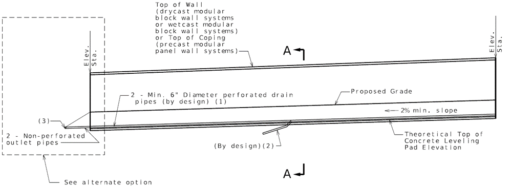 ELEVATION SHOWING DRAIN PIPE
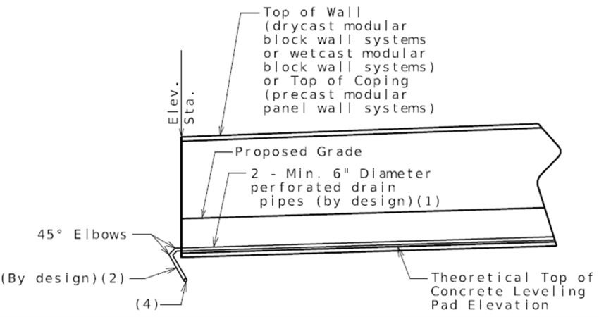 Alternate option

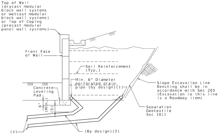 Section A-A
