751.34 Concrete Pile Cap Non-Integral End Bents
751.34.1 General
751.34.1.1 Material Properties
| Concrete | ||
|---|---|---|
| Class B Concrete (Substructure) | = 3.0 ksi | |
| = 10 | ||


Class B-1 Concrete (Substructure) may also be used in special cases (See Project Manager). The following equations shall apply to both concrete classes:
Modulus of elasticity,

Where:
- f'c in ksi
- wc = unit weight of nonreinforced concrete = 0.145 kcf
- K1 = correction factor for source of aggregate
- = 1.0 unless determined by physical testing
Modulus of rupture,
- LRFD 5.4.2.6

Where:
- f'c is in ksi
| Reinforcing Steel | ||
|---|---|---|
| Minimum yield strength, | = 60.0 ksi | |
| Steel modulus of elasticity, | = 29000 ksi | |


751.34.2 Design
751.34.2.1 Limit States and Factors
In general, each component shall satisfy the following equation:

Where:
| = Total factored force effect | |
| = Force effect | |
| = Load modifier | |
| = Load factor | |
| = Resistance factor | |
| = Nominal resistance | |
| = Factored resistance |


Limit States
The following limit states shall be considered for abutment design:
- STRENGTH – I
- STRENGTH – III
- STRENGTH – IV
- STRENGTH – V
- SERVICE – I
- FATIGUE
See LRFD Table 3.4.1-1 and LRFD 3.4.2 for Loads and Load Factors applied at each given limit state.
Resistance factors
- STRENGTH limit states, see LRFD 6.5.4.2 and LRFD 5.5.4.2
- For all other limit states, = 1.00
751.34.2.2 Loads
Dead Loads
Loads from stringers, girders, etc. shall be applied as concentrated loads applied at the centerline of bearing. Loads from concrete slab spans shall be applied as uniformly distributed loads.
Live Loads
Loads from stringers, girders, etc. shall be applied as concentrated loads applied at the centerline of bearing. Dynamic load allowance (impact) should be included for the design of the beam. No dynamic load allowance should be included for foundation design.
For wings with detached wing walls, no portion of the bridge live load shall be distributed to the detached wall. The detached wing wall shall be designed as a retaining wall. The weight of the barrier or railing on top of the wall shall be included in the dead load.
Collision
Collision shall be designed if abutments are located within a distance of 30.0 feet to the edge of roadway, or within a distance of 50.0 feet to the centerline of a railway track and conditions do not qualify for exemptions given in EPG 751.2.2.6. If designed for, the collision force shall be a static force of 400 kips assumed to act in any direction in a horizontal plane, at a distance of 4.0 feet above ground.
Temperature
The force due to expansion or contraction applied at bearing pads are not used for stability or pile bearing computations. However, the movement due to temperature should be considered in the bearing pad design and expansion device design.
Distribution of Loads
Wing and Detached Wing Walls
For seismic design category A: When Wing Length, L, is greater than 22'-0", use maximum of 22'-0" non-integral abutment wing wall combined with a detached wing wall.
Standard wing reinforcement is developed assuming a pinned connection at the bottom (tip) of wing. This assumption is applicable for cases where the passive pressure from the fill slope can be counted on to partially resist the active forces from the backfill. In a seismic event the forces on the wings are developed by the wings moving into the soil backfill and the fill slope resistance is less reliable. For seismic forces wings shall be designed assuming there is no lateral restraint at the bottom of the wing. The reduced restraint conditions require a more practical limit for the wing length.


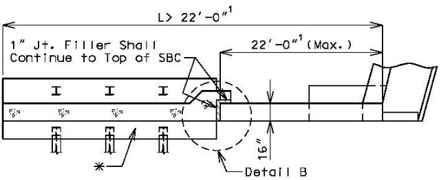
Section A-A
Detail B


| * | Detached wing wall shown is for illustration purpose only. Design detached wing wall as a retaining wall. |
| ** | Use retaining wall design. |
| 1 For seismic design category B, C and D only: The wing length shall not be greater than 17 feet. When a detached wing wall is required the non-integral abutment wing length shall not exceed 17 feet. | |
| Report Pile Cut-off Elev. and Minimum Galvanized Penetration (Elev.) (See EPG 751.50 Standard Detailing Note E2, (Foundation Data Table). |
751.34.2.3 Design Assumptions
| (1) | Beam |
| The beam shall be assumed continuous over supports at centerline of piles. One half of the dead load of the approach slab shall be included in the beam design. |
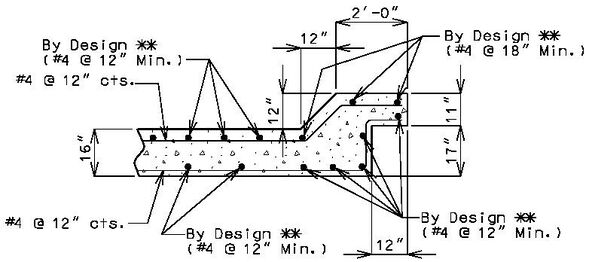
| (2) | Wing and Backwall | |
| (a) | Vertical Loads | |
| The minimum steel placed horizontally in wings shall be #6 bars at 8" centers, each face. These bars should be adequate to support the wing. See figure below. | ||

| Note: | The minimum steel (horizontally) in the corner haunch at the junction of the wing and backwall shall be #6 bars at 8" cts. " |

| (b) | Horizontal Loads |


751.34.3 Details
751.34.3.1 Front Sheet
| Notes: | The following are details and dimensions for the plan view on the Front Sheets. |
| Details for unsymmetrical roadways will require dimensions tying Centerline Lane to Centerline Structure. | |
| Pile arrangement shown is for illustrating dimensions and should not be considered as a recommended pile arrangement. |

751.34.3.2 Wide Flange Beams, Plate Girders and Prestressed Girders
For epoxy coated reinforcement requirements, see EPG 751.5.9.2.2 Epoxy Coated Reinforcement Requirements.
 | ||
| Expansion Device | No Expansion Device | |
|---|---|---|
 |

|
| Part Section at Centerline | End Elevation |
|---|
| (1) | When the total length of a beam and backwall exceeds 60'-0", use a keyed construction joint at or near CL bent as shown, preferably located at 1/4 point between piles. Maximum key length equals 18". For multiple keys make total key length equal to H/3 or d/3. |  |
| (2) | Slope top of beam one inch when using expansion devices. | |
| (3) | Wing layout length shall be rounded to the next higher foot. See the profile sheet for length of wing to fill face. | |
| (4) | See Design Layout for maximum slope of spill fill. | |
| (5) | Provide a minimum of 8" cl. from outside edge of pile to face of beam. | |
| (6) | Length determined by superstructure requirements or the minimum support length required for seismic criteria. | |
| (7) | Dimensions are based on a 2.0% sloped deck. Subtract 1/8” for a 3/16” per foot sloped deck. | |
| (8) | Based on 8 ½” slab. Adjust for different slab thickness. |

| |
| Expansion Device | No Expansion Device |
|---|---|
| Elevation | |
.jpg)
| |
| Expansion Device | No Expansion Device |
| Plan (Square) | |
| (*) End pile edge distance is to be 18” and provide a minimum of 8” clear from outside edge of pile to outside face of beam. | |
.jpg)
| |
| Expansion Device | No Expansion Device |
| Plan (Skewed) | |
| (*) End pile edge distance is to be 18” and provide a minimum of 8” clear from outside edge of pile to outside face of beam. | |
| Length determined by superstructure requirements or the minimum support length required for seismic criteria. |

|
| Square |
|---|

|
| Skews Thru 15° - Left Advance Shown |

|
| Skews Thru 15° - Right Advance Shown |
| (*) | When total length of beam and backwall exceeds 60'-0", show a keyed construction joint at or near the centerline of bent as shown, preferably located at the 1/4 point between piles. Unless required by design or stage construction, this construction joint shall be shown as optional on the plans and may be eliminated at the contractor's discretion. |

|
| Two Rows of Piles |
| Section Thru Bents |
|---|
| 3'-6" min. (1" Increments). Dimensions may be increased for superstructure requirements or the minimum support length required for seismic criteria. | |
| When this dimension is less than 6", make the front face vertical. | |
| Use 18" min. thickness. | |
| 4'-0" min. (1" Increments). | |
| Check clearance of anchor bolt well to top of pile. Increase beam depth, if needed. | |
| Slope top of beam 1" when using expansion device only. | |
| Apply protective coating to the backwall, top of beam cap and front face of beam cap when using expansion devices in accordance with Sec 711, Concrete Bents and Piers (Urethane or Epoxy). | |
| (*) | Provide a minimum of 8" clear from outside edge of pile to face of beam. |
| Note: | Pile arrangements shown is for illustrating minimum dimensions only and should not be considered recommended arrangements. |
.gif)
|
| Plan of Footing (Square) |
|---|
.gif)
|
| Plan of Footing (Skews Thru 15° - Left Advance) |
.gif)
|
| Plan of Footing (Skews Over 15° - Left Advance) |
| End pile edge distance is to be 18". Max. pile spacing = 12'-0". Pile spacing increments to be dimensioned as computed (1" increment). Provide a minimum of 8" clear from outside edge of pile to outside face of beam. | |
| Show on plans. For exceptions to these dimensions, see the Structural Project Manager. | |
| (*) | Provide a minimum of 8" cl. from outside edge of pile to face of beam. |
| Steel piles shown, CIP piles similar. | |
| Left advance shown, right advance similar. | |

| |
| Expansion Device | No Expansion Device |
|---|---|
| Bridges on Grade and Skew or Superelevated (With or Without Expansion Device | |

| |
| Expansion Device | No Expansion Device |

|
| Bridges With Expansion Devices |
|---|
| For epoxy coated reinforcement requirements, see EPG 751.5.9.2.2 Epoxy Coated Reinforcement Requirements. | |

| |
| Typical View of Beam | |
|---|---|

|

|
| Part Section A-A | Part Elevation |

| |
| Detail of Keyed Const. Joint | |
.gif)
| |
| Expansion Device | No Expansion Device |
|---|---|
| Part Plan (Skewed) | |
.gif)
| |
| Expansion Device | No Expansion Device |
| Part Plan (Square) | |

| |
| Expansion Device | No Expansion Device |
| Sections Near Left Wing | |
| Top of curtain wall shall not obstruct bottom of slab. If necessary slope top of curtain wall. | |
| Elevation A - | Wing elevation is determined at this point for bridges on grade. |
751.34.3.3 Wing Brace Details
The wing brace dimensions will only vary on the wing with obtuse angle. Wing brace dimensions shown are minimum dimensions. The wing with the acute angle will always be 18" minimum.

|
| Skews 0° thru 45° |
|---|

|
| Skews 45°00'01" thru 55° |

|
| Skews 55°00'01" and Over |
| Note: | Left advance shown, right advance similar. |
751.34.3.4 Exploded View of the End Bent

| Note: | Exploded view above is for information only. |
751.34.3.5 Vertical Drains
| Bridge Standard Drawings |
| Vertical Drain at End Bents |