233.2 At-Grade Intersections with Stop and Yield Control
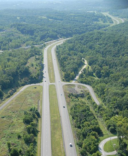
Each intersection has the potential for several different types of vehicular conflicts. The possibility of these conflicts actually occurring can be greatly reduced through the provision of proper geometry, sight distance and appropriate traffic control. The avoidance of conflicts and the efficiency of traffic operations still depend on the judgment, capabilities, and response of each individual driver.
Stopping sight distance is provided continuously along each roadway so drivers have a view of the roadway ahead that is sufficient to allow drivers to stop. The provision of stopping sight distance at all locations along each roadway, including intersection approaches, is fundamental to intersection operation.
The driver of a vehicle approaching an intersection must have an unobstructed view of the entire intersection, including any traffic control devices, and sufficient lengths along the intersecting roadway to permit the driver to anticipate and avoid collisions. The sight distance needed under various assumptions of physical conditions and driver behavior is directly related to vehicle speeds and to the resultant distances traversed during perception-reaction time and braking.
| Rural Expressway, Median Crossovers |
| Report 2001 |
| Report 2004 |
| Summary 2004 |
| Evaluation of J-turn Intersection Design Performance in Missouri |
| See also: Innovation Library |
Sight distance is also provided at intersections to allow the drivers of stopped vehicles sufficient view of the intersecting roadway to decide when to enter or cross it. If the available sight distance for an entering or crossing vehicle is at least equal to the appropriate stopping sight distance for the major road, then drivers have sufficient sight distance to anticipate and avoid collisions. However, in some cases, this may require a major-road vehicle to stop or slow to accommodate the maneuver by the minor-road vehicle. To enhance traffic operations, intersection sight distances that exceed stopping sight distances are desirable along the major road.
233.2.1 Intersection Sight Distance Criteria
| Stopping sight distance is the length of the roadway ahead that is visible to the driver. The available sight distance on a roadway should be sufficiently long to enable a vehicle traveling at or near the posted speed to stop before reaching a stationary object in its path. Although greater lengths of visible roadway are desirable, the sight distance at every point along a roadway should be at least that needed for a below-average driver or vehicle to stop. |
| Stopping sight distance is the sum of two distances: |
| - The distance traversed by the vehicle from the instant the driver sights an object necessitating a stop to the instant the brakes are applied and |
| - The distance needed to stop the vehicle from the instant the brakes application begins. |
| These are referred to as brake reaction distance and braking distance, respectively. |
| Intersection sight distance is the distance the driver of a vehicle approaching an intersection needs to have an unobstructed view of the entire intersection, including any traffic control devices, and sufficient lengths along the intersecting major roadway to permit the driver on the approaching roadway to anticipate and avoid potential collisions. The sight distance required for various conditions and driver behaviors is directly related to vehicle speeds and resulting distances traversed during perception-reaction time and braking. |
The minimum sight distance for at-grade intersections, entrances, and median openings, measured along the centerline of the main road, is equal to the intersection sight distance based on the operating speed of the main road. This distance is based on a 7.6 ft. eye height for trucks, and a 3.5 ft. eye height for passenger cars. The object height is 3.5 ft. for all vehicles. The minimum sight distance at all grade intersections measured along the minor road, is the stopping sight distance based on the operating speed of the minor road. Exceptions are sometimes necessary where the minor road is being improved to intersect a more important road. Where the more important road is being improved, the minor road is located or improved as required to obtain the required sight distance. If the operating speed of the minor road is not known, a speed of 30 mph is used. Grades are determined and access points are located to provide the required sight distance as well as achieve the necessary spacing requirements contained in the Permits and Access Requests. Minimum values for stopping sight distance are described in EPG 230.2.5 Stopping Sight Distance and K Factors. Intersection Sight Distance for a passenger vehicle is based on the stopped vehicle turning left onto a two-lane roadway with no median and grades of 3% or less. Intersection Sight Distance for a combination truck is based on the stopped vehicle turning left onto a two-lane roadway with no median and grades of 3% or less. These sight distance requirements ensure that intersections and access points are visible to approaching traffic. Additional guidance is available in the 2004 AASHTO Green Book (see "Intersection Control" in Chapter 9) for mutli-lane roadways or when grades exceed 3%.
A triangle of right of way is acquired for required sight distance and visibility at all state route and local road intersections, except where the normal right of way will provide the equivalent of the triangle of right of way. The triangle is graded to the elevation of shoulder point to shoulder point of intersecting roads, to provide the sight distance when the intersection is in a cut. The backslope is graded to the normal cut slope used on the project for the main roadway. Controlled access right of way at intersections for otherwise normal access routes is provided at all state routes and all side roads that intersect a state route carrying over 1700 ADT in the design year.
The dimensions for the additional triangle of right of way, where required, are determined by connecting points on the centerline of the intersected roadways a distance "d" from the point of intersection, as tabulated in the above table. Where grading is required to provide sight distance, additional right of way may be necessary to provide room for the grading. The operating speed of each intersecting road is used to determine "d". For side road approaches where the operating speed is unknown, an assumed speed of 30 mph is used. The right of way is dimensioned in 5 ft. increments by scaling.
Table 233.2.1 Intersection Sight Distance
| Speed (mph) | Intersection Sight Distance, Passenger Vehicle (ft.) | Intersection Sight Distance, Combination Truck (ft.) | Length Of Leg, “d” (ft.) |
|---|---|---|---|
| (Eye Ht. = 3.5 ft.; Object Ht. = 3.5 ft.) | (Eye Ht. = 7.6 ft.; Object Ht. = 3.5 ft.) | ||
| 30 | 335 | 505 | 140 |
| 35 | 390 | 590 | 165 |
| 40 | 445 | 675 | 195 |
| 45 | 500 | 760 | 220 |
| 50 | 555 | 870 | 245 |
| 55 | 610 | 930 | 285 |
| 60 | 665 | 1010 | 325 |
| 65 | 720 | 1090 | 365 |
| 70 | 775 | 1180 | 405 |
The values in this table are based upon Exhibits 9-55 and 9-56 of the 2004 AASHTO Green Book.
233.2.2 Median Openings
Median openings for public use are considered at the intervals outlined in the Access Management Guidelines. Priority is given to the spacing of the openings for state routes, county roads, and major streets. Details for median openings are shown in the Standard Plan 203.50. Maintenance and emergency median openings (i.e. crossovers) are constructed by district maintenance forces and are not included in the design plans.
Objectives for a median opening include:
- Reducing accidents including both frequency and severity,
- Accommodating the appropriate design vehicle,
- Accounting for passenger vehicles,
- Minimizing driver confusion,
- Providing adequate guidance,
- Decreasing undesirable driver behavior (such as side-by-side queuing) and
- Providing proper balance between mobility and accessibility.
Proper selection of the design for the median opening will provide many years of quality service.
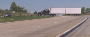
A greater proportion of fatal crashes occur at non-signalized expressway intersections (median openings) when compared to two-lane roadway intersections. Inadequate vehicle placement has caused operational concerns (even at low volumes), such as side-by-side queuing and sight distance restrictions. The inability of a median opening to adequately accommodate the WB-67 design vehicle is evidenced by off-track rutting. The WB-67 is longer than the existing standard 60 ft. median width. Traditional treatment for large vehicle off tracking has been to simply add pavement to the areas where off tracking has occurred. This has added to inadequate vehicle placement by providing a “sea of pavement” with no directional guidance to vehicles. This has not been an effective solution at median openings.
For most types of median openings, the mainline volume, speed and percent of trucks is not a deciding factor. The biggest design consideration is the crossroad volume. The only exception to this is the Type 1 median opening, which provides no place for turning vehicles to decelerate. In this instance, the mainline volume contributes to the number of accidents at the location.
The designer will first consider providing access to only the nearest lane (right-in/right-out) during the development of the design of the expressway. If this is not adequate, then other solutions must be developed.
The presence of heavy truck volumes will determine design elements such as median width and minimum radius. Based on these volumes, the median width at the median opening location may need to be wider than the rest of the length of the road. For example, most expressways are designed for a 60 ft. median, but in order for a large truck to completely cross one set of lanes and wait in the median for a gap to cross or turn into the other set of lanes, the required median width would be 84 ft. Building an entire project with an 84 ft. median to provide adequate width only at crossroads is excessive.
All median openings must be designed to accommodate the appropriate design vehicle. The decision to accommodate the WB-67 design vehicle is based on the number of trucks and the presence of large truck generators. There are many methods of accommodating the WB-67 besides simply widening the roadway. Truck aprons are to be considered where appropriate. The pavement design for an apron depends on the amount of anticipated truck traffic. If this traffic exceeds 200 trucks per day, the thickness (and mix type) of the apron should be the same as the mainline. If this traffic is less than 200 trucks per day, the thickness of the apron should be 8 inches of PCCP or 11 inches of HMA (using the same mix types as the mainline).
Horizontal and vertical alignment of the expressway and the crossroad will impact the design of the median opening, especially sight distance. The cost associated with a particular location may influence the type selection. For example, if the two sets of lanes have different vertical elevations, it may be economical to consider a partial interchange that takes advantage of the elevation differences rather than to widen the median to accommodate the grades for an at-grade crossing.
The need for future expansion must be considered in median opening type selection and design to ensure an appropriate level of flexibility exits for future upgrades. The project must never be overbuilt today on the promise that traffic volumes will grow. However, planning for known future growth is always something that must be considered.
The impacts of special traffic generators, such as schools, retail development or big box stores are considered for all types of median openings. In these instances it may be necessary to alter the design or use an entirely different type of median opening to address the special needs of the generator.
Finally, long roadway corridors need to be viewed in the context of maintaining a high level of overall consistency. While it is not necessary each median opening on a route be identical, if there is a choice to be made between two types, consistency within the corridor is desirable. However, it is much more important the right median opening type is used even if each median opening is different.
The following table provides subjective ratings for public acceptance, driver expectations and safety. Each median opening type has been rated from 1 to 5 (i.e. lowest to highest, or worst to best) rather than simply showing data. For example, the safety scale reflects the number of conflict points existing in the intersection area; this influences accident severity and frequency.
| Category | Type 1 No Turn Lanes |
Type 2 Turn Lanes | Type 3 Offset Lefts | Type 4 Median U-Turn |
Type 5 Partial Grade Separated Interchange |
Interchange | |
|---|---|---|---|---|---|---|---|
| Operations | Mainline Volume | Conflicts can create rear-end crashes | Not a Primary Factor | Not a factor in selection but a factor in design | Not a Primary Factor | ||
| Crossroad Volume | < 10 | < 2,000 | < 3,000 | < 4,000 | > 3,0001 | > 4,000 | |
| Indirect Turning Movements | None | Some | None | None | |||
| Site Conditions | Recommended Median Width | 60 feet | 80 feet | N/A | |||
| ROW Impacts | Low | Medium | High | High | |||
| Public Involvement | Driver Expectations (1 does not meet, 5 meets) |
2 | 5 | 4 | 2 or 3 | 3 | 5 |
| Public Acceptance (1 low, 5 High) |
3 | 5 | 4 | 2 or 3 | 4 | 5 | |
| Safety Scale (1 Low, 5 High) |
1 | 2 | 3 | 4 | 4 | 5 | |
| Cost Magnitude ($1,000)2 | 40 - 50 | 100 - 150 | 150 - 200 | 100 - 250 | 2,500 - 3,500 | 5,000 - 8,000 | |
Notes:
- 1. Insufficient data to determine upper threshold for Type 5 volumes.
- 2. Cost Assumption: 60 ft wide median on new construction. Does not include right turn-lanes of R/W acquisition.
When an interchange on a roadway is not warranted, MoDOT must adequately explain to the public why choosing the type of median opening provides a safe and long-term solution to their traffic needs. Public meetings can provide sketches and traffic modeling to adequately explain how the facility will operate. This approach has been successful nationwide with public acceptance of a project increasing from low to high.
Median openings on expressways are classified in one of five types. Each type has particular advantages and disadvantages. The selection of a particular type of opening at a location on an improvement project must receive thorough consideration.
233.2.3 Type 1: Median Opening Without Left Turn Lanes
The Type 1 Median Opening has very limited application. Normally, a median opening is not provided for a field entrance or private road, but if an opening is allowed, the Type 1 may be considered. A Type 1 median opening is not normally used for a commercial entrance.
Since the Type 1 does not have a left turn lane, vehicles must slow down in the “passing” lane of the expressway. The potential for a high-speed rear end crash is high. Therefore, these median openings are only considered when the entrance has very low traffic volumes (less than 10 vehicles per day).
Advantages
- Allows for all turning movements at the crossover
- Low cost
Disadvantages
- Vehicles must slow to turning speeds in the passing lane of the expressway
- Because there are no turn lanes, the opening is not easily identified by drivers
- Side-by-side queuing of vehicles within the median (undesirable vehicle placement) often occur
- Vehicles within the median and those vehicles approaching the median can create sight distance restrictions
- 18 conflict points
- Difficult to accommodate the WB-67
Additional Items to Consider
- If large vehicles are expected to routinely use the median opening, accommodations are necessary:
- 84 ft minimum median width
- Off-tracking aprons
- Right-In/Right Out access to the nearest lane is preferred to providing a Type 1 median opening
| Rural Expressway, Median Crossovers |
| Report 2001 |
| Report 2004 |
| Summary 2004 |
| See also: Innovation Library |
233.2.4 Type 2: Median Opening with Left Turn Lanes
The Type 2 Median Opening is the most commonly used. These median openings usually experience safety issues before their capacity is exceeded. Based on crash experience from Missouri and other national studies, when crossroad volumes are less than 1000 vehicles per day (VPD) they typically operate in a satisfactory manner. As volumes on the crossroad approach 2000 VPD, safety issues usually become more pronounced.
This type of median opening may be supplemented with other design strategies (deceleration lanes, acceleration lanes, truck aprons, wide medians, etc.) based on traffic and geometric site conditions.
Advantages
- Allows for all turning movements at the crossover
- Adaptable to a wide range of median widths
- Can retrofit an existing Type 1 median opening without purchasing additional right-of-way.
- Missouri drivers are very familiar with this design
- Medium to low in cost
- Drainage easily addressed
Disadvantages
- Vehicles turning left from the mainline and vehicles using the median opening from the side road can create vehicle placement confusion (ie. who has the right of way)
- Vehicles within the median and those vehicles approaching the median can create sight distance restrictions
- Side-by-side queuing of vehicles within the median (undesirable vehicle placement) can occur
- A designer will not consider including signalized intersections for expressways, although one may be installed at an existing location with the recommendation of the Highway Safety and Traffic Division. The Type 2 median opening requires additional geometric improvements before signals can be installed and effectively operated
Additional Items to Consider
- If large vehicles are routinely expected to use the median opening, the following accommodations must be made:
- 84 ft minimum median width
- Off-tracking aprons
- Provide adequate deceleration length for the left turn lanes to minimize the speed reduction required of vehicles in the “passing” lane that intend to use the median opening
- Right turn deceleration lanes may be needed based on traffic volumes. Offsetting the right turn deceleration lane is preferred unless geometric conditions actually decrease the sight distance
- Median acceleration lanes can be used to provide traffic (i.e. trucks) an opportunity to accelerate before attempting to enter the traffic stream. Median acceleration lanes also provide trucks entering the main roadway from the side road a place to accelerate so they do not have to “fit” into a 40 ft. or 60 ft. median.
233.2.5 Type 3: Offset Left Turn Lanes
The Type 3 Median Opening provides offset left turn lanes at expressway median opening to reduce the frequency of right angle and rear end accidents. This applies to expressway intersections with medians wide enough to accommodate the offset turn lanes.
Advantages
- Allows for all turning movements at the crossover
- Serves more left turns than Type 1 or Type 2 Median Openings
- Improves sight distance for mainline left turning traffic
- Reduces the number of high-speed conflicts and the risk of severe crash types (i.e. right angle collisions)
- Improves the angle of view, allowing drivers to more effectively use available gaps
- Separates left turning traffic from the mainline roadway
- Addresses side-by-side queuing by keeping left turning traffic separated from those entering the median from the sideroad
- Less confusion in the median opening, paths are defined more clearly than the Type 1 or 2 Median Opening designs
- Adaptable to a wide range of median widths
- Can retrofit an existing median without purchasing additional right of way and can add a signal without major geometric improvements
- Reduces the number of conflict points
Disadvantages
- Drivers may be unfamiliar with this type of intersection
- Mainline left turning traffic must enter the median sooner than expected
- Possible additional drainage and/or pavement requirements
Additional Items to Consider
- Design of offset-left turn lane
- - Parallel lane is necessary to provide motorists enough time to react and move into the left turn lane area; 100-200 ft. is an adequate length for the parallel lane
- - Storage and deceleration lengths shall be calculated according to each location’s traffic characteristics
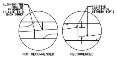
- - It is recommended to provide “positive separation” between the edge of pavements of opposing left turn lanes, as depicted in the drawing below. Having them lined up can, during nighttime, give motorists the false appearance that the lane continues through the median and may lead them to not stop in time.
- Accommodating WB-67 trucks or other large vehicles
- - AutoTurn software should be used to simulate the path and off-tracking of WB-67s or other large vehicles that are expected
- - 84 ft. minimum width is necessary to allow a truck to fit in the median
- - Provide paved aprons for off-tracking to prevent rutting
- - If allowing U-turns, may need to modify sideroad geometrics to make U-turn successful for a WB-67
- - Median acceleration lanes also provide trucks entering the main roadway from the side road a place to accelerate, so they do not have to “fit” into a 40 ft. or 60 ft. median.
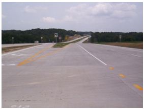
- Recommended options for the triangular area
- - Pave entire area and stripe with chevron pattern

- - Pave half and stripe with chevron pattern. Grass or rock the rest
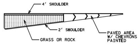
- - Grass or rock the entire area and include lighting. Without the additional pavement and striping that the other two options offer, there is not adequate delineation at night, so therefore lighting is required.
- - Consider giving options in the contract as to how this triangular area could be constructed to promote lower bids
- Signing and striping considerations
- - It is important to clearly mark and sign the intersection. Refer to EPG 903.17 Typical Signing Applications for signing.
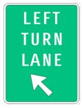
- - If the crossroad is a city or county road, it is recommended to install the following left turn lane sign at the beginning of the offset left taper:
- It is also recommended to install an advance intersection guide sign, for example:
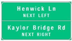
- - Consider using decision sight distance (refer to Table 3-3 in AASHTO's A Policy on Geometric Design of Highways and Streets 2011, the "Green Book") as guide for placing advanced intersection guide signs before the left turn opening
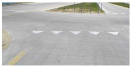
- - Using painted “shark’s teeth” yield bar at the end of the left turn lane
- - Using left turn arrows on the pavement of the offset left turn lane
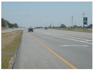
- - Using “dotted” edgeline extensions across the intersections to provide guidance for motorists in the median as to where to stop
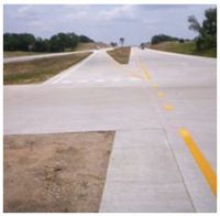
- Public information and education programs concerning the operation of offset left-turn lanes and their safety benefits must be considered when these treatments are used for the first time in a given area
233.2.6 Type 4: Directional Median Opening with Downstream U-Turns
| Univ. of Missouri's Evaluation of J-turn Intersection Design Performance in Missouri |
Although variations of the directional median opening with downstream median U-Turn design, sometimes called a “J-Turn”, have been used in the United States since 1960, this concept is new to Missouri. The Type 4 Median Opening, (J-Turns or J-Turns for significant truck volumes with limited gap times, or steep grades), eliminates some or all traffic movements through the median. Traffic on the sideroad is forced to turn right onto the main roadway rather than go straight through the median. Through and left turn movements from the sideroad are completed through a downstream median U-Turn located approximately 600-1000 ft. from the primary intersection. When the median U-Turn is located close to the crossroad, the benefit of reducing right angle crashes is limited. Additionally, a close spacing can also force vehicles to make quick weaving movements at speeds slower than those of the through traffic. The specific location of the median U-Turn is determined by a capacity analysis which includes anticipated weaving movements. The Highway Capacity software and VISSIM are useful in this analysis.
Typical signing details are found in Figure 903.13.26 Typical Signing for Type 4 Median Openings and in Figure 903.13.27 Signing for Type 4 Right-In, Right-Out Openings.
Michigan, Florida, Maryland, and North Carolina currently use geometric designs that restrict some or all turning movements at the primary intersection and provide for downstream U-Turns. These treatments are primarily used in urban rather than rural areas in Michigan and Florida. Also, the “Michigan U-Turn” is usually signalized with the secondary through movements using the normal intersection path.
Advantages
- Reduces crash potential, especially for high severity right angle crashes (conflicts points are reduced to 4). Left and through movements from the sideroad are completed by a two-stage merging movement as opposed to a one stage crossing movement.
- Can accommodate approximately two-times the sideroad volume as compared to the traditional (i.e. Type 2) median crossover type. Typically, it operates effectively for sideroad volumes up to 2,000 VPD and can function for volumes up to 4,000 VPD, depending on site-specific conditions.
- May be easily retrofitted from a Type 1 and Type 2 median opening (depending on site conditions) without purchasing additional right-of-way.
- Low to medium cost
- A designer is not to consider including signalized intersections for expressways, although one may be installed at an existing location with the recommendation of the Highway and Safety Traffic Division. This type of median opening can efficiently be retrofitted with traffic signals.
Disadvantages
- Most drivers (including typical Missouri drivers) are not familiar with this design
- Requires extraordinary signing and public education efforts
- Creates adverse travel; some movements are indirect
- Creates mainline weaving movements
Additional Items to Consider
- Not to be used with median widths less than 60 ft.
- This median opening is a flexible design and may be supplemented with other design strategies (acceleration/deceleration lanes, wide medians, etc.) based on site-specific traffic and geometric conditions. For instance, median acceleration lanes can be used to provide traffic (i.e. trucks) an opportunity to accelerate before attempting to enter the main roadway traffic stream.
233.2.7 Type 5: Partial Grade Separated Intersection
A Type 5 Median Opening, or Partial Grade Separated Intersection, is considered a hybrid of two common types of median openings]; the traditional diamond interchange for one direction of traffic, and a Type 2 median opening with median acceleration/deceleration lanes for the opposing direction of traffic. Since this type of median opening is essentially an interchange involving construction of a bridge structure, providing it at a rural expressway location must be only considered when less costly alternatives have been exhausted as the result of safety concerns and capacity issues. This type of median opening can be used as a low cost alternative for a “trumpet” style interchange.
This type of median crossing is used to eliminate the frequency of collisions between left turning and opposing through vehicles, as well as rear-end crashes of vehicles traveling in the same direction. This crossing can be used for any expressway intersection but is best suited to “T” type intersections where the crossroad traffic volumes exceed what is considered acceptable for traditional “at-grade” intersections.
Advantages
- Allows for all turning movements at the crossover
- Minimizes potential for severe right angle crashes
- Provides a wider median for long vehicles, such tractor-trailer trucks
- Separates left turning traffic from the mainline roadway
- Has less right-of-way impact than a full diamond or trumpet interchange
- Cost is significantly less than a traditional diamond interchange
- A blend of two familiar configurations satisfies driver expectation
- Could retrofit an existing median crossing without purchasing additional right-of-way, if existing terrain is acceptable (i.e.: profile of one lane is higher than other)
Disadvantages
- Cost – bridge structure, additional grading, pavement, and right-of-way
- Right-of-way impacts are higher than with an at-grade intersection
- On straight alignments a median flare is required to accommodate the grade separation; thus introducing horizontal curvature
- The possibility of additional drainage requirements near the bridge
Additional Items to Consider
- Public information and education programs must be considered concerning the operation of the Type 5 median opening including the resultant safety benefits when this treatment is used for the first time in an area
- Additional signage is necessary to avoid driver confusion and thus prevent the motorist from entering the wrong roadway against opposing traffic, especially on the at-grade intersection side
- Develop detailed guidelines and parameters for use and application
- Instruct designers on the proper application of this type if intersection
If a median opening is to be constructed of portland cement concrete, the plans will show the joint layout. To avoid sympathy cracks in the travelway, it is desirable to match median opening joints with the adjacent travelway joints and avoid specifying a median opening joint that will intersect the adjacent travelway where no joint exists. It is acceptable for joints in the centerline of the median opening not to match directly. Additional information concerning pavement joints can be found in the Pavement article.
233.2.8 State Routes and Important Roads and Streets
Highways are designed to provide for the safe, efficient and economical transportation of persons and goods. The success of a design is dependent on proper planning, geometric design, and efficient traffic operations. The following paragraphs only discuss general requirements. Variations required by location and local conditions will usually offer an infinite number of solutions for specially designed at-grade intersections.
Designs for important side road intersections are based on a volume product. For volume products equal to or greater than 700,000 the design shown on Standard Plan 203.65 is used. For volume product intersections less than 700,000, see Standard Plans 203.62. The volume product is the product of Vm x Vc. Vm is the design AADT on the major approach (one direction volume for divided and both direction volume for 2-way). Vc is the design AADT on the minor approach. Additional information concerning intersection design can be found in the Access Management Guide.
Efficient traffic operation is dependent upon geometric design. It is desirable this design considers traffic signal control as a design criterion at all intersections where traffic conflicts are present. When this is not done and traffic signal control becomes necessary, the net result is signals are poorly located with respect to driver vision, disregarded protected left turning movements, and other necessary requirements for efficient traffic signal control compromised or forgotten.
Grades are designed in accordance with vertical alignment criteria.
Schematic details for grade intersections are indicated on the preliminary plan, along with traffic data, including turning movements. Approval of the preliminary plan constitutes approval of the schematics of the intersections.
233.2.9 Roadway Approaches
The location and design of approaches affect the safety and traffic handling capacity of the highway. Therefore, the location and design of each feature receives careful consideration. Each approach is designed with appropriate width and radii that will permit entry of the design vehicle without encroachment on opposing traffic lanes. Access Management Guidelines will be used to determine the number, the location and the spacing requirements for approaches and driveways.
Direct access is not allowed to the through lanes on freeways since they are designed with full control of access. Access Management Guidelines are used to determine the number of access points provided on all other facilities (i.e. controlled access and normal right of way).
| Additional Information on Driveway Maintenance |
| Maintenance of Residential, Commercial and Public Road Entrances |
233.2.10 Driveway and Approach Pavement Design Criteria
Driveways are designed in accordance with the details shown on the standard plans. The grade controls are followed if at all practicable. Driveway and approach pavement thickness shall be a minimum of 5 ¾ in., using one of the following: 1 ¾ in. BP-1 on 4 in. PMBB or jointed plain concrete without dowels. The Construction and Materials Pavement Section should be consulted for actual design thicknesses.
233.2.11 Capacity
The appropriate capacities for at-grade intersections without signals are given in the following table. A more detailed capacity analysis is made as outlined in the Highway Capacity Manual, to determine the exact needs and requirements for the intersection.
| 2-Lane through Highway | 400 | 500 | 600 |
| Crossroad | 250 | 200 | 100 |
| 4-Lane through Highway | 1000 | 1500 | 2000 |
| Crossroad | 100 | 50 | 25 |
233.2.12 Islands
Islands are triangular or longitudinal. Triangular islands are generally used on the minor approach to an at-grade intersection, crossovers for major side roads, state routes and major streets, and on ramp terminals at the crossroad or streets at interchanges. Islands at ramp termini are placed in accordance with alignment controls of diamond interchanges. Islands for at-grade intersections are placed in accordance with Standard Plan 203.65. Islands when required at crossovers are placed in accordance with the standard plans. Where the highway shoulder is carried through the intersection, the island is placed at the edge of the shoulder. The side of a longitudinal island adjacent to through-traffic lanes is offset from the edge of the traveled way by at least 2 ft. The island may be offset a greater distance if necessary or desirable to eliminate a particular hazard.
There are two primary types of islands. They are:
Divisional Islands These are normally longitudinal islands used to divide opposing traffic to positively restrict encroachment by vehicles. They are at least 4 ft. wide and 12 ft. long. Preferably, they are 20 ft. in length. A divisional island nose is offset a minimum of 4 ft. from the projected edge of the travelway of the crossroad or street. Use AutoTurn to verify placement from turning vehicles. Divisional islands are always constructed with barrier type curbs and basic lighting is provided to the extent necessary to illuminate the ends of the islands. Examples of divisional islands are
- short bulb-type median islands used to provide protected left turn movements,
- all islands between opposing traffic streams,
- all islands established for the purpose of locating traffic signal poles or lighting poles.
Channelizing Islands These islands are used to guide and direct same direction traffic streams or diverging traffic streams. Channelizing islands may consist of painted areas, flush sodded areas, or raised islands. The islands are at least 75 ft2 in area or about 10 ft. on a side. Where raised channelizing islands are used, they are constructed with mountable type curbs. Channelizing islands are not lighted except when lighting is justified by other warrants. Examples of channelizing islands are those established for:
- guiding parallel or diverging traffic streams
- locating small signs
- providing pedestrian refuge
- reducing large paved areas at intersections.
When it is unclear what type of island is necessary, the island is classed channelizing to eliminate the need for lighting. In those cases where it is apparent that traffic signals will be installed within a reasonable period of time after construction at the intersection or interchange, divisional islands will be designed and lighted (by direct reflectance) with the initial construction. Additional information about islands is given in Chapter 9 of the AASHTO Green Book.
233.2.13 Auxiliary Lanes
Auxiliary lanes are provided on the major roadway and are encouraged on the minor roadway where possible to allow turning vehicles to slow and be stored out of the through traffic lanes. It is desirable to provide them since they improve safety, improve intersection capacity, and allow for the most efficient methods of controlling traffic. Often, auxiliary lanes can be added by utilizing existing shoulders. Consult the Access Management Guidelines for additional auxiliary lane information.
233.2.14 Length of Auxiliary Lanes
The length of a full width auxiliary lane consists of a deceleration length plus a storage length. Storage length is determined on the basis of the maximum possible total time cycle, peak hour traffic volume, and average storage length required per vehicle.
The length necessary is calculated by multiplying the average length required per vehicle (both trucks and cars) times the number of vehicles arriving per time cycle in the peak hour and is determined by the formula:
Where:
- L = length, ft.
- vph = vehicles per hour (design peak hour)
- cl = cycle length in seconds (use 120 seconds for unsignalized locations)
- PC = passenger cars, pickup and panel trucks
- TK = single unit or combination tractor trailer trucks and buses
- % = percent as a whole number
233.2.15 Deceleration Length
Deceleration distances (distances provided in the table reflect a 10 mph speed reduction) include minimum and desirable lengths and are provided where practical.
The desirable deceleration length represents the length required for a driver to react to a forming queue at an upcoming intersection and apply the brake coming to a stop behind the forming queue. This is a conservative approach. The minimum deceleration length represents only the braking distance required to come to a stop with a more aggressive deceleration rate. This is the less conservative approach. Table 3-1 of the AASHTO Green Book can be consulted for specific deceleration rates while Table 3-2 can be consulted (to determine increases in deceleration rates due to grades) for roadway grades equal to or exceeding 3%.
233.2.16 Required Storage Length
The required storage length for use in design is 1.5 times the calculated storage for major streets and 2.0 times the calculated storage for freeway off-ramps. A 50 ft. minimum storage length is desirable.
The calculated required length may be varied, when necessary, to provide a practical design consistent with capacity limiting features of the street approaches beyond the limits of the proposed improvement or with the unavoidable conflicts with other traffic movements on the same approach.
233.2.17 Left Turn Lanes
Left turn lanes are considered on roadways where traffic volumes are high enough or safety considerations are sufficient to warrant them. Access Management Guidelines are used to determine if left turn lanes are warranted. Where the peak hour left-turning traffic exceeds 300 vph, dual left turn lanes are considered. If the peak hour left-turning traffic exceeds 600 vph, a three lane left turn facility is considered. Left-turn lanes may also be considered at intersections with poor visibility or a history of crashes. Left-turn lanes are at least 10 ft. wide with additional width provided for striping of flush medians or for curb clearances of barrier curbs for raised medians. Left-turn lanes for 30 or 40 mph operating speeds are developed according to certain minimum transitions and are constructed using barrier curbs. They are lighted by direct reflectance (see EPG 901 Lighting) to the extent necessary to illuminate the ends. Left-turn lanes for 50 or 60 mph operating speeds are also developed according to minimum transitions. Left-turn lanes developed from continuous medians are constructed with barrier curbs for at least the length of the left-turn storage with the barrier end lighted by direct reflectance. Additional information concerning storage length is discussed later in this article.
The use of a divisional island at an intersection to separate the left turning traffic from same direction through traffic may be desirable, particularly where opposing traffic is separated by a wide median. This island will make a left turn from an auxiliary left turn lane mandatory and requires lane control signing.
At an intersection with multiple left-turn lanes, two or three vehicles will be simultaneously making left turns. Therefore, the number of receiving lanes on the downstream roadway will be the same as the number of left-turning lanes. Sometimes at an intersection with multiple left-turn lanes, the number of receiving lanes on the downstream roadway may be one less. In this situation, a multiple left turn may be installed by including a transition section on the receiving roadway, essentially creating a merging section with a lane-drop condition at another location downstream.
The distance measured from the beginning of the departing roadway to the beginning of the lane-drop location, excluding the lane-drop taper section, is known as the Merging Section Length. This length must be sufficiently long to avoid any delay to the left turning and through vehicles on the approach. When this length is insufficient, vehicles traveling on the lane being dropped will be forced to slow, stop or perform an unsafe maneuver. This results in undesirable traffic operations and safety problems, caused by queues overflowing into the intersection. A microsimulation analysis, using the VISSIM software package, is performed to determine the appropriate downstream lane-drop distance to avoid disruption of traffic.
The analysis requires the following data:
- Intersection movement volumes
- Percentage of heavy vehicles
- Operating speed of intersecting roadways
- Signal timing plan (including left turn green time)
- Intersection geometry (including left turn length)
- Expected lane distribution in the left turn lane(s) (observed or predicated percentage of vehicles using each left turn lane prior to the transition section in anticipation of the lane drop)
- The location and turning movement information of any driveways located in the Merging Section (including a driveway that is the destination of the lane-drop).
The analysis will also compare delay for left turning vehicles in the Merging Section for varying Merging Section lengths. The length that produces the optimum delay is selected.
233.2.18 Right Turn Lanes
Warrants for right turn lanes are determined by the Access Management Guidelines. To prevent through vehicles from being falsely led into the auxiliary right turn lane, an abrupt taper is used at the beginning of the lane. At locations where it is either impractical or not warranted to provide an auxiliary right turn lane, a channelizing island will reduce right turning maneuver conflicts with through traffic. However, a few straight through vehicles stopped in the right lane waiting for a gap in traffic will block the right turn movement. Conversely, a few right turning vehicles stopped while waiting for a gap in the cross street traffic will block the right lane for through vehicle storage.
With certain geometric conditions, it may be desirable to offset the right turn auxiliary lane for safety reasons. Offset right turn lanes can reduce severe right angle crashes by allowing crossing vehicles an unobstructed view of through traffic.
233.2.19 Median Acceleration Lanes
It may become necessary to provide a left hand acceleration lane along the median side of a four lane divided expressway downstream of a median crossover. Use of this lane is not “typical” and must not be viewed as an acceptable addition to all median crossings throughout the state. In the event a core team determines the provision of such an acceleration lane is warranted, notification must be submitted to the Highway Safety and Traffic Division, prior to the completion of the plans.
The following warrants shall be used to establish the need for a median acceleration lane:
- There is accident history at a specific expressway intersection. Of particular concern are right angle, sideswipe, and rear end accidents involving trucks.
- There is a high percentage of truck traffic originating on the minor roadway. Additionally, these trucks are of such length they cannot be accommodated within the median opening of the expressway.
- There is poor sight distance at the location that does not provide sufficient time for a motorist in the passing lane of the expressway to avoid a slow moving truck in the passing lane downstream of the median crossover.
- There are limited gaps available in the major road traffic stream.
The median acceleration lane must be sufficiently long to permit acceleration of trucks to the 85th percentile speed for vehicles operating on the expressway. The acceleration lane must have a total width of 14 ft. with sufficient striping to denote a lane width of 12 ft. with a 2 ft. offset from the left through lane. A 4 ft. wide shoulder must be provided on the median side of the acceleration lane.
233.2.20 Turning Radii
Minimum design vehicle turning radii are shown in the following table. These radii are satisfactory as minimum design where turning speeds of 10 mph or less are appropriate at intersections. The radii for turning movements at urban street intersections can be less where the extra pavement width serves to increase the useable radius. When curbs are used, it is desirable to use flatter curves than those in the minimum edge of traveled way designs.
The choice of minimum design for intersection radii is given in Chapter 9 of the AASHTO Green Book. This identifies the turning radii used for the design of various roadway facilities and the type of design vehicle to use as the control. Turning paths are checked using AutoTurn software for all allowed movements from each approach, to verify that the design vehicle can be accommodated. Best practices for use of AutoTurn include:
- Turn from center of lane to center of lane
- Use steer radius of 75 ft. for merging right turn
- Use steer radius of 50 ft. for yielding right turn
- Use steer radius of 50 ft. for left turn
The WB-67 (WB-20) is used as the design vehicle for geometric radii for ramp terminals on the interstate and primary system, as well as for adjacent outer roads and entrances where it is anticipated this vehicle will operate. This design vehicle is the maximum semitrailer (53 ft trailer length) able to legally operate in Missouri.
| DESIGN VEHICLE | MINIMUM SIMPLE TURNING RADIUS (ft.) | Edge of Traveled Way Design Simple Curve Radius (ft.) (Based on 90 degree Turn) | |
|---|---|---|---|
| Passenger Car | 24 | 30 | |
| Truck | 42 | 50 | |
| School Bus (S-Bus 40) | 39.4 | - | |
| City Bus | 42 | - | |
| Intermediate Semi Trailer(WB-50) | 45 | 60’ w/4.0’ offset & 15:1 Taper | |
| Interstate Semi-Trailer (WB-67) | 45 | 125’ w/4.5’ offset & 30:1 Taper |
A simple curve with taper combinations is used for the design of channelized right turns to provide for the turning movement of semitrailer combinations. Minimum edge of travelway designs for a simple curve with taper combinations are shown in Chapter 9 of the AASHTO Green Book, for various type vehicles and skews of intersecting roads. The goal is to provide the best turning radius for the roadway design that fits the context of the site including consideration of the following options:
- Yielding right turn lane. When a departure auxiliary lane is not present, a yielding right turn lane can be used. The yielding right turn design provides a turning vehicle alignment with an improved field of view of approaching traffic. The improved visibility allows improved judgment of gaps in the cross-street traffic with a lower incidence of rear end collisions.
- Merging right turn lane. When a departure auxiliary us present, a merging right turn lane is used. The merging right turn design provides a simple radius curve tangent to two intersecting roadways.
233.2.21 Turning Roadway Widths
The volume of turning traffic and the type of vehicles to be accommodated on the roadway control travelway widths. Where lane widths of channelized right turn lanes exceed 20 ft. in width, lane delineation with painted lane markings are appropriate to restrict the turning movement operation to one lane use. Vehicles with wider offtracking wheel paths can still use the extra paved width to negotiate the turn. Either AutoTurn or Chapter 3 of the AASHTO Green Book can determine required roadway widths for vehicle offtracking. An additional 1 ft. clearance outside the maximum wheel offtracking along each side is provided for the turning roadway width.
233.2.22 Skews
Skew of at-grade intersections and entrances should be minimized. The desirable skew is at or below 20 degrees. Ideally, the intersection would have no skew at all.
233.2.23 Crossroad Design Criteria
Crossroads are sometimes reconstructed some distance beyond normal intersection limits because of design controls or for the construction of grade separations or interchanges. In these cases, the reconstruction is planned to meet basic design criteria based on the functional classification and design traffic on the crossroad whether the crossroad is a state route or not. When the crossroad is not part of the state highway system only the portion of the crossroad within the limits of the “normal” right of way will be improved. Normal right of way includes sight distance right of way purchased at public road approaches.
233.2.24 Maintenance and Emergency Crossovers
Maintenance and emergency crossovers may be constructed on freeways and expressways so that maintenance, emergency and law enforcement vehicles can avoid extremely adverse distances. These crossovers
- facilitate maintenance activities such as snow removal and
- provide ample access for law enforcement or emergency medical services responding to roadway incidents.
Information concerning their location and requirements for construction can be found at EPG 240 Maintenance and Emergency Crossovers.